Standen POWAVATOR 150 User manual

POWAVATOR 150
Standen Engineering Limited.
Hereward Works,
Station Road, Ely,
Cambridgeshire.
CB7 4BP
England.
Tel: 01353 661111 www.standen.co.uk Fax: 01353 662370


POWAVATOR 150
IMPORTANT
• This operators handbook should be regarded as part of the machine. Suppliers of both new
and second-hand machines are advised to retain documentary evidence that this handbook
was supplied along with the machine.
• On installation of the machine (i.e. starting off in the field), the New Machine Installation
Record Card should be completed by the dealer/distributor and be countersigned by the
customer. The document is proof that the correct procedures have been followed.
• The New Machine Installation Record Card should be returned to Standen Engineering
Limited within 7 days of installation. Failure to do so may invalidate the machine warranty.
On delivery, check that the machine is as ordered and has not been damaged in transit.
Please report any shortfall to your STANDEN dealer.
The contents of this handbook, although correct at the time of publication, may be subject to
alteration by the manufacturers without prior notice.
Standen Engineering Limited operate a policy of continual product development. Therefore,
some illustrations and/or text within this publication may differ from your machine.
The copyright of this handbook is the property of Standen Engineering Limited,
Hereward Works, Station Road, Ely, Cambridgeshire. CB7 4BP. This handbook is issued on the
condition that it must not be used, copied or exhibited without their written permission.


POWAVATOR 150
CONTENTS
SECTION 1 SECTION 4
INTRODUCTION SETTING INSTRUCTIONS
1:1 Warranty 4:1 Attaching the Powavator to the Tractor
1:2 Replacement Parts 4:2 Removing the Powavator from the Tractor
1:3 Machine Layout 4:3 Speedset Gearbox
1:4 Introduction to the Manual 4:4 Overload Clutch Unit
1:5 Copyright 4:5 Depth Control
4:6 Weed Cutter Blades
4:7 Trailing Shields
SECTION 2
SAFETY
SECTION 5
OPERATING INSTRUCTIONS
2:1 Noise Levels
2:2 Personnel Safety 5:1 Checks Before Operation
2:3 Safety in Operation 5:2 Working Instructions
2:4 Safety in Transit 5:3 Operators Check List
2:5 Safety in Maintenance
2:6 Safety in Lifting SECTION 6
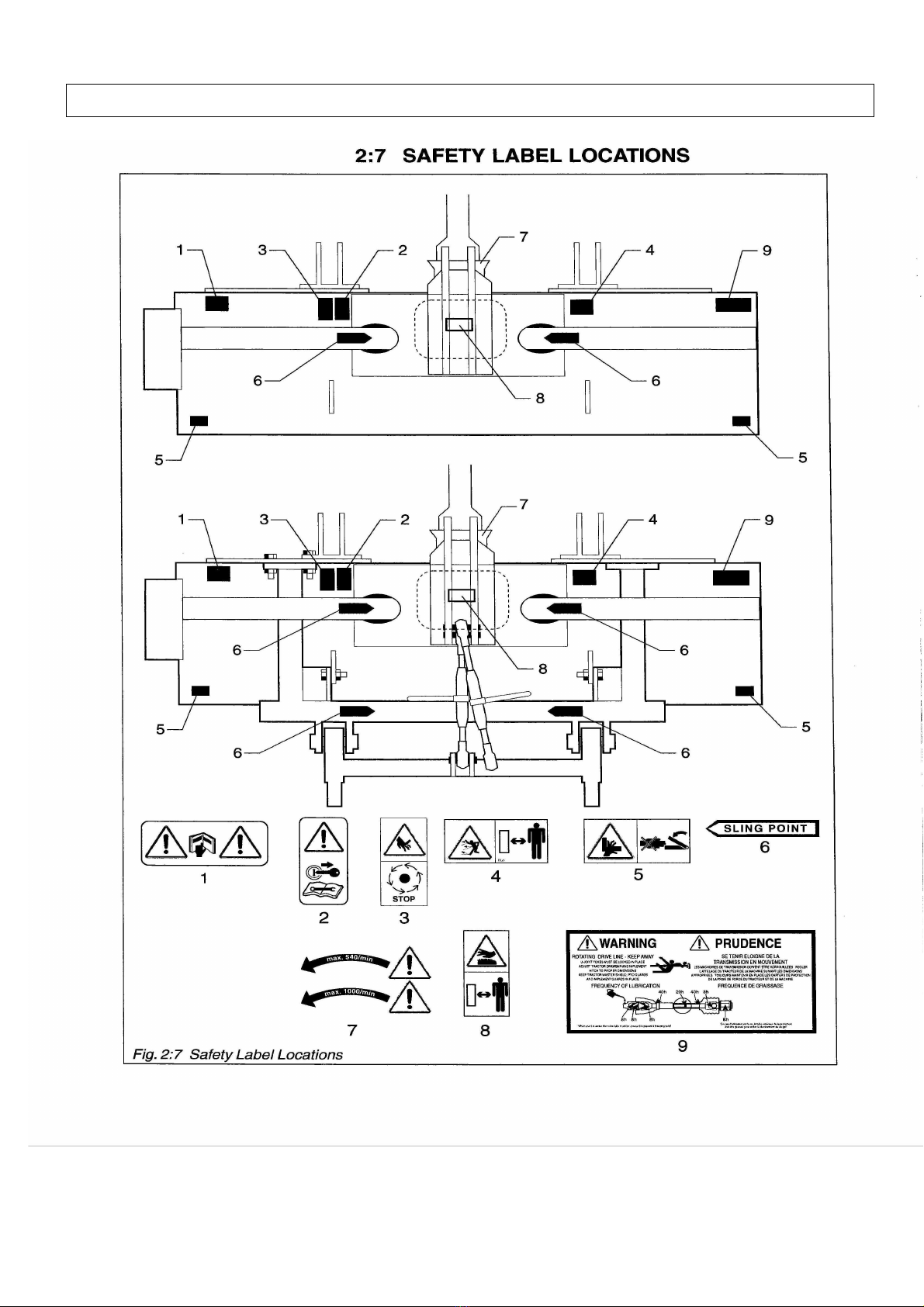
2:7 Safety Label Locations MAINTENANCE
2:8 Safety Labels Explained 6:1 Lubrication
6:2 Preliminary Maintenance
SECTION 3
6:3 Service Schedule
TECHNICAL INFORMATION 6:4 Wear Skids
3:1 Description
6:5 Rotor Blades
3:2 Specifications 6:6 Spike Removal/Fitting
3:3 Dimensions
3:4 Tractor Suitability SECTION 7
3:5 Tractor Tyres SUPPLEMENTS
7:1 Bedformer Kit
7:2 Fitting the Frame

POWAVATOR 150
SECTION 1 INTRODUCTION
1:1 WARRANTY
Should defective material and/or workmanship used in
Manufacture give rise to failure, the products themselves or
The components and sub-assemblies affected, will be
Replaced or repaired free of charge during the first 12 months.
The fitting of non Standen parts, or repairs, or modifications
Carried out by unauthorised persons may invalidate the
Warranty. No major work is to be undertaken without prior
consultation with Standen Engineering Limited.
Save to the extent covered by the warranty, the Company
Shall not be liable in any circumstances for any loss, injury
Or expense, whether direct or indirect, which may arise for any
reason whatsoever from any defect in or otherwise in connection with
any goods supplied or work done by the Company.
1:2 REPLACEMENT PARTS
Use only genuine STANDEN spares, which have the full
Warranty. Refer to the parts section for information on ordering
spares.
1:3 MACHINE LAYOUT
Fig. 1:3 (below) shows the Left, Right, Front and Rear terminology as
used throughout this manual.

POWAVATOR 150
1:4 INTRODUCTION TO THE MANUAL
Standen products comply with the Machinery Directive
89/392/EEC, as amended by Directive 91/368/EEC, 99/44,
99/68.
This manual has been written and provided to enable users
Of the Standen products to :-
1. Understand how the machine operates.
2. Be able to operate the machine safely and without hazard to
either the operator or persons in the vicinity.
3. Be able to use the machine to its full potential.
The operator must read all of the manual and fully understand its
contents before attempting to operate, adjust or service the machine.
The contents of this manual are intended as a guide to the
operation and servicing of the machine. It is not a training
manual.
Whilst all care and attention has been taken in the design and
production of all Standen products, as with all machinery there
remains a certain amount of risk to personnel whilst the machine is in
use.
It is strongly recommended that operators take all possible
precautions to ensure both their own safety and the safety of others
that may be in the vicinity.

POWAVATOR 150
1:5 COPYRIGHTS
Standen Engineering Limited
Hereward Works Station Road,
Ely, Cambridgeshire. CB74BP
This handbook is issued on the condition that it must not be
used, copied or exhibited without their written permission.

POWAVATOR 150
SECTION 2 SAFETY
2:1 NOISE LEVELS
In accordance with the Supply of Machinery (Safety) Regulations
1992 the equivalent continuous A-weighted sound pressure level at
the drivers seat does not exceed 70 dB(A).
2:2 PERSONNEL SAFETY
The STANDEN machine has been designed and constructed to
comply with current Safety Regulations. However, as with all
machinery, there will be inherent dangers whilst operating and
carrying out maintenance on the Implement.
Safety is the responsibility of persons working with the machine.
Think ‘SAFETY’ at all times. Read and remember the contents of this
handbook.
The following list of precautions should be brought to the attention of
all persons operating or working on the machine and should be
complied with at all times.
2:3 SAFETY IN OPERATION
1. Untrained personnel or children must never operate the
Implement.
2. The tractor must be of a suitable size to be able to operate the
Implement safely.
3. Always check that the Implement has been correctly mounted
to the tractor before moving off.
4.
Normal safe working procedures should be adopted at all
times. Reduce speed when moving across sloping ground and
when turning. Do not work on ground where there is a
possibility of overturning or across steep slopes.
5.
Before carrying out any work on the machine, make sure the
Machine is lowered to the ground, switch off the tractor
engine, apply the handbrake and remove the ignition key.

POWAVATOR 150
6. Never work on, or under the machine when it is in a raised
position without suitable blocks/props being used to fully
support the weight of the Implement.
7. The Implement should only be used for the purpose for which
it was designed and as per the instructions in the operators
manual.
8. Wear substantial or proper footwear. Wear gloves when
handling the Implement or parts with sharp edges.
9.
In low light conditions, a sufficient level of artificial light should
be made available to ensure safe working conditions.
2:4 SAFETY IN TRANSIT
1. Only transport the machine at a speed suitable to the
prevailing conditions
2. Be aware of the weight and overall size of the machine at all
times.
3. When travelling on the highway in restricted light or at night, a
suitable lighting board should be attached to the rear of the
machine.

POWAVATOR 150
2:5 SAFETY IN MAINTENANCE
1. Lubricate the Implement as per section 6 of this manual.
2. Check the tightness of all nuts and bolts regularly.
3. Never work on or under the machine when it is in a raised
position without suitable blocks/props being used to fully
support the weight of the Implement.
4. Beware of pinch and trap points. Lock moving parts as
required before working in the vicinity.
5. Wear substantial or proper footwear. Wear gloves when
handling the Implement or parts with sharp edges.
6. Always use mechanical or additional help when lifting heavy
parts.
7.
Use only genuine STANDEN replacement parts.
2:6 SAFETY IN LIFTING
1. Ensure lifting equipment is fully tested and has a rated lifting
capacity capable of lifting the Implement.
2. The machine should only be lifted using nylon straps or
similar. Only fix straps to the main chassis and hitch.
3. Lifting without total care and attention can cause damage to
the machine and may cause injury to personnel.
For weight of machine – refer to 3:2 Technical Specifications
POWAVATOR 150

POWAVATOR 150

POWAVATOR 150
SECTION 3 TECHNICAL INFORMATION
3:1 DESCRIPTION
The Powavator 150 series is ideally suited for either primary or
secondary cultivation’s and will produce seedbeds, control
weeds, incorporate chemicals, trash and sterilising agents.
The implement has an option of Soil Blades or Spikes that are
driven from the tractor PTO. A substantial bevel gearbox with
interchangeable gear sets, enables speed change to suit soil
conditions. An overload clutch unit provides protection to the
machine.
All width versions are suitable for category 2 or 3 mounting in
the central position only. Depth of cultivation is maintained by
side mounted wheels or a rear mounted roller.
3:2 SPECIFICATIONS
Model
70
90
100
120
140
Power
65 – 112kW (90 – 150 HP)
PTO rpm
540 or 1000
TRACTOR
Three point
Linkage
Category 2 or Category 3
MACHINE
WIDTH
Overall
(maximum)
Cultivating
(approx.)
1270mm
(90”)
1780mm
(70”)
2800mm
(110”)
2250mm
(90”)
3050mm
(120”)
2550mm
(100”)
3550mm
(140”)
3050mm
(120”)
4060mm
(160”)
3560mm
(140”)
WEIGHT
Standard
Spec. Kg
850Kg
1100Kg
1200Kg
1450Kg
1700Kg
Cultivating
Depth
Up to 200mm (8”)
Control
Device
Side mounted wheels or Rear mounted Roller
190,215,235 and 260 rpm with standard Gears Supplied
ROTOR
Speed
(approx.)
173 and 290 rpm with ‘optional’ gears

POWAVATOR 150
3:3 DIMENSIONS
See table 3:2
3:4 TRACTOR SUITABILITY
Power requirement – up to 112kW – 150 HP
The tractor must be of a suitable size to suit land conditions
and to handle and lift the implement safely.
3:5 TRACTOR TYRES
Ensure that all tractor tyres are at the manufacturers
recommended pressures and that left and right hand side
tyres are identical and state of wear is approximately the
same.

POWAVATOR 150
SECTION 4 SETTING INSTRUCTIONS
4:1 ATTACHING THE POWAVATOR TO THE
TRACTOR
The Powavator 150 Series is suitable for either category 2 or 3
three point linkage, it must be mounted in the central position
only. (See fig.4:1a)
Fig. 4:1a Lower Mounting Brackets
To determine the correct mounting position :-
1. With the Powavator on a firm level surface, adjust the
depth control device until the machine gearbox input shaft
is horizontal.
2. Reverse the tractor up to the machine to give 150mm
(6 ins) minimum engagement of the male half of the PTO
drive shaft in the female tube when connected to the
tractor. The safe working length between centres of the
cross journals is 660-870mm (26-34 inches).
3. Position the tractor lower link ball ends in line with the
machine lower mounting brackets.

POWAVATOR 150
4. APPLY THE TRACTOR HANDBRAKE AND SWITCH
OFF THE ENGINE
5. Insert the mounting pins through the brackets and the
tractors lower link ball ends. Secure using clip pins.
6. Adjust the tractor top link length and fit to the machine
using the mounting pin supplied. Secure using a clip pin.
7. Fit and adjust stabiliser bars or chains to limit sway to a
maximum of 50mm (2 inches).
8. Fit the PTO drive shaft to the tractor PTO, ensuring that
the end yoke quick-release pin locates fully in the tractor
PTO shaft groove. Clip the safety check chain to the
tractor.
9. Before engaging the tractor PTO, check that the length of
the PTO drive shaft is within the specified operating range
when the machine is in the horizontal and raised positions.
When raised, the angle on the universal joint must not
exceed 40º or damage may occur (see fig 4:1b).
10.Raise the parking prop and secure in the raised position.
Fig. 4:1b

POWAVATOR 150
4:2 REMOVING THE POWAVATOR FROM THE
TRACTOR
1. Locate and secure the parking prop in the lowered
position. Lower the Powavator to the ground.
2. APPLY THE TRACTOR HANDBRAKE AND SWITCH
OFF THE ENGINE.
3. Disconnect the PTO drive shaft safety guard check
chain from the tractor
4. Depress the quick-release pin on the tractor end yoke
and slide the yoke off the tractor PTO shaft and put it in
the stow position.
5. Disconnect the tractor top link from the machine.
6. Remove the stabiliser bars or chains and then
disconnect the tractor lower links from the machine.

POWAVATOR 150
POWAVATOR 150
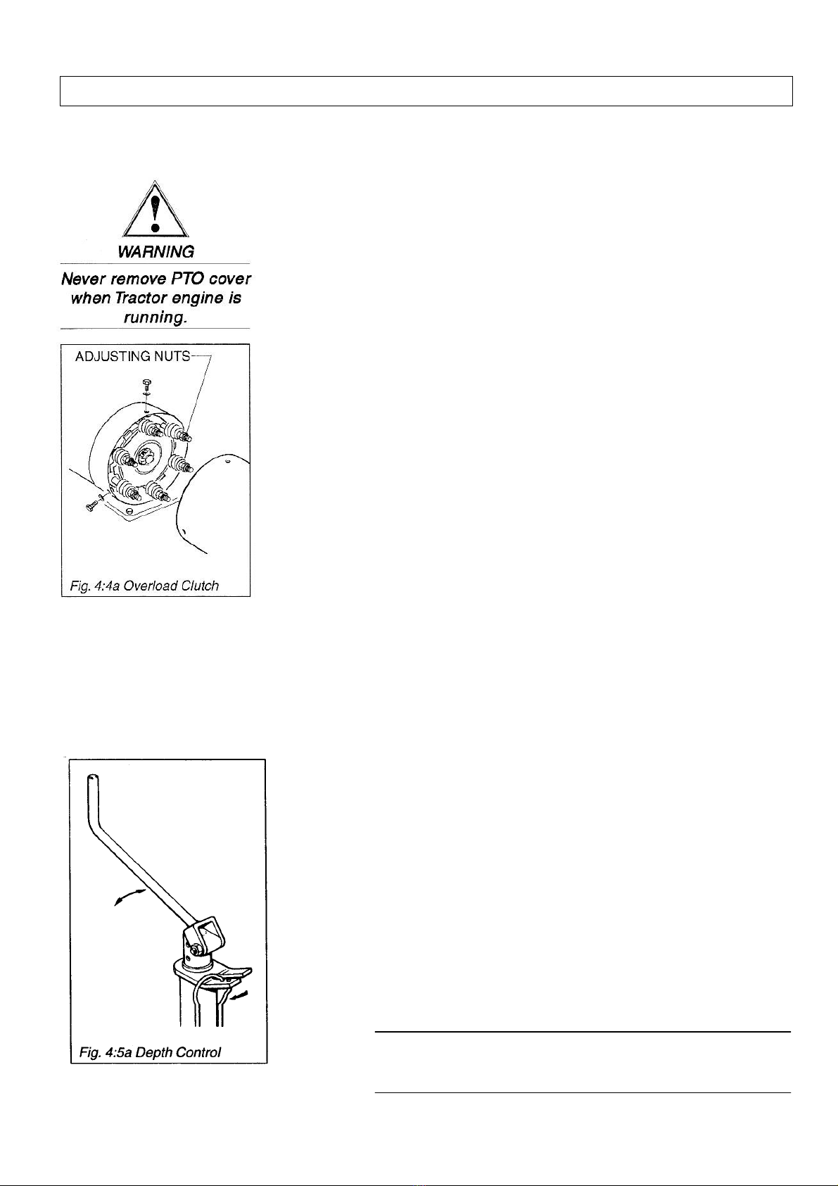
4:4 OVERLOAD CLUTCH UNIT
The overload clutch unit (part of PTO shaft supplied) protects the
machine transmission should the blades encounter an obstruction.
CAM CLUTCH UNIT (machines prior to 2010)
The cam clutch unit is supplier-set and is not adjustable. For any
other information refer to the suppliers literature (supplied with the
machine).
FRICTION CLUTCH UNIT (machines from 2010)
If set too loosely the blades will turn erratically leading to excessive
friction plate wear and poor work finish. If set too tightly it will not
provide the necessary protection.
To adjust the clutch setting:
1. Disengage the PTO drive and switch off the tractor engine.
2. Disconnect the PTO drive shaft safety guard check chain and
remove the clutch guard from the machine.
3. Tighten two opposite nuts until the springs are coil bound as
this will help to centralise the plates.
4. Tighten the other nuts until they just touch the washers , then
tighten each nut an additional 2 1/2 complete turns for 540
rpm, or 1 3/4 turns for 1000 rpm.
5. Slacken off the two coil bound springs and reset the same as
the others.
6. Refit and secure the clutch unit safety gurad and clip the PTO
drive shaft safety guard check chain to the machine.
4:5 DEPTH CONTROL
The depth of cultivation is controlled down to a maximum
of 200mm (8 inches) by means of side mounted wheels
or a rear mounted roller.
To adjust depth :-
1. Unclip the screw adjuster handles and rotate
clockwise to increase depth or anticlockwise to
decrease depth.
2. When correct, fold the handles down and secure
using the clip.
NOTE
Adjustment should be the same on both sides to ensure
even depth of cultivation
Table of contents
Other Standen Farm Equipment manuals

Standen
Standen SP Series User manual

Standen
Standen T2 Service manual

Standen
Standen ZENO Series User manual

Standen
Standen T2 User manual

Standen
Standen POWAVATOR 400 Service manual

Standen
Standen BX Series User manual

Standen
Standen T2 Service manual

Standen
Standen SP Series User manual

Standen
Standen SP Series User manual

Standen
Standen SP Series User manual


Popular Farm Equipment manuals by other brands

Schaffert
Schaffert Rebounder Mounting instructions

Stocks AG
Stocks AG Fan Jet Pro Plus 65 Original Operating Manual and parts list

Cumberland
Cumberland Integra Feed-Link Installation and operation manual

BROWN
BROWN BDHP-1250 Owner's/operator's manual

Molon
Molon BCS operating instructions

Vaderstad
Vaderstad Rapid Series instructions


