Stanley MA900ñ Installation instructions

Access Technologies Technical News September 8, 2005
If you have any questions concerning this procedure, contact
Access Technologies Technical Support, at 1-800-422-6489 Option 3.
Cover Page Tech Tip: TT050908
TECH TIP
MA900 Manual Revision C
Prepared by: Jeff Bonas Engineer: Dean Negrelli Tech Tip: TT050908
PCN: 05-50 RDW: ________ Reference Tech Tip: ________
Engineering Document Number: ________
Summary Information
Product Information
Bifold Swing Accessories Operators / Drives Sensors
Slide Class 2 Controls Panels / Hardware
Tech Tip Classification
Adjustment Customer Complaints FAQs Retrofit/Upgrade Instructions
Installation Clarifications Service Design Change Description
Release Action
Level 1 - Does not impact maintenance or operation of door. (Only Safety/Liability and Engineering need to sign.)
Level 2 - Full sign off required.
Release Information (initial and date)
Safety/Liability _________________________
Engineering _________________________
Technical Support _________________________
Field Operations _________________________
Quality _________________________

Access Technologies Technical News September 8, 2005
If you have any questions concerning this procedure, contact
Access Technologies Technical Support, at 1-800-422-6489 Option 3.
Page 1 of 1 Tech Tip: TT050908
TECH TIP
MA900 Manual Revision C
Prepared by: Jeff Bonas Engineer: Dean Negrelli Tech Tip: TT050908
Action Required
Replacement Required None, Information Only Inspection Required Where Symptom Exists New Installation Only
Inspect During Maintenance
Attached is the latest version of the MA900, Installation and Owner’s Manual, 203936,
Rev. C.
This manual has been revised to include the MS Sedco TDM Time Delay Module. The changes
can be found at the following places:
Page 16, Figures 21 and 22.
Page 17, Figure 23 and Notes.
Page 22, Optional Sequencing Timers.
Also attached are the MS Sedco TDM Installation Instructions. You should find a copy of
this manual inside the header of the MA900.

MA900
Installation and Owner’s Manual
203936 Rev. C

© 2005, The STANLEY WORKS. ALL RIGHTS RESERVED.
203936 Rev. C
MA900 Installation Manual
2

© 2005, The STANLEY WORKS. ALL RIGHTS RESERVED.
203936 Rev. C
MA900 Installation Manual
3
Table of Contents
Safety Requirements . . . . . . . . . . . . . . . . . . . . . . . . . . . . . . . . . . . . . . . . . . . . . . . . . . . . . . . . . . . . . . . . . 4
Introduction . . . . . . . . . . . . . . . . . . . . . . . . . . . . . . . . . . . . . . . . . . . . . . . . . . . . . . . . . . . . . . . . . . . . . . . . . . 5
Definitions of Terms . . . . . . . . . . . . . . . . . . . . . . . . . . . . . . . . . . . . . . . . . . . . . . . . . . . . . . . . . . . . . . . . . . . . . . . 6
Stanley MA900 Features and Functions . . . . . . . . . . . . . . . . . . . . . . . . . . . . . . . . . . . . . . . . . . . . . . . . . . . . . . . 6
Minimum Installation Requirements . . . . . . . . . . . . . . . . . . . . . . . . . . . . . . . . . . . . . . . . . . . . . . . . . . . . . . . . . . 7
Items Supplied . . . . . . . . . . . . . . . . . . . . . . . . . . . . . . . . . . . . . . . . . . . . . . . . . . . . . . . . . . . . . . . . . . . . . . . . . . . . 8
Tools Required . . . . . . . . . . . . . . . . . . . . . . . . . . . . . . . . . . . . . . . . . . . . . . . . . . . . . . . . . . . . . . . . . . . . . . . . . . . . 9
Installation Procedures . . . . . . . . . . . . . . . . . . . . . . . . . . . . . . . . . . . . . . . . . . . . . . . . . . . . . . . . . . . . . . 10
Header Assembly Installation . . . . . . . . . . . . . . . . . . . . . . . . . . . . . . . . . . . . . . . . . . . . . . . . . . . . . . . . . . . . . . . . . . 10
Connect Actuation Devices . . . . . . . . . . . . . . . . . . . . . . . . . . . . . . . . . . . . . . . . . . . . . . . . . . . . . . . . . . . . . . . . . . . . 15
Power Requirements . . . . . . . . . . . . . . . . . . . . . . . . . . . . . . . . . . . . . . . . . . . . . . . . . . . . . . . . . . . . . . . . . . . . . . . . . 15
Wiring Diagrams . . . . . . . . . . . . . . . . . . . . . . . . . . . . . . . . . . . . . . . . . . . . . . . . . . . . . . . . . . . . . . . . . . . . . . . . . . . . . 16
Tune-In Procedures . . . . . . . . . . . . . . . . . . . . . . . . . . . . . . . . . . . . . . . . . . . . . . . . . . . . . . . . . . . . . . . . . . . . . . . . . . 18
Optional Sequencing Timers . . . . . . . . . . . . . . . . . . . . . . . . . . . . . . . . . . . . . . . . . . . . . . . . . . . . . . . . . . . . . . . . . . . . . .22
Safety Checks . . . . . . . . . . . . . . . . . . . . . . . . . . . . . . . . . . . . . . . . . . . . . . . . . . . . . . . . . . . . . . . . . . . . . . . . . . . . . . . 23
Safety Decals . . . . . . . . . . . . . . . . . . . . . . . . . . . . . . . . . . . . . . . . . . . . . . . . . . . . . . . . . . . . . . . . . . . . . . . . . . . . . . . . 23
Troubleshooting . . . . . . . . . . . . . . . . . . . . . . . . . . . . . . . . . . . . . . . . . . . . . . . . . . . . . . . . . . . . . . . . . . . . . . . . . . . . . . . . .25
Warranty
The MA900 Series is warranted against defects in material and workmanship for a period of one year
from date of installation.

© 2005, The STANLEY WORKS. ALL RIGHTS RESERVED.
203936 Rev. C
MA900 Installation Manual
4
Safety Requirements
Please read this section carefully. It contains important information concerning the operating features of your Stanley MA900 Door
Operator, as well as safety precautions to be taken before, during and after installation.
This caution symbol appears throughout the manual. It identifies important safety instructions. Read these
instructions carefully. Failure to follow these instructions may result in serious or fatal personal injury or
property damage.
Information symbol identifies notes that provide important information about the installation and
operation of the MA900.
Do not wear rings, watches or loose clothing while
installing or servicing the door operator.
Daily safety checks must be made to assure pro-
per door operation. See Safety Checks section of
this manual or the decal on the side of the operator
header.
ANSI Standard A156.19 requires that specific labels
be applied to the door. See Safety Decals section of
this manual for information on applying these labels.
To reduce the risk of electrical shock, connect the
power wire to only a properly grounded outlet.
Never let children operate or play near the door.
Keep RF transmitters in a location inaccessible to
children. Misuse of a door-actuation device may
result in serious injury.
Operate the door only when it is fully visible and
clear of any obstruction. Keep the door in sight until
it is completely closed. KEEP CHILDREN
AND PETS AWAY FROM THE DOOR WHILE IT
IS MOVING.
If damage to any mechanical drive or structural com-
ponent of the unit is observed, discontinue use and
contact an authorized Stanley dealer or the Stanley
Customer Service Department.
If permanent wiring is required by local code, discon-
nect power at the fuse box or circuit breaker box
before attempting wiring connections.
Check local building and electrical codes for manda-
tory installation and wiring requirements.
Read carefully the assembly and mounting sections
of this manual. They provide information about the
tools, and in some cases the additional hardware,
required to ensure a safe and speedy installation.
★
★
★
★

© 2005, The STANLEY WORKS. ALL RIGHTS RESERVED.
203936 Rev. C
MA900 Installation Manual
5
Fig. 4
Left–hand inswing door.
(for LH and RHR door opening)
3X3765
Fig. 2
Right–hand inswing door.
(for RH and LHR door opening)
3X3755
Fig. 3
Left–hand outswing door.
(for LH and RHR door opening)
3X3760
Fig. 1
Right–hand outswing door.
(for RH and LHR door opening)
3X3750
Introduction
This Installation manual provides you with the information you need to install the Stanley MA900 Door Operator. The Stanley MA900
Installation Kit contains hardware, components and materials required for a typical installation. Make sure the operator you have select-
ed meets your application requirements. The Stanley MA900 is available in four configurations (see Figs. 1-4):
The electrical connection of the Stanley MA900 to the building wiring
must be done by a qualified electrician.
Fig. 3
Left–hand outswing door.
(for LH and RHR door opening)
3X3760
X= 1 for clear anodized, 2 for dark bronze anodized.

© 2005, The STANLEY WORKS. ALL RIGHTS RESERVED.
203936 Rev. C
MA900 Installation Manual
6
Definitions of Terms
door jamb – Either of the two vertical sides of a doorway.
electric strike – Electronically controlled latching/
unlatching device.
fail safe lock – An electric lock that automatically unlocks
with any power interruption.
fail secure lock – An electric lock that requires power
to unlock.
header – The enclosure that contains the operator.
operator – The mechanism that drives the door.
push plate – A wall-mounted actuator switch. When the
plate is pushed, a signal is sent to the operator.
reveal – The distance from the mounting surface of the
operator to the face of the door.
stack pressure – A force on the door, created by an internal
air handling system or external environmental conditions.
strike plate – The metal plate on the door jamb that holds the
bolt of the lock when the door is closed.
Stanley MA900 Features and Functions
Magic-Touch™ A feature that allows the door to be actuated by
a slight movement of the door.
Manual Operation If power is shut off, the door functions as a
manual door.
Lock Delay Delays the operation of the door 1/2 sec to allow a
lock to release.
Power Close In a building in which stack pressure exerts a force
that prevents the door from closing, the Power Close feature can
be actuated to help it to close.
Swing-Safe Technology The electronic safety control senses an
obstruction during the opening cycle of the door. The operator
immediately reverses the door direction, allowing time for the
obstruction or person to clear the swing path area of the door.
Adjustable Time Delay When it reaches the fully open position,
the door pauses for a specified time before closing. The time delay
is adjustable, and must be set to at least 5 seconds. The maximum
available adjustment is about 30 seconds.
Adjustable Opening Angle The angle of the door at the fully open
position can be set in the range of 90˚ to 120˚.
On/Off Switch When the switch is in the On position, power is
supplied to the operator. When the switch is in the Off position, the
MA900 works as a manual closer.
Mode Switch Controls Hold Open or Operating Mode
(Day or Night).
• Hold Open - When activated the door is moved and held
in the fully open position.
• Day and Night Operating Modes - In Day mode all features
are fully operational. In Night mode actuators (for example,
a push plate or an RF transmitter) are deactivated. If the
Magic-Touch™ feature has been turned on, it remains
active.
Sequential Operation This feature provides for sequenced oper-
ation of two units. For example, in a vestibule the opening of the
second unit can be delayed 1 to 30 sec after the opening of the first.
Easy Interface The MA900 can be easily interfaced with various
access control system components, including keypads, card
access, proximity, electric strikes and exit devices with electric
latch retraction.

© 2005, The STANLEY WORKS. ALL RIGHTS RESERVED.
203936 Rev. C
MA900 Installation Manual
7
Minimum Installation Requirements
To be suitable for the installation of a Stanley MA900, the door and frame must meet the
following minimum requirements:
Check with the building manager or other responsible individual to make
sure that you are working on the correct door.
1. The MA900 must be mounted on the interior side of the building.
2. The door can weigh no more than 250 lb.
3. The door can be no more than 44 in. wide.
4. If there is a manual closer, it must be removed or made inoperable.
5. The door must be in good working order. The hinges must work properly; the door must swing freely
through its entire range.
6. The frame must be made of 16 gauge welded steel or better; or the mounting surface must be masonry; or
additional support must be provided behind the operator (see Figs 5 and 6).
7. For an outswing door, the reveal must be in the range 0-6 in. For an inswing door the reveal must be 0 in.
8. Power for the MA900 should be installed before starting the installation of the operator.
See Electrical Specifications section of this manual.
★
Fig. 5
Typical left hand outswing application
Fig. 6
Typical right hand inswing application

© 2005, The STANLEY WORKS. ALL RIGHTS RESERVED.
203936 Rev. C
MA900 Installation Manual
8
Items Supplied
Operator Components
The Stanley MA900 operator kit contains the following items (see Fig. 7).
Fig. 7
MA900 Operator Kit Contents

© 2005, The STANLEY WORKS. ALL RIGHTS RESERVED.
203936 Rev. C
MA900 Installation Manual
9
Hardware
The installation and mounting hardware kit contains the
following items:
Tools Required
You will need the following tools to install the Stanley MA900:
Riv-nut tool for 1/4-20 Riv-nut and instructions
Digital stopwatch
Force gauge
Number 2 Phillips screwdriver
Small flat-blade screwdriver
3/32” and 3/8” Allen wrenches
Center punch
Hammer
Tape measure
Diagonal cutters (wire strippers)
Step ladder
Electric drill
1/8” drill bit
25/64” drill bit
3/8” drill bit
Tape (for example, electrical tape) to hold template on
door frame
1/2” box-end wrench
5/8” box-end wrench (or adjustable wrench)
Carbide drill bits if the operator is being attached to a
masonry surface.
ALL LABELS
REQUIRED BY
ANSI A156.19

© 2005, The STANLEY WORKS. ALL RIGHTS RESERVED.
203936 Rev. C
MA900 Installation Manual
10
Installation Procedures
Header Assembly Installation
Outswing Door – Mounting Preparation
Fig. 8
Template alignment, outswing door
1. Select the right hand or left hand side of the installation
template.
2. Position the template (see Fig. 8).
• Separate the top of the template (for the header) from the
bottom (for the door arm) along the perforation.
• Align the bottom of the header template with the bottom
edge of the door frame.
• Align the indicated vertical line on the template with the
center line of the hinge.
• Use tape to hold the template in position.
3. Verify that the template is aligned properly; reposition
if necessary.
4. Use a center punch to make a small depression on the frame
at the center of each of the six hole locations marked “A” on
the template.
5. If additional support backing is used, use a center punch to
make a small depression at the center of each of the three
hole locations marked “B” on the template.
6. If the electrical wire is to be run through the back of the
header, use a center punch to make a small depression on
the frame at the center of the hole location marked “C” on
the template.
7. Remove the template.
8. Use a 1/8” bit to drill a pilot hole at each hole location; then
use a 25/64” bit to drill each hole marked “A” out to the size of
the Riv-nut.
9. Thread a Riv-nut fully onto the Riv-nut tool (see Fig. 9).
(The Riv-nut tool is not supplied.)
10. Insert the Riv-nut into a mounting hole in frame.
Fig. 9
Installation of Riv-nuts
11. Use a 3/8” Allen wrench and a 5/8” open-end wrench (or small
adjustable wrench) as shown in Fig. 9. Hold the Allen wrench
and turn the Riv-nut tool counterclockwise (ccw) until the
Riv-nut is installed and tightened. Do not over-tighten; this will
cause excessive deformation.
12. Remove the Riv-nut tool.
13. Install the remaining five Riv-Nuts in the holes on the frame.
14. Install 1/4-20 x 1” pan-head screws into the lower left and
lower right Riv-nuts, and tighten about halfway.
15. If additional support backing is used, drill out the three hole
locations marked “B” on the template to the desired size
(hardware not provided).
16. If the electrical wire is to be run through the back of the
header, drill the hole location marked “C” on the template to
the desired size for wire.
The hole for the wire must be free of burrs and
rough edges.

© 2005, The STANLEY WORKS. ALL RIGHTS RESERVED.
203936 Rev. C
MA900 Installation Manual
11
Inswing Door – Mounting Preparation
Fig. 10
Template alignment, inswing door
1. Make sure that proper additional support is installed as
shown in Fig. 6.
2. Select the right hand or left hand side of the installation
template.
3. Position the template (see Fig. 10).
• Align the indicated horizontal line on the template with
the top edge of the door frame.
• Align the indicated vertical line on the template with the
centerline of the hinge.
• Use tape to hold the template in position.
4. Verify that the template is aligned properly; reposition
if necessary.
5. Use a center punch to make a small depression at the center
of each of the hole locations marked “A,” “B,” and “D” on
the template.
6. If electrical wire is to be run through the back of the header,
use a center punch to make a small depression at the center
of the hole location marked “C” on the template.
7. Remove the template.
8. Use a 1/8” bit to drill a pilot hole at each of the two hole
locations marked “D” on the template.
9. Drill the header mounting holes marked “A” and “B” to the
desired size for mounting hardware (not supplied).
10. Install two mounting screws into lower left and lower right
hand mounting holes and tighten about halfway.
11. If electrical wire is to be run through the back of the header
drill the hole location marked “C” on the template to the
desired size for wire.
The hole for the wire must be free of burrs and
rough edges.
Install Header Assembly
1. Install the header assembly over the two screws, then slide it
sideways so that the screw occupies the smaller part of the
opening (see Fig. 11).
Fig. 11
Header mounting
2. Tighten the two screws so that they are snug but not fully tight.
3. Install the remaining four screws and 1/4” lock washers so
that they are snug but not fully tight.
4. Fully tighten all mounting screws.

Connect to 117 VAC Power Supply
The electrical connection must be made by a
qualified electrician. See Electrical
Specifications page 15, for requirements.
1. Depending on the application, run the electrical wire through
either the hole in top of the header (wall outlet), or the hole in
the back of the header (concealed).
Make sure that the wire access hole on the
operator is free of burrs and rough edges.
2. Seal the unused hole with the plug provided.
3. Connect the wires to the leads on the power harness
(see Fig. 12).
Fig. 12
Wiring harness
Install Door Arm Assembly - Outswing Door
Do not wear rings, watches or loose clothing
while installing or servicing the door operator.
Fig. 13
Outswing door arm assembly
In most cases the door should open to a minimum of 90˚. The door
arm is attached to the door by means of a door shoe (see Fig. 13).
The location of the door shoe varies depending on the depth of the
reveal. Use the template provided to position the door shoe.
1. Set the power switch on the side of the header to the “ON”
position (power up).
2. Set the mode switch to Hold Open. The operator shaft rotates
to its mechanical stop (fully open) and stays there. Verify that
the dowel pin on the operator shaft is against the stop
(see Fig. 14).
Fig. 14
Full-stop position
If the operator shaft does not come to a full stop
with the dowel pin against the stop, decrease the
back check time, as described in step 2 of Door
Opening Adjustments section of this manual.
Increase the stall force as described in step 3 of
Door Opening Adjustments section of this manual.
3. Select the right hand or left hand side of the door arm
installation template.
4. Position the template:
• Align the top of the template with the top edge of
the door.
• Align the indicated vertical line on the template with the
center line of the hinge.
5. Measure the depth of the reveal.
6. Identify and mark the pair of hole locations that corre-
sponds to the reveal depth on the template.
7. Use tape to attach the template to the door.
8. Verify that the template is aligned properly; reposition
if necessary.
9. Use a center punch to make a small depression in the door at
the center of each of the two hole locations on the template.
© 2005, The STANLEY WORKS. ALL RIGHTS RESERVED.
203936 Rev. C
MA900 Installation Manual
12
★

© 2005, The STANLEY WORKS. ALL RIGHTS RESERVED.
203936 Rev. C
MA900 Installation Manual
13
10. Remove the template.
11. If the door is made of metal, use a 25/64” bit to drill holes for
the Riv-nuts supplied, or a 3/8” bit to drill holes for the 1-5/8”
sex nuts supplied.
12. If the door is made of wood, use a 3/8” bit to drill holes for the
1-5/8” sex nuts supplied.
13. Attach the door shoe to the door using the two 1/4-20 x 1”
flat-head screws supplied.
14. Thread the rod into the door shoe.
15. Open the door to the desired fully open position.
16. Slide the door arm onto the operator shaft.
Fig. 15
Attachment of arm to operator shaft
17. Install the operator arm retainer washer and screw to the
bottom of the operator shaft (see Fig. 15).
18. Use a 1/2” box end wrench to tighten the bolt that attaches the
door arm to the operator shaft.
Make certain this bolt is fully tight.
19. Set the power switch on the side of the header to the “Off”
position (power down).
20. Test door operation by manually pushing the door to its fully
open position.
• If the door opens to the desired angle, go to Tune-In
Procedures section of this manual.
• If the door does not open to the desired angle, loosen the
bolt on the operator output arm. Power up, set the mode
switch to Hold Open, and repeat the procedure from
step 15.
Install Door Arm Assembly - Inswing Door
Do not wear rings, watches or loose clothing
while installing or servicing the door operator.
Fig. 16
Inswing door arm assembly
See Fig. 16. In most cases the door should open to a minimum of
90˚. The door arm terminates in a block, which travels in a track
that is secured to the door by two brackets.
1. Power up.
2. Set the mode switch to Hold Open. The operator shaft rotates
to its mechanical stop (fully open) and stays there. Verify that
the dowel pin on the operator shaft is against the stop
(see Fig. 17).
Fig. 17
Full stop position
If the operator shaft does not come to a full stop with
the dowel pin against the stop, decrease the back
check time, as described in step 2 of Door Opening
Adjustments section of this manual. Increase the
stall force as described in step 3 of Door Opening
Adjustments section of this manual.
★
★

© 2005, The STANLEY WORKS. ALL RIGHTS RESERVED.
203936 Rev. C
MA900 Installation Manual
14
3. Identify the two 1/8” holes made previously on the door for
mounting the track brackets.
4. If the door is made of metal, use a 25/64” bit to drill holes for
the Riv-nuts supplied, or a 3/8” bit to drill holes for the sex nuts
supplied.
5. If the door is made of wood, use a 3/8” bit to drill holes for the
sex nuts supplied.
6. Attach the two track brackets, using the 1/4-20 x 1” flat-head
screws supplied.
7. Assemble the slide block into the door track.
8. Assemble the Allen screws into the slide block so that the
block slides smoothly and has no side-to-side movement.
9. Slide one end of the track onto the track bracket as shown
in Fig. 18.
Fig. 18
Sliding one end of track onto track bracket
Fig. 19
Pressing other end of track onto track bracket
10. Press the other end of the track onto the track bracket as
shown in Fig. 19 and assemble using the two
1/4-20 x 9/16” flat-head screws supplied.
11. Tighten the screws fully.
12. Assemble the pin into the door arm.
13. Assemble the door arm and pin assembly into the slide block in
the door track.
14. Assemble the door arm onto the operator output shaft. Do not
tighten the hex bolt.
15. Assemble the operator arm retainer using the 1/4-20 x 9/16”
flat-head screw supplied.
16. Open the door to the desired position.
17. Tighten the bolt on the door arm.
18. Set the mode switch to the Day position.
19. Power down.
20. Test door operation by manually pushing the door to its fully
open position.
• If the door opens to the desired angle, go to Tune-In
Procedures section of this manual.
• If the door does not open to the desired angle, loosen the
bolt on the operator output arm. Power up, set the mode
switch to Hold Open, and repeat the procedure from
step 16.

© 2005, The STANLEY WORKS. ALL RIGHTS RESERVED.
203936 Rev. C
MA900 Installation Manual
15
Connect Actuation Devices
See the electrical specifications below for specific wiring
requirements.
Electrical Specifications
The MA900 can be wired to accommodate several applications
requirements. Figures 21 through 25 show how to wire the
MA900 for each specific application.
Shut off power at a circuit breaker, or unplug the
operator, before making any changes to wiring.
Power Requirements
See Fig. 20 for proper location of concealed wiring.
117 VAC, 15 Amp service for one or two operators.
Dedicated 20 Amp service for three or four operators.
If an electrical cord is used to power the operator, it
must be UL Listed.
The electrical outlet and wire should be mounted
out of reach. Recommendation: at least 7 feet
above the floor.
Fig. 20
Position of wire access hole for concealed wiring

Wiring Diagrams
© 2005, The STANLEY WORKS. ALL RIGHTS RESERVED.
203936 Rev. C
MA900 Installation Manual
16
Fig. 22
Wiring diagram for single door with electric lock
Fig. 21
Wiring diagram for single door without lock (factory wiring)

© 2005, The STANLEY WORKS. ALL RIGHTS RESERVED.
203936 Rev. C
MA900 Installation Manual
17
Fig. 24-25
Reserved for future use
Notes:
1.) Electric locks and radio receivers: Additional power supply required for electric locks and radio receivers.
2.) Insulating spare wires: Insulate all unused wires from one another.
3.) Activation devices in vestibule: If push buttons or other activating devices are needed between doors in a
cccccvestibule they must be connected to the timing and sequencing module per the instructions provided with the module.
4.) Momentary electric strikes: If using an electric strike that requires only a momentary contact to prevent overheating,
ccccca one-shot relay may be needed. Upon receiving an activating signal, this type of relay provides an open or closed
ccccccontact for an adjustable time interval. An example is Magnecraft part number TDRSRXP-24V.
Fig. 23
Wiring diagram for vestibule function

© 2005, The STANLEY WORKS. ALL RIGHTS RESERVED.
203936 Rev. C
MA900 Installation Manual
18
Tune-In Procedures
Tuning-in is the process of adjusting the operating characteristics
of the Stanley MA900 — opening time, closing time, etc.
The door must operate in accordance with the ANSI
(American National Standards Institute) Standard for
Power Assist and Low Energy Power Operated Doors,
A156.19.
The tune-in procedures must be followed completely,
and in the order presented here, to make certain that
the door is in full compliance with the ANSI standard.
Check your local code requirements to assure com-
pliance in your area.
Cam Adjustments
Fig. 26
Overall view of operator assembly, with callouts to cams
Back-Check Cam
The door opens at normal speed until it is almost fully open; then
back check is activated, and the door moves slowly to the fully
open position. The ANSI standard specifies that the back check
must not occur before the door is open at least 60˚. Normally the
back check occurs about 20˚ before the door reaches the fully
open position.
1. Power up. Test door operation by setting the mode switch to
Hold Open, or by using the external actuation device. Make
sure that back check occurs after the door is open at least
60˚, and at least 10˚ before the door is fully open. If it is in
compliance with the ANSI standard, go to Latch-Check Cam,
below. If it is not in compliance with the ANSI standard, go to
step 2.
2. Power down.
3. Using a 3/32” Allen wrench, loosen the set screw on the back-
check cam (top cam) (see Fig. 26).
4. Use the Allen wrench to rotate the back-check cam.
5. On a right-outswing or left-inswing door, rotate the cam count-
er clockwise (ccw) to increase, clockwise (cw) to decrease,
the back-check angle.
6. On a left-outswing or right-inswing door, rotate the cam cw to
increase, ccw to decrease, the back-check angle.
7. Use the 3/32” Allen wrench to tighten the Allen screw.
8. Power up.
9. Test door operation by setting the mode switch to Hold Open,
or by using an external actuation device. If necessary, power
down and readjust the cam.
Latch-Check Cam
The door closes at normal speed until it is almost fully closed; then
latch check is activated and the door moves slowly to the fully
closed position. The ANSI standard specifies that the latch check
must occur 10˚ before the door reaches the fully closed position.
1. Power down. Test door operation by moving the door to the
open position and releasing the door. Make sure that the latch
check occurs 10˚ before the door is fully closed. If it is in com-
pliance with the ANSI standard, go to Adjust Opening and
Closing Times, below. If it is not in compliance with the ANSI
standard, go to step 2.
2. Power down.
3. Using a 3/32” Allen wrench, loosen the set screw on the latch-
check cam (bottom cam) (see Fig. 26).
4. Use the Allen wrench to rotate the latch-check cam.
• On a outswing or inswing door, rotate the cam ccw to
increase, cw to decrease, the latch-check angle.
• On a left-outswing or right-inswing door, rotate the cam
clockwise to increase, counter clockwise to decrease the
latch-check angle.
5. Use the 3/32” Allen wrench to tighten the Allen screw.
6. Power up.
7. Test door operation by manually pushing the door open and
checking the position at which latch check occurs. If neces-
sary, power down and readjust the cam.
Do not wear rings, watches or loose clothing
while installing or servicing the door operator.
Table of contents
Other Stanley Door Opening System manuals
Stanley
Stanley QDC-200 User manual
Stanley
Stanley QED300 User manual
Stanley
Stanley QSRK5267 User manual
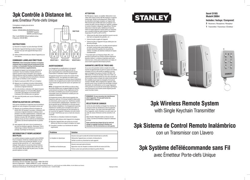
Stanley
Stanley 28064 User manual

Stanley
Stanley Dura-Glide Series User manual

Stanley
Stanley Dura-Glide Series Installation guide
Stanley
Stanley Dura-Glide 2000AG Series User manual
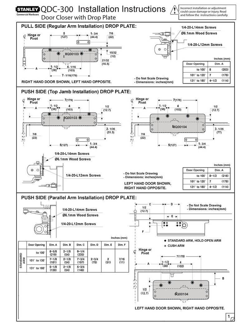
Stanley
Stanley QDC-300 User manual

Stanley
Stanley QED300 User manual

Stanley
Stanley M-Force User manual
