manuals.online logo
Brands
  1. Home
  2. •
  3. Brands
  4. •
  5. Stanley
  6. •
  7. Door Opening System
  8. •
  9. Stanley QSRK5267 User manual

Stanley QSRK5267 User manual

This manual suits for next models

1

Other Stanley Door Opening System manuals
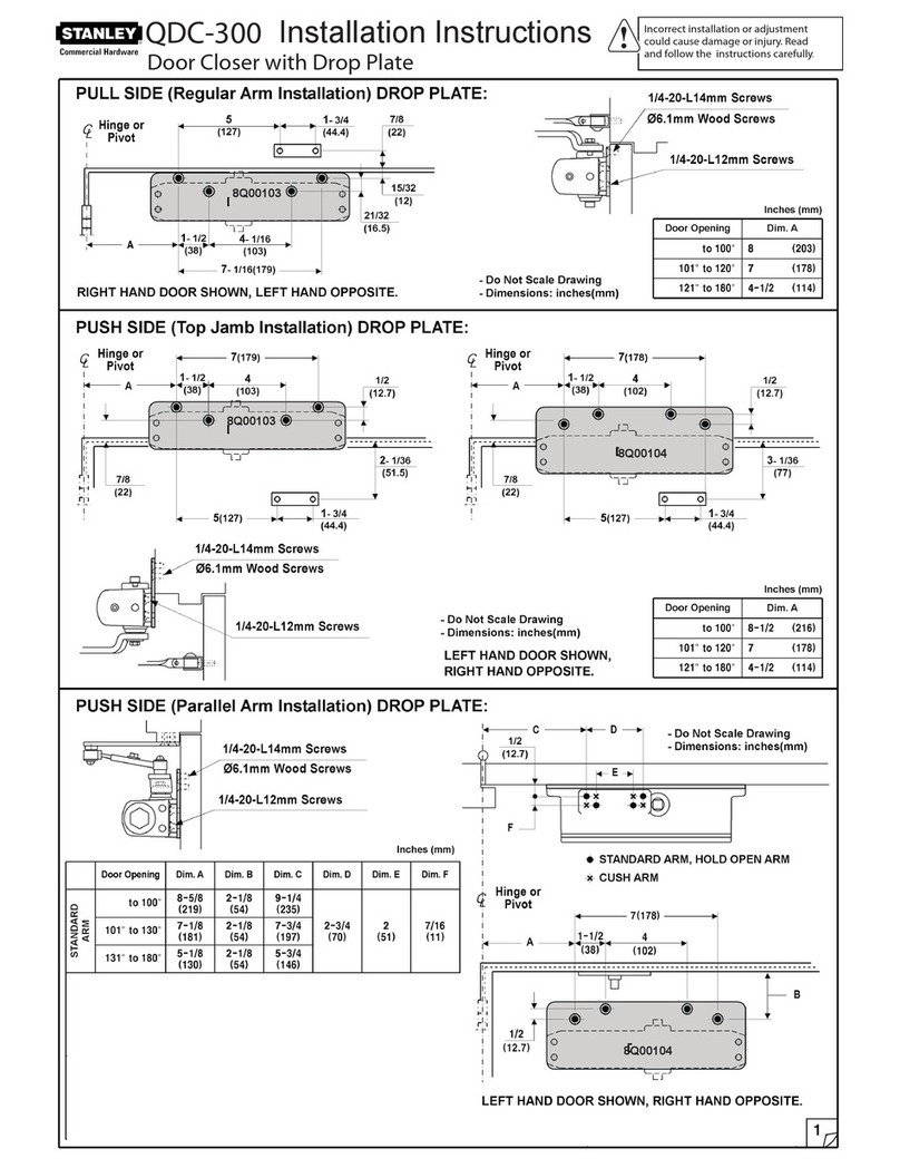
Stanley QDC-300 User manual

Stanley

Stanley QDC-300 User manual

Stanley Dura-Glide 2000AG Series User manual

Stanley

Stanley Dura-Glide 2000AG Series User manual

Stanley Dura-Glide Series Installation guide

Stanley

Stanley Dura-Glide Series Installation guide

Stanley 28064 User manual

Stanley

Stanley 28064 User manual

Stanley Dura-Glide Series User manual

Stanley

Stanley Dura-Glide Series User manual

Stanley M-Force User manual

Stanley

Stanley M-Force User manual

Stanley QED300 User manual

Stanley

Stanley QED300 User manual

Stanley QED300 User manual

Stanley

Stanley QED300 User manual

Stanley MA900ñ Installation instructions

Stanley

Stanley MA900ñ Installation instructions

Stanley QDC-200 User manual

Stanley

Stanley QDC-200 User manual
Popular Door Opening System manuals by other brands

Mobeye Call-Key MCK100 installation manual

Mobeye

Mobeye Call-Key MCK100 installation manual

SALICE Lapis Assembly instructions

SALICE

SALICE Lapis Assembly instructions

Cal-Royal N-F77CVR Installation instruction

Cal-Royal

Cal-Royal N-F77CVR Installation instruction

Scrigno OPEN1000 Assembly manual

Scrigno

Scrigno OPEN1000 Assembly manual

BFT WIND RMB 130B 200 installation manual

BFT

BFT WIND RMB 130B 200 installation manual

Alecto ADI-250 user manual

Alecto

Alecto ADI-250 user manual

Besam Swingmaster MP Installation, adjustment and maintenance instructions

Besam

Besam Swingmaster MP Installation, adjustment and maintenance instructions

Assa Abloy SARGENT 1431 Series instructions

Assa Abloy

Assa Abloy SARGENT 1431 Series instructions

GAL MOVFR Quick setup

GAL

GAL MOVFR Quick setup

Häfele Finetta T 70 VF manual

Häfele

Häfele Finetta T 70 VF manual

AGS D-PL Instructions for fitting, operating and maintenance

AGS

AGS D-PL Instructions for fitting, operating and maintenance

WITTUR Hydra Plus UD300 Instruction handbook

WITTUR

WITTUR Hydra Plus UD300 Instruction handbook

Alutech TR-3019-230E-ICU Assembly and operation manual

Alutech

Alutech TR-3019-230E-ICU Assembly and operation manual

Pamex KT-INP35 Installation instruction

Pamex

Pamex KT-INP35 Installation instruction

MPC ATD ACTUATOR 50 ATD-313186 Operating and OPERATING AND INSTALLATION Manual

MPC

MPC ATD ACTUATOR 50 ATD-313186 Operating and OPERATING AND INSTALLATION Manual

Chamberlain T user guide

Chamberlain

Chamberlain T user guide

Dorma MUTO COMFORT M DORMOTION 50 Mounting instruction

Dorma

Dorma MUTO COMFORT M DORMOTION 50 Mounting instruction

Fireco Dorgard operating guide

Fireco

Fireco Dorgard operating guide

manuals.online logo
manuals.online logoBrands
  • About & Mission
  • Contact us
  • Privacy Policy
  • Terms and Conditions

Copyright 2025 Manuals.Online. All Rights Reserved.

(1) Disassemble Channel and Touchbar
Q Option Upgrade Kit Installation Instructions
QSRK5267 / QSVK5268 Conversion Kits Page 1 of 3
B12/4/200805269-11-000
REVDATEDRWG
Remove 2 screws on the bottom
side of the chassis/channel
(#8-32MS)
1.1
1.4
Remove 4 touchbar screws
(#8-32MS, 2 screws per side)
1.5
Loosen set screw
Slide filler out to allow access
1.2
1.3
Q Option Upgrade Kit Installation Instructions
QSRK5267 / QSVK5268 Conversion Kits
Note: Hex-dogging rim assembly is shown as example only.
(2) Install Touchbar Switch Assembly and Route Wires Mount Q Touchbar Switch with 2 screws (#8-32MS)
provided. Use plastic washers as spacers in-between the
assembly and bracket.
Route harness as shown, keeping it
clear of lower lip to avoid pinching.
Plastic
Washers
Q Touchbar Switch
Assembly
(wires not shown)
2 Screws
(#8-32MS) Route harness through 2 holes at
either end of subplate as shown
and pull it snug.
2.4
Route harness up through lock side filler as
shown. Keep clear of moving parts and
cover.
Dress harness clear of lever arm
and lower lip to avoid pinching.
*Route harness through wire
hole in chassis. Keep clear
of moving parts.
2.1
2.3
2.5
2.6
2.2
2.6
VERTICAL
(2203, 2703, 2803)
or
RIM
(2103)
( * - If no hole in chassis available,
disassemble and drill a thru hole)
Q Option Upgrade Kit Installation Instructions
QSRK5267 / QSVK5268 Conversion Kits Page 2 of 3
B12/4/200805269-11-000
REVDATEDRWG
Position harness in center and tape
down underneath subplate.
(RIM)
(VERTICAL)
.925”
#7 Drill (ǿ.201”)
for RHRB device
#7 Drill (ǿ.201”)
for LHRB device
Lower Lip
Lever Arm
Note: ELR assembly is shown as example only.
Mount and adjust Bolt & Nut appropriately
for switch activation.
Route harness through
switch bracket.
For RIM applications (2103)
(3) Install Latchbolt Switch Assembly
Q Option Upgrade Kit Installation Instructions
QSRK5267 / QSVK5268 Conversion Kits Page 3 of 3
B12/4/200805269-11-000
REVDATEDRWG
* Mount Q Rim Latchbolt Switch
Assembly to chassis with 2 screws
(#8-32MS) provided.
3.1 ** Mount Q Vertical Latchbolt Switch
Assembly to chassis with 2 screws
(#8-32MS) provided. Keep existing
cam bracket assembly held in place
while adding this assembly.
3.1
Dress harnesses as
shown, keeping them
clear of moving parts.
Secure harnesses with
cable clamp or tape to
top of chassis.
(4) Reassemble device by reversing steps 1.1 to 1.5
Note: Refer to EXQ trim installation instructions for
wire connections.
3.2
3.2
Q Vertical Latchbolt Switch
Assembly
(wires not shown)
Dress harnesses as
shown, keeping them
clear of moving parts.
Secure harnesses with
cable clamp or tape to
top of chassis.
For Vertical applications (2203, 2703, 2803)
(3) Install Latchbolt Switch Assembly
* Note: Switch leaf should be positioned under
backside of latchbolt when mounted.
RHRB handing is shown.
Mount switch on opposite
side for LHRB. ** Note: Switch leaf should be positioned in
front of rod carriage features when mounted.
Note: ELR assembly is shown as example only.
Q RIM Latchbolt Switch Assembly
(wires not shown)
LHRB handing is shown.
Mount switch on opposite
side for RHRB.