Kobold NGM-HART User manual

Operating Instructions
for
Configuration Set/HART®-Modem
Model: NGM-HART

Configuration Set NGM-HART
page 2 NGM-HART K05/0922
We don’t accept warranty and liability claims neither upon this publication nor in
case of improper treatment of the described products.
The document may contain technical inaccuracies and typographical errors. The
content will be revised on a regular basis. These changes will be implemented in
later versions. The described products can be improved and changed at any time
without prior notice.
© Copyright
All rights reserved.
1. Contents
1.Contents ........................................................................................................ 2
2.Note .............................................................................................................. 3
3.Instrument Inspection .................................................................................... 3
4.Installation ..................................................................................................... 4
4.1Hard- and Software requirements ........................................................ 4
4.2Electrical connection ............................................................................ 5
4.3Commissioning .................................................................................... 6
5.Configuration ................................................................................................. 9
5.1Basic Configuration .............................................................................. 9
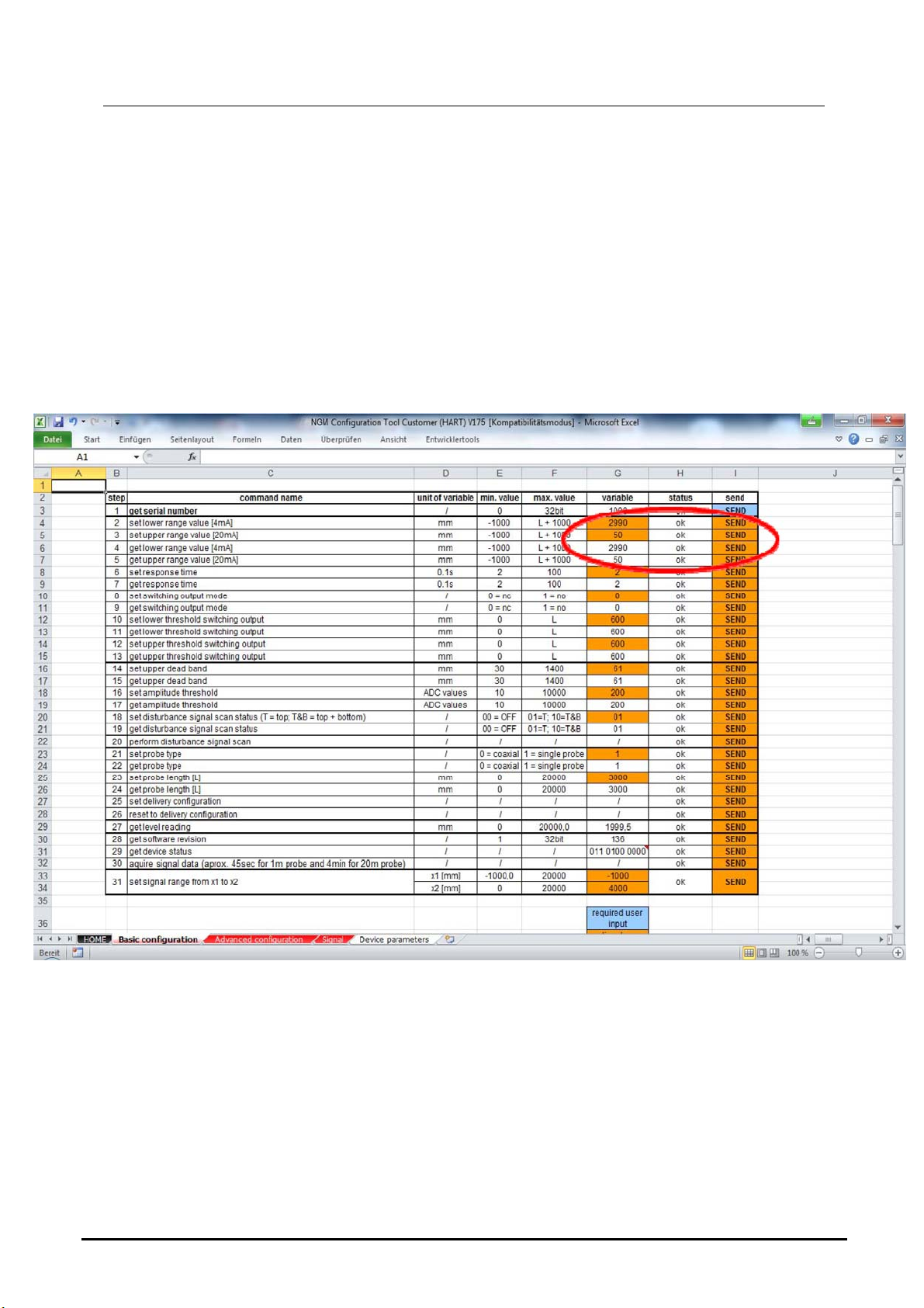
5.2Upper / Lower Range Value ............................................................... 1 0
5.3Response Time .................................................................................. 12
5.4Switching Output Mode ...................................................................... 13
6.Technical Data ............................................................................................ 33
7.Disposal ...................................................................................................... 34
Sold by:
Kobold Messring GmbH
Nordring 22-24
D-65719 Hofheim
Tel.: +49(0)6192-2990
Fax: +49(0)6192-23398
E-Mail: [email protected]
Internet: www.kobold.com

Configuration Set NGM-HART
NGM-HART K05/0922 page 3
2. Note
Please read these operating instructions before unpacking and putting the unit
into operation. Follow the instructions precisely as described herein.
The instruction manuals on our website www.kobold.com are always for currently
manufactured version of our products. Due to technical changes, the instruction
manuals available online may not always correspond to the product version you
have purchased. If you need an instruction manual that corresponds to the
purchased product version, you can request it from us free of charge by email
([email protected]) in PDF format, specifying the relevant invoice number and
serial number. If you wish, the operating instructions can also be sent to you by
post in paper form against an applicable postage fee.
The devices are only to be used, maintained and serviced by persons familiar
with these operating instructions and in accordance with local regulations
applying to Health & Safety and prevention of accidents.
When used in machines, the measuring unit should be used only when the
machines fulfil the EC-machine guidelines.
3. Instrument Inspection
Instruments are inspected before shipping and sent out in perfect condition.
Should damage to a device be visible, we recommend a thorough inspection of
the delivery packaging. In case of damage, please inform your parcel service /
forwarding agent immediately, since they are responsible for damages during
transit.

Configuration Set NGM-HART
page 4 NGM-HART K05/0922
4. Installation
4.1 Hard- and Software requirements
To run the configuration tool the following requirements are necessary:
- Windows PC with available USB port
- Operating system: Windows 10, 8.1, Server 2012, Server 2008 R2, 7, Vista,
Server 2003, XP, ME, 98
- Microsoft Excel version from 2007 (32 Bit and 64 Bit version!)
- Excel-Configuration-Sheet „NGM configuration tool LA V177.xls” (since 01/2022)
- DC supply 24V@30mA (for powering the NGM meter)
- Kobold-HART-Modem with USB connector (Order code HARTCOMM) or any
similar standard HART modems available on the market.
- Communication resistor approx. 250 Ohm
- NGM level probe

Configuration Set NGM-HART
NGM-HART K05/0922 page 5
4.2 Electrical connection
The supplied HART® modem must be connected on the device side via a current
loop resistor (250 Ohm, in the scope of supply).
On the PC side is a normal USB connection required.
Figure 1
The complete wiring is shown in Figure 2:
Figure 2

Configuration Set NGM-HART
page 6 NGM-HART K05/0922
4.3 Commissioning
Before commissioning the hardware drivers for the HART® modem should be
installed.
Note 1!
The current Excel file for configuring the NGM sensor, as well as the
drivers for the modem, can also be downloaded from our homepage
www.kobold.com, under Product search "NGM" / Downloads.
Note 2!
When using the configuration of the NGM with a HART modem, the baud
rate of your USB communication "must" be reduced to 1200 bits/s! This is
set to 9600Bit/s in the standard. If the parameter is not set, no
communication between NGM and EXCEL programming tool can be
established.
After the installation the USB plug of the modem should be plugged into the USB
port and the PC will recognize the modem as “USB Serial Device” and is
assigned a virtual COM port.
After opening the Excel configuration tool, the security level should be set to the
lowest setting for the execution of MACROS.

Configuration Set NGM-HART
NGM-HART K05/0922 page 7
4.3.1 Connection of a NGM Probe to a PC
• Check the COM port assignment of the PC to the USB HART® modem with the
Device Manager
http://www.computerhope.com/issues/ch000833.htm
* In this case COM port 4 has been assigned to the HART® modem

Configuration Set NGM-HART
page 8 NGM-HART K05/0922
4.3.2 First Steps with the Excel Tool
1. Open the Excel file
2. Prerequisite: worksheet is active and the macros are running
(Hint: A restart of the Excel file might help to activate the Macros.)
3. HOME
4. Enter the assigned COM port indicated at the device manager.
For the usage of the Excel tool, a click on the necessary cell activates the
communication and/or parameters can be changed. For re-sending the
command, click on a free cell elsewhere and move back to the required cell. The
OK status has to return for a successful communication.

Configuration Set NGM-HART
NGM-HART K05/0922 page 9
5. Configuration
5.1 Basic Configuration
Establishing a HART® communication:
• Serial number obtainable by clicking on the light blue SEND button J2 in step 1
“get serial number”
• Macros are running
• OK status (H2) disappears and reappears after serial number read out and
shown in G2
If OK status does not reappear, check the connection or the COM port settings
Now the HART® communication is established and the modification of device-
specific parameter as well as the read-out of the echo curve can be performed.

Configuration Set NGM-HART
page 10 NGM-HART K05/0922
5.2 Upper / Lower Range Value
BASIC CONFIGURATION
• Read out actual 4…20mA settings by clicking on I6 and I7
With the command “get lower / upper range value”, the actual 4…20 mA values in mm are shown
after the OK status disappeared and is visible again.
• Change actual 4…20 mA settings by changing the values in G4 and G5 and
clicking on I4 and I5 “set lower / upper range value”
• Verify changes by clicking again on I6 and I7 “get lower / upper range value”

Configuration Set NGM-HART
NGM-HART K05/0922 page 11
Reference point =
0 mm

Configuration Set NGM-HART
page 12 NGM-HART K05/0922
5.3 Response Time
BASIC CONFIGURATION
• Read out actual response time, by clicking on I9.
Field G9 is showing the actual response time multiplied with 0,1ms.
• Change actual response time within a range of 2 … 100 (0,2 … 10 sec) in field
G8 and clicking on I8 “set response time”.
Use high response times for storage tanks with slow level movements. Use low response
times for buffer and process tanks.
Verify changes by clicking again on I9 “get response time”

Configuration Set NGM-HART
NGM-HART K05/0922 page 13
5.4 Switching Output Mode
BASIC CONFIGURATION
• Read out actual switching output mode by clicking on I11
Field G11 is showing the actual switching output mode.
0 = nc = normally closed
1 = no = normally open
Once the probe is powered, the switch output can be open or closed. The standard switch output
mode is set to “normally closed”, as it would open at a power failure for highest safety.
• Change actual switching output mode 0 or 1 in field G10 and clicking on I10 “set
switching output mode”
Verify changes by clicking again on I11 “get switching output mode”

Configuration Set NGM-HART
page 14 NGM-HART K05/0922
5.4.1 Threshold switching output
BASIC CONFIGURATION
• Read out actual lower / upper threshold switching output, by clicking on I13 and
I15.
Field G13/15 indicates the actual lower / upper switching threshold.
With the help of the thresholds, a hysteresis can be programmed to avoid output switching at
turbulent levels. First, the upper threshold must be passed to activate the output then the lower
threshold for deactivation of the output.
• Change actual lower / upper threshold in field G12 / G14 and click on I12 / I14
“set lower / upper threshold switching output mode”.
Verify changes by clicking again on I13 / I15 “get lower /
upper threshold switching output”

Configuration Set NGM-HART
NGM-HART K05/0922 page 15
5.4.2 Upper Dead Band
BASIC CONFIGURATION
• Read out actual upper dead band, by clicking on I17.
Field G17 indicates the actual upper dead band.
With the upper dead band, noisy signals or ringing caused by the installation can be blocked.
Increase the value for cutting signals left to the dead band, whose position is indicated by a green
line. Any signal left to the green line will not be analyzed by the software. Entered values are in
mm and are visible at the echo curve.
• Change actual upper dead band in field G16 and click on I16 “set upper dead
band”.
Verify changes by clicking again on I17 “get upper dead band”

Configuration Set NGM-HART
page 16 NGM-HART K05/0922
5.4.2 Amplitude threshold
BASIC CONFIGURATION
• Read out actual amplitude threshold, by clicking on I19
Field G19 indicates the actual amplitude threshold. Dynamic noise or ringing can be blocked if it is
within the amplitude threshold band. The level reflection should be always 1/3 bigger than the
width of the amplitude threshold band.
• Change actual amplitude threshold in field G18 and click on I18 “set amplitude
threshold”.
Verif
y
chan
g
es b
y
clickin
g
a
g
ain on I19 “
g
et amplitude threshold”

Configuration Set NGM-HART
NGM-HART K05/0922 page 17
5.4.3 Disturbance Signal Scan Status
BASIC CONFIGURATION
• Read out actual disturbance signal scan status by clicking on I21
Field G21 indicates the actual disturbance scan signal status.
00=off, raw echo curve
01=disturbance signal active on top
10=disturbance signal active on top and bottom
• Change actual disturbance signal scan status in field G20 and click on I20 “set
disturbance signal scan status”
• Once changing it to “10” or “01” a disturbance signal scan must be performed
with I22.
Verif
y
chan
g
es b
y
clickin
g
a
g
ain on I21 “
g
et disturbance si
g
nal scan status”

Configuration Set NGM-HART
page 18 NGM-HART K05/0922
5.4.4 Probe Type
BASIC CONFIGURATION
• Read out actual probe type status, by clicking on I24.
Field G24 indicates the actual probe type status.
0= coaxial probe
1= single probe rod or rope
Thresholds are adapted automatically by changing this parameter.
• Change actual probe type in field G23 and click on I23 “set probe type”.
Verif
y
chan
g
es b
y
clickin
g
a
g
ain on I24 “
g
et probe t
y
pe”

Configuration Set NGM-HART
NGM-HART K05/0922 page 19
5.4.5 Probe Length
BASIC CONFIGURATION
• Read out actual probe length, by clicking on I26.
Field G26 indicates the actual probe length in mm.
• Change actual probe length in field G25 and click on I25 “set probe length”.
Verif
y
chan
g
es b
y
clickin
g
a
g
ain on I26 “
g
et probe len
g
th”

Configuration Set NGM-HART
page 20 NGM-HART K05/0922
5.4.6 Set Delivery Configuration
BASIC CONFIGURATION
• Set actual parameters as delivery configuration by clicking on I27
Former delivery configuration parameters will be overwritten!
No reset to factory conditions is possible anymore.
UNDO NOT POSSIBLE!
Table of contents
Other Kobold Transmitter manuals

Kobold
Kobold AFB User manual

Kobold
Kobold AFK-E Series User manual

Kobold
Kobold NEO-7 Series User manual

Kobold
Kobold NGM User manual

Kobold
Kobold TDA Series User manual

Kobold
Kobold NMC User manual

Kobold
Kobold SEN-98 User manual

Kobold
Kobold DF-MA User manual

Kobold
Kobold KAL-7000 Series User manual

Kobold
Kobold DWD User manual