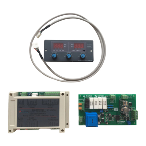
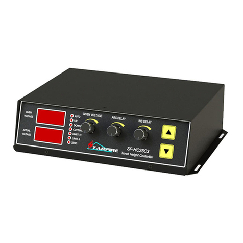
Starfire SF-2400 Owner's manual

BeiJing Starfire Control Technology Co.,Ltd WeChat:18901200180 QQ: 1908817881
1
STARFIRE
SF-2400 Quick User Manual
V2.0
Beijing Starfire Control Technology Co.,Ltd

BeiJing Starfire Control Technology Co.,Ltd WeChat:18901200180 QQ: 1908817881
2
catalogue
The first chapter system operation panel.................................................................................................................... 04
The second chapter main interface ............................................................................................................................... 05
2.1 Main screen button description.......................................................................................................................... 06
2.2 Manual function description .............................................................................................................................. 06
2.3 The menu structure ............................................................................................................................................ 07
The third chapter cutting process.................................................................................................................................. 08
Automatic cutting process diagram................................................................................................................. 08
The first section selection processing graphics...................................................................................................... 09
3.1.1 gallery features........................................................................................................................................ 10
3.1.2 processing file selection .......................................................................................................................... 11
3.1.3 parts option function............................................................................................................................... 12
3.2 Cutting preparation............................................................................................................................................. 15
3.2.1 Parameters to be set before processing ................................................................................................. 14
3.2.2 Main interface, press the space key to enter the processing interface.................................................. 15
3.2.3 Start processing ....................................................................................................................................... 16
The fourth chapter machining process.......................................................................................................................... 17
4.1 to suspend operations ........................................................................................................................................ 18
4.2 after suspend mobile perforation position or cutting position .......................................................................... 19
4.3 the original track back processing ...................................................................................................................... 20
4.4 breakpoints recovery and restore power............................................................................................................ 20
4.4.1. breakpoints recovery.............................................................................................................................. 21
4.5 parts of functions................................................................................................................................................ 22
4.5.1 start parts of functions ............................................................................................................................ 22
4.6 the edge of the thick plate perforation............................................................................................................... 22
The fifth chapter nesting function............................................................................................................................... 24
5.1 The menu function.............................................................................................................................................. 24
5.2 Steel plate teach ................................................................................................................................................. 24
The sixth chapter parameter setting ........................................................................................................................... 25
6.1 Speed parameter ................................................................................................................................................ 26

BeiJing Starfire Control Technology Co.,Ltd WeChat:18901200180 QQ: 1908817881
3
6.2 System parameters ............................................................................................................................................. 26
6.3 Flame parameters............................................................................................................................................... 27
6.4 Plasma parameter............................................................................................................................................... 28
6.5 Control parameters............................................................................................................................................. 29
The seventh chapter The interface definition................................................................................................................. 30
7.1 Wiring instructions.............................................................................................................................................. 31
7.1.1 Input principle ......................................................................................................................................... 31
7.1.2 Default input definition ........................................................................................................................... 32
7.1.3 Output principle ...................................................................................................................................... 33
7.1.4 Default output definition......................................................................................................................... 33
7.2 Interface definition and normally open and normally closed modification ....................................................... 34
7.3 Modify motor direction ...................................................................................................................................... 34
7.4 Definition of motor driver................................................................................................................................... 35
7.5 Differential drive connection .............................................................................................................................. 36
7.6 Total positive drive connection........................................................................................................................... 37
7.7 Panasonic servo connection ............................................................................................................................... 38
The eighth chapter Nc and height controller connection method .............................................................................. 39
8.1 Connect sf-2400 nc with sf-hc25k height controller........................................................................................... 40
8.2 Connect sf-2400 nc with sf-hc25C3 height controller......................................................................................... 41
8.3 Connect sf-2400 nc with sf-hc30A height controller .......................................................................................... 42
The ninth chapter Software upgrade instructions……………………………………………………………43

BeiJing Starfire Control Technology Co.,Ltd WeChat:18901200180 QQ: 1908817881
4
Chapter 1 system operation panel
【F1】-【F8】:Function keys, under different interface, with the corresponding prompt functions;
【F+/PgUP】:to speed up the speed /Under the code interface is up page key,
【F-/PgDn】:to slow down speed /Under the code interface is down page button;
【S+】:Torch up key;
【S-】:Torch down key;
【K1】—【K8】:Shortcut keys, press the screen prompt to open or close the corresponding
output or quickly switch pages;

BeiJing Starfire Control Technology Co.,Ltd WeChat:18901200180 QQ: 1908817881
5
Move the Torch or move the cursor up, down, left, and right;
The enter key to confirm the input value or select the project;
Escape key to exit the current interface or deselect;;
The blank space key, press button to enter automatic processing interface under the main interface;
Start button;
Pause and upgrade keys;

BeiJing Starfire Control Technology Co.,Ltd WeChat:18901200180 QQ: 1908817881
6
Chapter 2 main interface description
2.1 main screen button description
After starting up the system, as shown in the figure below:
Under the main interface, the key functions are as follows:
【F1】Gallery: enter the graphics library, most of which are available in sheet size and hole size. You can also enter the
nesting screen.
【F2】File: select local file, U disk file, file edit, file delete, file import export and other operations.
【F3】Part options: mirror, rotate, starting point, rotate correction, scale, segment selection, etc.
【F4】Process parameters: all parameters can be set here.
【F5】Diagnostic Settings: input/output diagnostics, system Settings, port customization, etc.
【F6】Graphic information: enlarge graphics, view punch points, and cut information display.
【F7】Manual: manually move the machine tool, reset system coordinates, return parameters, and select
breakpoints.
【F8】Modify parameters: it can modify common cutting parameters.
【G】Set cutting mode: press this button to switch the three modes of flame, plasma and demonstration.
【X】Manual speed: sets the manual movement speed.

BeiJing Starfire Control Technology Co.,Ltd WeChat:18901200180 QQ: 1908817881
7
【F】Cutting speed: set the automatic cutting speed.
【T】Preheating time: set the preheating delay.
【N】Slot: the slot size can be set before the cutting operation starts.
【0】Continuous walk: after the function is turned on, press the direction button when manually moving the gun, the
cutting gun will keep walking, and then press the direction button or pause button again to stop.
【 】:Start cutting;
【 】:Pause or stop cutting.
2.2 Manual function description
Under the main screen, press [F2] to enter the manual screen, as shown in the figure below:
[F1] plate calibration: press this key to enter the plate calibration screen.
Steel plate calibration: after entering the rotation calibration interface, move the cutter to the starting position of
plate processing, press [F1] to set the starting point, and the system coordinates will automatically reset, and then
move the cutter to another corner of the same side of the plate, and press [F2] to set the end point, and the system
will automatically rotate the graph. After the correction is completed, the system prompts whether to return to the

BeiJing Starfire Control Technology Co.,Ltd WeChat:18901200180 QQ: 1908817881
8
starting point. If press [ENTER], the system will return to the starting point of the correction. If press [ESC], the system
has no operation and returns to the graphical interface.
[F2] tapping: after pressing this key to input the tapping increment, press the direction key once to cut the gun to a
certain length, and then press it again to cancel the tapping.
[F3] coordinate clearing: coordinate clearing function.
[F4] return parameter: press this key to select "return to reference point" or "return to machine tool origin".
[F5] hand pulse: select the function of hand pulse shifting gun. When this button displays the X-axis or Y-axis, rotate
the knob to move the cutting gun.
[F6] find the breakpoint: if the cutting was not completed last time, press this button. After the breakpoint is found,
press the start button to continue cutting.
[F7] contour walk: press this key and the cutter will walk a rectangle along the graph size to detect the cutting range.
2.3 menu structure
Main
F1ShapeLib
F1Nest
F6OK
F2 Files
F1 Disk File
F2 U Disk
F3 Edit File
F4 Del File
F5
CopyToUDisk
F6 New
F7 OK
F3
PartOption
F1 StartPoint
F2 Scale
F3 Array
F4 Angle
F5 SelPierce
F6 EditFile
F7 Revert
F4 Setups
F1 Speed
F2 System
F3 Flame
F4 Plasma
F5 Control
F6
F7 Save
F8 Super
F5 Diagnose
F1 Input
F2 Output
F3 KeyBoard
F4 System
Def
F5 Clear Len
F6
F7 IO Define
F6 Info
F4 Zoom Out
F5 Zoom In
F6 Return
F7 Info
F7
ManualMove
F1Steel
Adjust
F2 StepMove
F3 Zero
F4 Return
F5 Hand
F6 Recover
F7 Frame
F8 Para

BeiJing Starfire Control Technology Co.,Ltd WeChat:18901200180 QQ: 1908817881
9
Chapter 3 cutting process
Automatic cutting process diagram
3.1 select machining graphics
The system can choose file from the system library to choose processing graphics and from the U disk or storage
area into the user processing graphics
3.1.1 gallery function
Press [F1] on the main interface of the system to enter the main screen of gallery function, as shown in the figure
below:

BeiJing Starfire Control Technology Co.,Ltd WeChat:18901200180 QQ: 1908817881
10
Selection of graphic parts:
At present, the system provides 50 graphics units, press the direction key【↑】【↓】【←】【→】to move the highlighted
cursor, select the required graphics, press the [Enter] key or [F6] to confirm, and Enter the graphic parameters
interface after confirmation.
Graphic parameter interface:

BeiJing Starfire Control Technology Co.,Ltd WeChat:18901200180 QQ: 1908817881
11
Press the direction key【↑】【↓】【←】【→】to move the highlighted cursor and modify the graphic parameters.
[F1] artifact: switch to artifact mode.
[F2] hole shape: switch to opening mode, some parts do not have opening mode.
[F6] refresh: after setting the size data, press this key to refresh the graph, and press the arrow key to refresh the
graph automatically.
[F7] confirm: confirm cutting the current graph, and then the system returns to the cutting screen and displays the
selected graph.
3.1.2 selection of processing documents
Press [F2] on the main interface to enter the file management interface, as shown in the figure below:

BeiJing Starfire Control Technology Co.,Ltd WeChat:18901200180 QQ: 1908817881
12
Local file operation:
[F1] native file: displays the native file.
[F2] usb flash drive: displays usb flash drive files.
[F3] edit file: edit the native file at the current cursor.
[F4] delete file: delete the file at the current cursor.
[F5] copy to U disk: copy the file at the current cursor to the external U disk.
[F6] new: create a new file or folder in the root directory.
[F7] confirm: confirm the file processing at the current cursor and return to the cutting screen.
U disk file operation:
Under the file management screen, press [F2] to enter the U disk file interface, as shown in the figure below:

BeiJing Starfire Control Technology Co.,Ltd WeChat:18901200180 QQ: 1908817881
13
[F1] native file: displays the native file.
[F2] usb flash drive: displays usb flash drive files.
[F3] edit file: edit the file at the current cursor.
[F4] delete file: delete the file at the current cursor.
[F5] copy to local: copy the file at the current cursor from the U disk to the local machine.
[F6] new: create a new folder under the root directory of the U disk.
[F7] confirm: confirm the file processing at the current cursor and return to the cutting screen.
Edit current file:
Under the file interface, move the cursor to the file name to be edited, and press [F3] to edit the file.

BeiJing Starfire Control Technology Co.,Ltd WeChat:18901200180 QQ: 1908817881
14
In the edit code:
[F1]insert a line above the current edit line;
[F2] delete the current edit line;
[F3] create a new file;
[F6] preview graphics;
[F7] save documents;
3.1.3 part selection function
Press [F3] on the main interface to enter the part selection interface

BeiJing Starfire Control Technology Co.,Ltd WeChat:18901200180 QQ: 1908817881
15
[F1] select starting point: press this key continuously to select the starting point of cutting gun positioning, and the
sequence is the bottom left corner the upper left corner the upper right corner the lower right corner the center
point.
[F2] scale: set the scale of processed parts. Example: reduce by half, set 0.5; enlarge by twice, set 2.0.
[F3] layout: arrange the processed parts in a matrix. Note that if staggered arrangement is selected, the even rows are
one less than the odd rows.
[F4] graphics rotation: sets the rotation Angle of the graphics.
[F6] code editing: edit the current cutting file.
[F7] graphic restoration: cancel the operations of graph rotation, mirroring, scaling and discharge, and the graph will
be restored to the original state, but the Angle of steel plate correction will not be cleared. If the Angle of steel plate
correction is needed, enter the screen of manual steel plate correction.
[X]X mirror: the figure is mirrored on the X axis.
[Y] Y mirror: the graph is mirrored on the Y-axis.
3.2 preparation for cutting
3.2.1 parameters to be set before processing

BeiJing Starfire Control Technology Co.,Ltd WeChat:18901200180 QQ: 1908817881
16
Cutting mode [G] : press the keyboard key to switch the cutting mode between flame, plasma and
demonstration.
Cutting speed [F] : press the keyboard key , change the value to change the cutting speed, and
press enter to confirm.
Manual speed [X] : press the keyboard key , change the value to change the cutting
speed, and press enter to confirm.
Slot [N] : press the keyboard key , change the value, change the slot size, and press enter
to confirm.
Preheating delay [T] : press the keyboard key , change the value behind to change the preheating
delay, and press enter to confirm.
3.2.2 press the space on the main interface to enter the processing interface
:The blank space key
[F1] fallback: the cutting nozzle returns along the original path (at this time, only a blank line is left without cutting);
[F2] advance: the cutting nozzle advances along the cutting path (only blank line, no cutting);
[F3] return parameter: the cutting nozzle returns to the starting point, that is, the starting point of the current
workpiece;
[F4] select perforation point: after selecting the perforation point, the cutter will automatically move to the selected
perforation point.
[F5] graphic amplification: enlarge graphics;
[F6] increase delay: increase the preheating time by 15 seconds at a time.
[F7] reduce the delay: reduce the preheating time, skip the remaining preheating time, note: the system does not
remember the preheating time.
3.2.3 start processing

BeiJing Starfire Control Technology Co.,Ltd WeChat:18901200180 QQ: 1908817881
17
After selecting the machined parts and setting machining parameters, press the down button on the main
interface. The system interface is as follows:
At this point, press the [Enter] key to start automatic processing. Press the [ESC] key to exit the system and return to
the main interface
At this point, the system starts to work automatically!
During processing, the processing speed can be adjusted at any time according to [F+] [F-]. Point by slow speed,
long by fast speed.

BeiJing Starfire Control Technology Co.,Ltd WeChat:18901200180 QQ: 1908817881
18
Chapter 4 processing
This chapter describes the processing process needs to be carried out in the introduction
4.1 pause operation
During the processing, if there is a break of fire, arc, or other situations that need to be suspended, press the button
and the system will stop working. The interface is as follows:
[F1] back: the cutting nozzle returns along the original path without cutting;
[F2] advance: the cutting nozzle advances along the cutting path without cutting;
[F3] return parameter: the cutting nozzle returns to the starting point, that is, the starting point of the current
workpiece;
[F4] punch points: jump to other punch points;
[F5] graphic amplification: enlarge graphics;
[F6] increase delay: increase the preheating time by 10 seconds at a time;
[F7] end delay: end the preheating time, skip the remaining preheating time;

BeiJing Starfire Control Technology Co.,Ltd WeChat:18901200180 QQ: 1908817881
19
Note: press [F7] to end the preheating delay. At this time, only the current delay will be ended and will not be
recorded into the system. If the current time needs to be remembered as the system preheating delay, press the
end delay (remember at the same time) to start the perforation processing.
Press Continue processing after modification is completed.
4.2 move the punch position or cut position after suspension
After the pause, move the cutter, and then press start, the following interface appears
Press the arrow to select the corresponding function and press to perform the
corresponding action
1) return the same way
Return to the starting point of adjustment at maximum speed, and wait for further operation; At this time can press
the corresponding strong electric function key (such as ignition, preheat perforation, open cut oxygen, etc.).
Suggestion: after preheating, press the key of [perforation], then the system will continue processing from the
breakpoint position.

BeiJing Starfire Control Technology Co.,Ltd WeChat:18901200180 QQ: 1908817881
20
2) cutting return
First perforation, and then along the cutting speed along the line from the current position to adjust the starting point,
do not stop according to the original trajectory to continue processing, a bit like epitaxial perforation, so that the
perforation point more smooth;
3) offset cutting
Punch first, adjust the current coordinate to the coordinate when suspended, and continue processing according to
the original track to realize the function of transfer punch.
Note: 2) and 3) fully preheat (flame condition) before operation, as perforation will occur as soon as operation is
selected.
The normal procedure is to preheat the flame and press the start button to make a choice.
4.3 original track back processing
In the process, if the original track needs to be retreated due to non-cutting, it can be processed as follows:
Press the key to make the running system slow down and stop. The system displays the "pause" mark and
prompts the figure below.
Press the [F1] key to perform the original track regression of the system, and the regression speed is set in the
parameter -- speed -- regression speed.
Table of contents
Other Starfire Controllers manuals
Popular Controllers manuals by other brands
TSUJI ELECTRONICS
TSUJI ELECTRONICS PM16C-16HW2 user manual
Toshiba
Toshiba nv Series instruction manual
Wavelength Electronics
Wavelength Electronics WTC3243 manual
Control Concepts
Control Concepts Fusion Installation & maintenance manual
Siemens
Siemens SIMATIC S7 F manual
SONBEST
SONBEST SM1635B2 user manual
