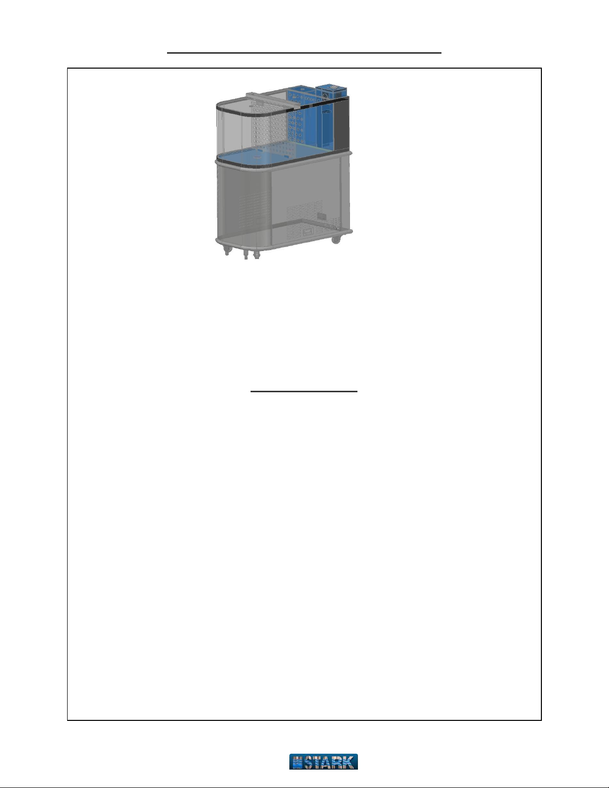
Operating Instructions –Stark Lobster Tank
STARK Products Co., Inc.
Tel. (718) 445-5357
HELPFUL HINTS
SALINITY READING: The hydrometer should float with the surface of the
water in the top area that is shaded green. Too much salt in the tank will cause
the hydrometer to rise so that the green area is out of the water completely.
Too little salt in the tanks causes the green area to sink completely below the
top of the water.
SALT: Only the use of Stark Marine salt is recommended. Lesser quality
salts do not dissolve as well and do not contain all of the essential trace
elements that are necessary for the proper operation of Stark Tanks. Other
salts can cause erratic salinity in the water, burn the lobsters and bind the
pumps. In addition, too much salt may be added because the undisclosed
crystal of poorer quality salts will not show on the hydrometer reading. When
the salt eventually dissolves, the salinity level of the tank will rise, and the
skimmer will pump out more of the poor quality water. The water level will
drop, requiring additional water and salt to be added.
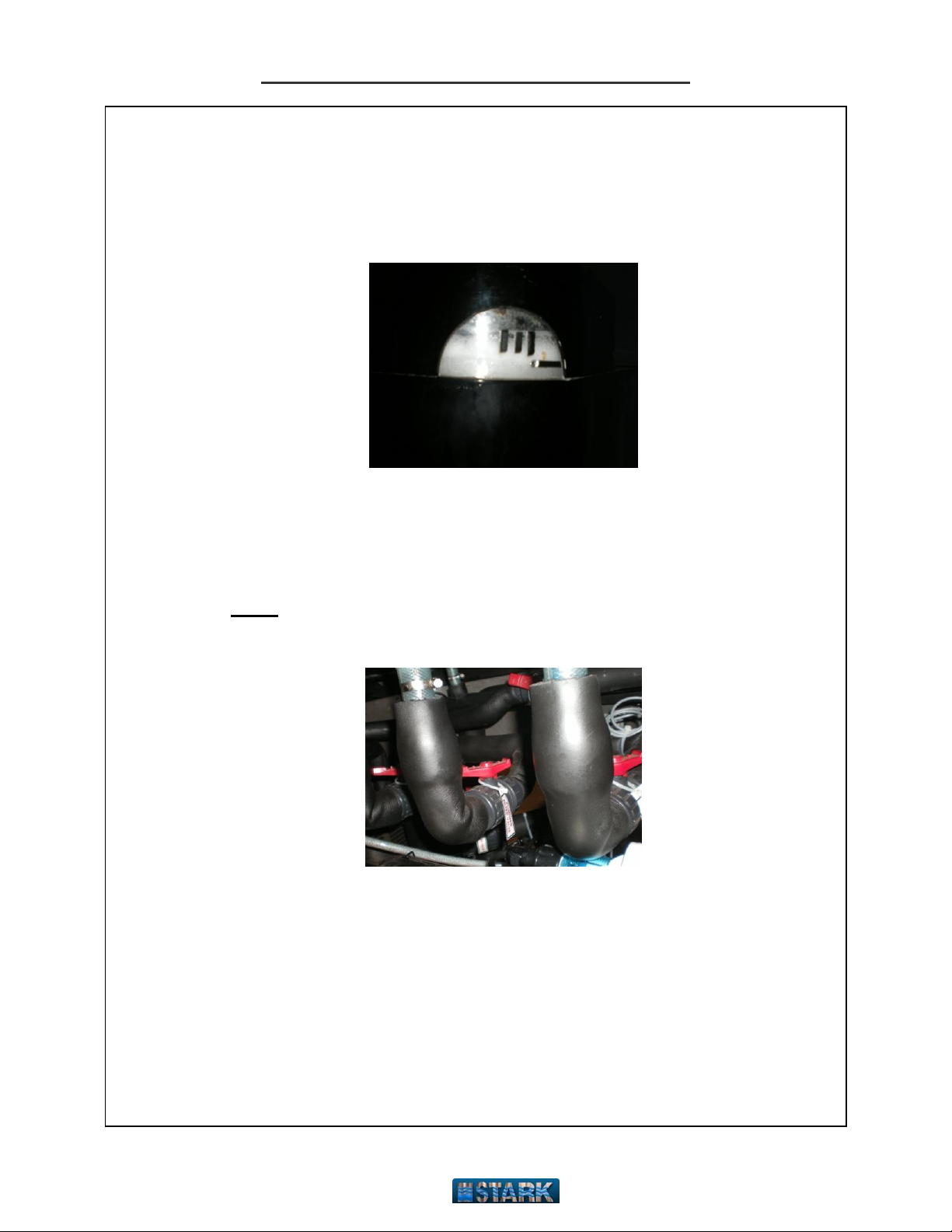
CLEAN the skimmer every week using a baby bottle brush. To clean inside
the chamber, open top white screw cap to gain access.
IF LOBSTERS MUST BE KEPT IN A COOLER, wash the lobsters in salt
water from the tank for three (3) minutes and cover lobsters with a salt water
soaked apron to seal them off from cold air blower. If lobsters have been in
cooler for more than 2 days, DO NOT put them into the tank.
USE ONLY the proper size pre-cut exact fit Stark Filter Pads, Marine Salt
Crystals and Carbon.
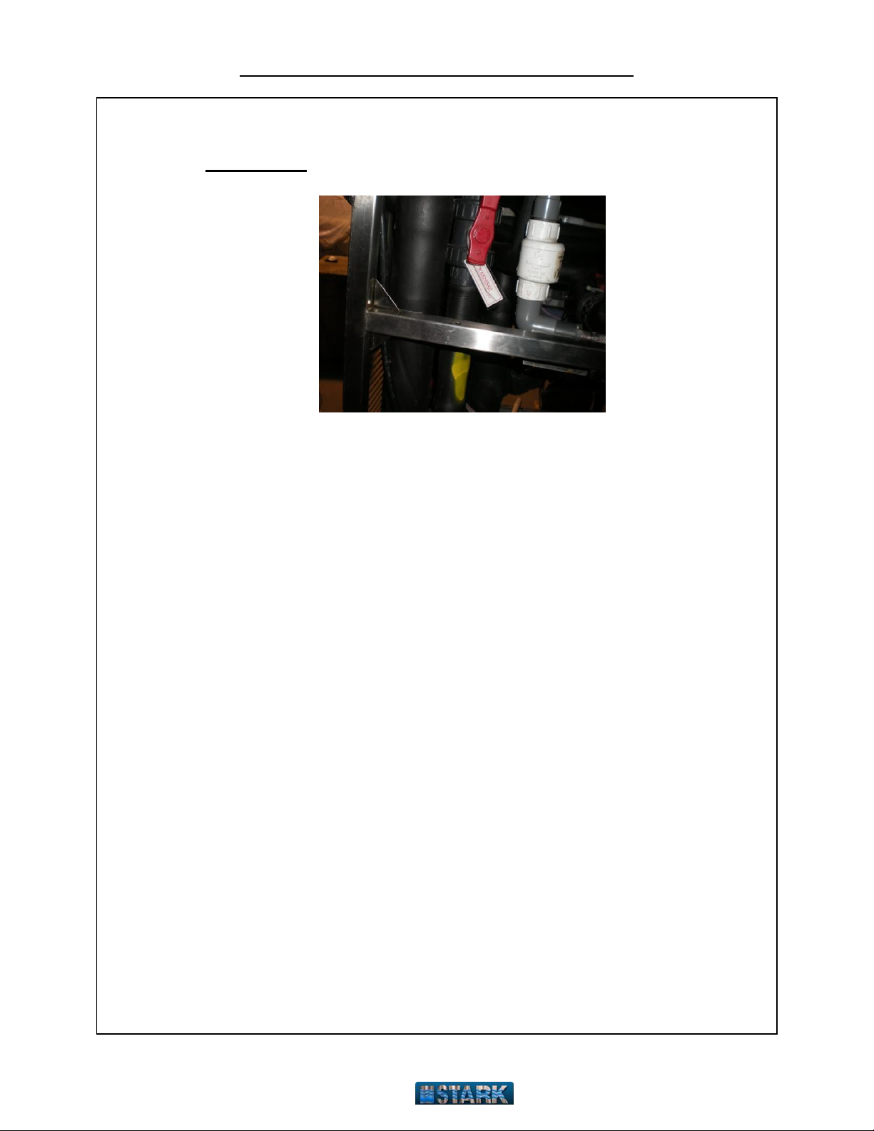
KEEP FILTER SCREENS FREE OF CLOGGING DEBRIS (the screens
are cone-shaped black plastic and are screwed into the bottom of the filter
box). Test these screens periodically for good suction.
CHANGE ACTIVATED CARBON approximately every four (4) weeks to
remove yellow color from the water. Frequency may vary.
NEVER add salt directly to the tank. Always dissolve salt well in a bucket (1
lb to 4 gallons of water) and add slowly to the tank.