AquaCare OD 250 User manual

B-OD.DOC, AUG. 11 - 1 -
Systeme für Aquakultur,
Aquaristik, Labore und
zur Wasseraufbereitung
Systems for aqua culture,
sea water aquaria, labs and
water desalination and purification
Systèmes pour aquacultur,
aquariums eau de mer,
labaratoires et traîtements d’eau
AquaCare
Aquatic Systems Research
AquaCare GmbH & Co. KG
Am Wiesenbusch 11
D-45966 Gladbeck
Tel.: +49-2043-375758-0
Fax: +49-2043-375758-90
http://www.aquacare.de
e-mail: info@aquacare.de
Ozone Destructor OD
D GB
Bedienungsanleitung
Seite 2
Instruction Manual
Page 5
▼Wasserstand Water level
I. Restozonvernichter Ozone destructor
II. Schaumfalle (Option) Foam trap (option)
A Lufteinlass (ozonhaltig) Air inlet (with ozone)
B Luftauslass (ozonfrei) Air outlet (without ozone)
C Sperrwasserablass Locking water drain
D Lufteinlass Air inlet
E Luftauslass Air outlet
F Wassereinlass Water inlet
G Schaumvernichter
Füllstutzen
Foam destruction fluid
inlet
H Wasserablass Water drain
J Sperrwasserzulauf Locking water inlet
1 Basis mit Sperrwasser Base with locking water
2 Aktivkohleteil Activated carbon unit
3 Anzeige Saugung Display „sucking“
4 Anzeige Aktivkohlebett Display „carbon bed“
5 Anzeige Abluftdruck Display „exhaust pressure“
6 Anzeige Wasserstand Display „water level“
7 Entlüftung De-aeration
8 Deckel Cap
9 Kugelhahn Ablass Ball valve drain
10 Revisionsdeckel Instection opening
11 Kugelhahn Ablass Ball valve drain
12 Trennsieb Sieve
13 Ozonanschluss Ozone connector

B-OD.DOC, AUG. 11 - 2 -
Bedienungsanleitung des
AquaCare Restozonvernichters OD
Funktionsprinzip des Restozonvernichters
Ozonhaltige Abluft – z.B. von einem Abschäumer – ist rei-
zend und darf deshalb nicht in die Umwelt gelangen. Im
Restozonvernichter wird durch Aktivkohle Ozon zerstört
und somit die Gefahr gebannt.
Zusätzlich werden durch die Sperrwassersäulen Überdrü-
cke (Abluftleitung (5), Aktivkohlebett(4)) vermieden, die
z.B. den Abschäumer beschädigen können. Ebenfalls wird
bei Ozongeneratoren, die nur mit Unterdruck betrieben
werden dürfen, die Saugung (3) realisiert und zu starke Un-
terdrück vermieden.
Die Luftfeuchtigkeit, die sich normalerweise in der Abluft
eines Abschäumers befindet, schlägt am Aktivkohlebett (2)
nieder und gelangt in den Sperrwasserraum (1). Um einem
Mangel an Sperrwasser durch ungünstige Temperaturver-
hältnisse vorzubeugen ist ein Schwimmerventil im Basisteil
montiert, dass sofort Wasser nachfüllt, wenn ein Mangel
besteht.
Montage des Restozonvernichters
! Schrauben Sie alle Kunststoffteile nur handfest an !
! Beachten Sie die Bedienungsanleitungen der ange-
schlossenen Geräte (Abschäumer, Ozongerät) !
! Anlage nur durch qualifiziertes Personal unter Beach-
tung der lokalen Vorschriften montieren und betreiben
!
! Beachten Sie alle Vorschriften, die sich mit dem Um-
gang mit Ozon ergeben !
Stellen Sie das Gerät auf ebenem Boden auf. Es sollte in der Nähe
des Abschäumers stehen, um die Rohleitungen kurz zu halten.
Abluft des Abschäumers:
die Abluftleitung des Abschäumers muss mit dem Lufteinlass (A)
verbunden werden. Ist eine Schaumfalle montiert, muss sie jedoch
mit dem Lufteinlass (D) verbunden werden; der Luftauslass (E)
der Schaumfalle wird mit dem Lufteinlass (A) des Restozonver-
nichters (I.) verbunden.
Ozonhaltige Luft vom Ozonerzeuger:
In die Leitung Ozongerät-Abschäumer muss ein T-Stück einge-
baut werden. Der freie Anschluss des T-Stücks wird mit dem O-
zonanschluss (13) des Restozonvernichters verbunden.
Ozonfrei Abluft:
Die ozonfreie Abluft muss unbedingt vom Anschluss (B) außer-
halb des Gebäudes geführt werden.
Wasseranschluss:
Das Schwimmerventil der Nachfüllung (J) und der Wassereinlass
der Schaumfalle sollten am Leitungswassernetz angeschlossen
werden (max. 6 bar).
Abwasser:
Der Wasserablass (C) der Basis (1) und der Ablass (H) der
Schaumfalle sollten mit dem Abwassernetz verbunden werden.
Füllen der Aktivkohle:
Als letztes wird die Aktivkohle in den Aktivkohleteil (2) einge-
füllt. Dazu wird der Deckel (8) bzw. die Schaumfalle (II.) demon-
tiert, in dem die Kunststoffschrauben gelöst werden. Nach dem
Einfüllen bauen Sie das Gerät wieder sorgsam zusammen (Dich-
tungen nicht vergessen).
Inbetriebnahme des Restozonvernichters
1. Füllen Sie den Basisteil (1) mit Wasser, über das Schwimmer-
ventil (Anschluss J). Hat der Wasserstand (Anzeige 6) die 0 mm
erreicht, ist das System bis zur Sollhöhe gefüllt.
2. Starten Sie Abschäumer und das Ozongerät. Der Saugdruck
wird an der Anzeige „Saugdruck“ (3) angezeigt. Der Wert muss
immer im negativen Bereich sein, jedoch nicht über -500 mm.
Stimmen Sie den Saugdruck mit den Angaben des Ozongerätes
ab.
3. Die Anzeige „Aktivkohlebett“ (4) gibt den Druck an, der durch
das Aktivkohlebett aufgebaut wird. Notieren Sie sich den Start-
druck. Mit der Zeit, wenn sich das Aktivkohlebett zusetzt oder die
Aktivkohle zersetzt, wird der Druck ansteigen und zeigt somit die
nächste Wartung an.
4. Die Anzeige „Abluft“ (6) gibt den Druck der Abluftleitung an.
Er sollte nur wenige mm über Null sein.
Inbetriebnahme der Schaumfalle (Option)
1. Füllen Sie Wasser einige Zentimeter mit dem Hahn (F) auf und
fügen durch den Füllstutzen (G) ein übliches Schaumhemmmittel.
Wartung des Restozonvernichters
Sollten Verschmutzungen in den Anzeigerohren auftreten, stellen
Sie das Ozongerät ab, warten ca. 15 Minuten, stellen die Wasser-
zufuhr für das Schwimmerventil (J) ab, lassen das Wasser mit
dem Kugelhahn Ablass (9) vollständig ab. Dann können Sie die
Rohre durch die Revisionsöffnungen (10) reinigen, oder Sie kön-
nen die Anzeigerohre an den Verschraubungen vom Gerät trennen
und dann z.B. mit einer Flaschenbürste reinigen.
Steigt der Druck „Aktivkohlebett“ (4) an, ist es Zeit, die Aktiv-
kohle zu wechseln. Dazu nehmen Sie die Anlage außer Betrieb
(Ozongerät abstellen; 15 Minuten warten) und öffnen das Aktiv-
kohlebett (2), indem Sie die Kunststoffschrauben des Deckels (8)
bzw. der Schaumfalle lösen. Die alte Aktivkohle wird herausge-
nommen und gegen neue ausgetauscht. Benutzen Sie nur grobe
Aktivkohle (z.B. Pellets). Nach dem erneuten Zusammenbau
(Dichtung nicht vergessen), kann die Anlage wieder in Betrieb
genommen werden.
Wartung der Schaumfalle
Ist das Wasser in der Schaumfalle verschmutzt, lassen Sie es mit
dem Kugelhahn (11) durch den Ablass (H) ab. Ggf. stellen Sie das
Ozongerät ab, warten 15 Minuten und öffnen die Schaumfalle, in-
dem die Kunststoffschrauben am Deckel (8) entfernt werden. Nun
reinigen Sie die Schaumfalle von innen. Das Sieb (12) ist heraus-
nehmbar und kann ebenfalls gereinigt werden.
Garantie
Es gilt die gesetzliche Gewährleistung. Bei Schäden, die durch
gewaltsame Einwirkungen hervorgerufen wurden, erlischt der
Gewährleistungsanspruch. Für Folgeschäden (z.B. Wasserschä-
den, Tierschäden) kann AquaCare®nicht haftbar gemacht wer-
den.
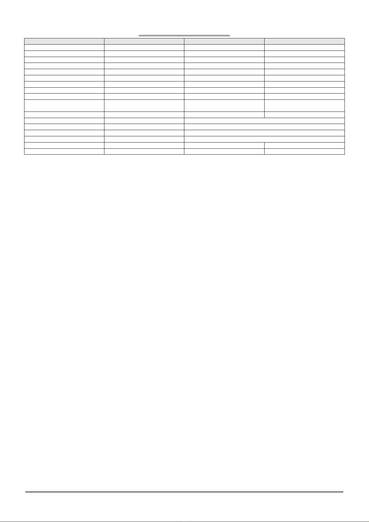
Technische Daten siehe letzte Seite

B-OD.DOC, AUG. 11 - 3 -
Instruction manual of
AquaCare Ozone Destructor OD
Principle of the ozone destructor
Ozone containing exhaust air - e.g. of a skimmer - is harm-
ful and may not arrive therefore not into the environment.
In the ozone destructor ozone is destroyed by activated car-
bon and thus the danger is averted.
Additionally positive pressures (exhaust air tube (5), car-
bon bed (4)) are avoided, which can damage e.g. the skim-
mer. Ozone generators, which operates with negative pres-
sure (sucking tube, 3), are protected, too.
The air humidity, which normally is in the exhaust air of a
skimmer, precipitates at the activated charcoal bed (2) and
arrives into the locking water area (1). To prevent a lack of
locking water by unfavorable conditions of temperature a
float valve is installed in the base that water refills immedi-
ately, if a lack exists.
Mounting the unit
! Screw all plastic parts only very sensitively!
! Please pay attention to all connected units like skim-
mers and ozone generators!
! This unit should be mounted and operated by author-
ized person in accordance with local regulations only!
! Please pay attention to all rules that results with the
operation of ozone!
Stand up the unit on an even surface. The unit should be in
the near of the skimmer, to realize short tube connections.
Exhaust air of the skimmer:
the exhaust air tube of the skimmer must be connected with
the air input (A). Is a foam trap (option, part II.) mounted
the exhaust air tube must be connected with the air inlet
(D). The air outlet (E) of the foam trap must be connected
with the air inlet (A) of the ozone destructor (I.)
Ozone containing air of the ozone generator:
In the tube ozone generator – skimmer a T-piece must be
installed. The open end must be connected with the ozone
connector (13) of the ozone destructor.
Ozone-free exhaust air of the ozone destructor:
A tube must be mounted starting from the union (B) and
ending outside of the building.
Water connection:
The floating valve of the ozone destructor needs an water
connection. Please lay a tube from the tap water to the wa-
ter inlet connection (J). Do not use more the 6 bars.
Waste water:
The drain (C) of the base (1) and the drain (H) of the foam
trap (if installed) should end in a waster water pipe.
Filling up the activated carbon:
At least the activated carbon must be filled in the activated
carbon part (2) of the ozone destructor. Therefore the cap
(8) or the foam trap (II., if installed) must be de-assembled
by unfixing the plastic screws. Now you can put the acti-
vated carbon into the activated carbon unit. Assemble the
whole unit again (please do not forget the sealing).
Putting the ozone destructor into operation
1. Fill up the base part (1) with water by supplying the
floating valve (connection J) with water. The “water level”
increases in the display (6) until zero is reached.
2. Start the skimmer and the ozone generator. The “sucking
pressure” (display 3) is shown. The value must be negative
but not less than –500 mm. Modulate the pressure in accor-
dance to the ozone generator.
3. The display “activated carbon” (4) shows the pressure,
that is established by the activated carbon bed. Please note
this pressure in log book. With the time this pressure will
rise and shows as a consequence the moment for changing
the activated carbon
4. The display “exhaust pressure” (6) shows the pressure in
the exhaust tube. This pressure should only some mm
above zero. Otherwise take a bigger diameter for the ex-
haust tube.
Putting the foam trap into operation
1. Fill some cm water into the foam trap unit (if installed)
by opening the valve (F) and fill some ml of a anti-foaming
fluid through the inlet (G)
Maintenance of the ozone destructor
If dirty is appearing in the displays (3-6), please shut down
the ozone generator, wait about 15 minutes and shut off the
tap water for the floating valve (connector J). Now you can
drain the water by opening the ball valve (9) totally. Please
turn off the union of the displays and take the display tubes
(3-6) out of the unit. You can clean them with water and a
bottle brush.
If the pressure “activated carbon” (4) is increasing you
must change the carbon. Therefore take the ozone generator
out of order (shut off the generator, wait minimum
15 minutes) and open the activated carbon bed (2) by un-
fixing the screws of the cap (8) or the foam trap (II.; if in-
stalled). Take out the old activated carbon and fill fresh
carbon in. Use only activated carbon pellets. If the unit is
assembled again – do not forget the sealing – you can turn
on the whole unit again.
Maintenance of the foam trap
If the water in the foam trap (II.) is dirty, drain it through
the outlet H) with the ball valve (11). Make sure that the
ozone generator is turned off before. Now you can clean
the foam trap with water. The sieve can be taken out and
cleaned, too.
Warranty
You have 24 months warranty on all AquaCare units ex-
cepts spare parts. You have no warranty if parts are broken
by violent.
Technical data see last page

B-OD.DOC, AUG. 11 - 4 -
Technische Daten / Technical data
OD 250 OD 500
Bestellnummer Order number
Maximaler Luftvolumenstrom in m3/h Maximum air flow in m3/h 70 280
Durchmesser in mm Diameter in mm 250 500
Aktivkohlevolumen Volume activated carbon 11 50
Benötigte Grundfläche in cm Needed footprint size 450 × 450 800 × 800
Bauhöhe ohne Schaumfalle in cm Height with foam trap in cm 1710 2000
Bauhöhe mit Schaumfalle in cm Height without foam trap in cm 1960 2200
Ozonanschluss Ozone connection d40 d75
Zuluftanschluss (mit Ozon) Air inlet connection (with ozone) d63 d110
Abluftanschluss (ozonfrei) Exhaust air connection (without
ozone)
d63 d110
Anschluss Ablass Sperrwasser Connection drain d40 d50
Anzeige Wasserstand in mm Display water level -150...+150
Anzeige Saugung in mm Display sucking pressure 40...-550
Anzeige Aktivkohlebett in mm Display activated carbon bed -50...150
Anzeige Abluftleitung in mm Display exhaust air -50...220
Materialien Materials PVC-U, Silikon PVC, Silicone
Masse in kg Weight in kg
www.aquacare.de
This manual suits for next models
1
Table of contents
Languages:
Other AquaCare Aquarium manuals