Stark 66012 Original instruction manual

14” X 40” 4-SPEED 1/2HP 120V WOOD TURNING LATHE
SAVE THIS MANUAL: KEEP THIS MANUAL FOR SAFETY WARNINGS, PRECAUTIONS, ASSEMBLY,
OPERATING, INSPECTION, MAINTENANCE AND CLEANING PROCEDURES. WRITE THE PRODUCT’S
SERIAL NUMBER ON THE BACK OF THE MANUAL NEAR THE ASSEMBLY DIAGRAM (OR MONTH
AND YEAR OF PURCHASE IF PRODUCT HAS NO NUMBER).
OWNER’S MANUAL AND SAFETY INSTRUCTIONS
ITEM: 66012
FOR QUESTIONS PLEASE CALL OUR CUSTOMER SUPPORT: (909) 628 4900 MON-FRI 9AM TO 3PM PST

GENERAL SAFETY WARNINGS
Read all safety warnings and instructions. Failure to follow the warnings and instructions may
result in electric shock, re and/or serious injury. Save all warnings and instructions for future
reference.
SAFETY
The warnings, precautions, and instructions discussed in this instruction manual cannot cover all
possible conditions and situations that may occur. It must be understood by the operator that common
sense and caution are factors which cannot be built into this product, but must be supplied by the
operator. Read carefully and understand all ASSEMBLY AND OPERATION INSTRUCTIONS before
operating. Failure to follow the safety rules and other basic safety precautions may result in serious
personal injury.
Stay alert, watch what you are doing, and use common sense when operating the tool. DO NOT use
the tool while you are tired or under the inuence of drugs, alcohol, or medication.
1
Read and understand all instructions. Failure to follow all instructions may result in serious injury
or property damage.
DO NOT allow persons to operate or assemble the product until they have read this manual and
have developed a thorough understanding of how it works.
DO NOT modify this product in any way. Unauthorized modication may impair the function and/or
safety and could affect the life of the product. There are specic applications for which the product
was designed.
Use the right tool for the job. DO NOT attempt to force small equipment to do the work of larger
industrial equipment. There are certain applications for which this equipment was designed. This
product will be safer and do a better job at the capacity for which it was intended. DO NOT use this
equipment for a purpose for which it was not intended.
Industrial or commercial applications must follow OSHA requirements.
Inspect the work area before each use. Keep work area clean, dry, free of clutter, and well-lit.
Cluttered, wet, or dark work areas can result in injury. Using the product in conned work areas may
put you dangerously close to cutting tools and rotating parts.
DO NOT use the product where there is a risk of causing a re or an explosion; e.g., in the
presence of ammable liquids, gases, or dust. The product can create sparks, which may ignite the
ammable liquids, gases, or dust.
DO NOT allow the product to come into contact with an electrical source. The tool is not
insulated
Keep children and bystanders away from the work area while operating the tool. DO NOT allow
children to handle the product.
Be aware of all power lines, electrical circuits, water pipes, and other mechanical hazards in
your work area. Some of these hazards may be hidden from your view and may cause personal injury
and/or property damage if contacted.
IMPORTANT SAFETY INFORMATION

Dress properly. DO NOT wear loose clothing, dangling objects, or jewellery. Keep your hair, clothing
and gloves away from moving parts. Loose clothes, jewellery, or long hair can be caught in moving parts.
Air vents on the tool often cover moving parts and should be avoided.
Wear the proper personal protective equipment when necessary. Use ANSI Z87.1 compliant safety
goggles (not safety glasses) with side shields, or when needed, a face shield. Use a dust mask in dusty
work conditions. Also use non-skid safety shoes, hard-hat, gloves, dust collection systems, and hearing
protection when appropriate. This applies to all persons in the work area.
DO NOT overreach. Keep proper footing and balance at all times.
2
Check for damaged parts before each use. Carefully check that the product will operate properly and
perform its intended function. Replace damaged or worn parts immediately. Never operate the product
with a damaged part.
DO NOT use a product with a malfunctioning switch. Any power tool that cannot be controlled with
the power switch is dangerous and must be repaired by an authorized service representative
before using.
Disconnect the power/air supply from the product and place the switch in the locked or off
position before making any adjustments, changing accessories, or storing the tool. Such preventive
safety measures reduce the risk of starting the tool accidentally
Use only accessories that are recommended by the manufacturer for use with your product.
Accessories that may be suitable for one product may create a risk of injury when used with another tool.
Never use an accessory that has a lower operating speed or operating pressure than
the tool itself.
Keep guards in place and in working order. Never operate the product without the guards in place.
DO NOT leave the tool running unattended.
Always wear the proper protective equipment including ANSI Z87.1 compliant eye protection, NIOSH
compliant breathing protection, anti-vibration work gloves, steel toed work boots, and a helmet.
Remove adjusting keys and wrenches. Form a habit of making sure keys and wrenches are
removed from the tool before turning it on.
NEVER stand on the tool. Serious injury can occur if the tool is tipped over or if the cutting tool is
contacted.
Maintain tools with care. Keep tools sharp and clean for better and safer performance. Follow
instructions for lubricating and changing accessories.
DO NOT alter or misuse the tool. These tools are precision built. Any alteration or modication not
specied may result in a dangerous condition.
Avoid gaseous areas. Do not operate electric tools in an explosive or gaseous atmosphere. The motor
in this tool normally spark and could react creating a dangerous situation.
WARNING: Before connecting the tool to a power source be sure the voltage supplied is the
same as that specied on the nameplate of the tool. A power source with a voltage greater than
that specied for the tool can result in serious injury and could damage the tool. If in doubt, DO
NOT PLUG THE TOOL IN. Using a power source with a voltage less than the nameplate rating is
harmful to the motor.
IMPORTANT SAFETY INFORMATION

3
MOTOR SPECIFICATIONS
The Wood Lathe is designed to use a 3400 RPM motor only. Do not use a motor that runs faster than
3400 RPM. This Wood Lathe is wired for operation on 110-120 volts, 60Hz alternating current.
To avoid injury from unexpected start-up, do not use blower or washing machine
motors or any motor with an automatic reset overload protector.
CONNECTING TO A POWER SOURCE
This machine must be grounded while in use to protect the operator from electric shock. Plug the power
cord into a 110-120V grounded type outlet protected by a 15-amp dual element time delay fuse or circuit
breaker.
Not all outlets are properly grounded. If you are unsure if your outlet is properly grounded, have it
checked by a qualied technician prior to using this tool.
Failure to properly ground this tool can cause electrocution. If shocked, your
reaction could cause your hands to hit the cutting tool.
Of the power cord is damaged in any way, have it replaced immediately to avoid
shock, injury or re hazard.
MOTOR SPECIFICATIONS AND ELECTRICAL REQUIREMENTS
This Wood Lathe tool is equipped with a 3-cinductor cord and grounding plug. The ground conductor
has a green jacket and is attached to the tool housing at one end and to the ground prong in the
attachment plug on the other end. This plug requires a mating 3-conductor as pictured below. If the outlet
you are planning to use for this power tool is of the 2-prong type, DO NOT REMOVE OR ALTER THE
GROUNDING PRONG IN ANY MANNER. Use an adapter as shown and always connect the grounding
plug to known ground. It is recommended that you have a qualied electrician replace the 2-prong outlet
with a properly grounded 3-prong outlet.
The green grounding plug extending from the adapter must be connected to a
permanent ground such as a properly grounded outlet box.
DIAGRAM AND SPECIFICATIONS

4
The use of any extension cord will cause some loss
of power. To keep this to a minimum and to prevent
overheating and motor burn out, use the table to
determine the minimum wire size (A.W.G.) for an
extension cord. Use one a 3-wire extension cord
which have 3-prong grounding type plugs and 3-pole
receptacles which accept the tool’s plug.
PARTS IDENTIFICATION
ON/OFF SWITCH: Device to turn the Wood Lathe power ON or OFF.
BELT AND PULLEY COVER: Cover for the Belt and Pulley. Open this
cover when changing the speed of the drive center.
DRIVE CENTER: Holds the work piece for turning jobs.
BED RAILS: Rails r moving tail stock and tool rest.
TOOL REST: Holds the tool then turning the work piece.
TOOL REST LOCK KNOB: Lock knob for heigh adjustment of the tool
rest.
TAIL STOCK ASSEMBLY: Works with the drive center to hold the
work piece for turning jobs.
DIAGRAM AND SPECIFICATIONS

5
Separating and checking contents: Separate all loose parts from packing materials and make
sure all parts are accounted for before discarding packing material. If any parts are missing, do not attempt
to assemble the Wood Lathe or plug into a power source. If pieces are missing, contact your distributor
or XtremePowerUS directly.
To avoid re or toxic reaction, never use gasoline, naphtha or any highly volatile solvents.
Apply a coat of paste wax to the table and base to prevent rust. Wipe all parts thoroughly with a clean
dry cloth.
CONTENTS ON BOX:
BODY ASSEMBLY FACEPLATE HEX WRENCH
THIS MACHINE HAS BEEN ASSEMBLED AND TESTED AT THE FACTORY.
ADJUSTING BELT TENSION: The Lathe comes with the belt pre-installed. However, it will need an
adjustment prior to use.
Disconnect the Lathe from power source. Loosen and remove the hex bolt with the adjustable wrench.
Press down on the belt with your hand, the belt should move 1/2” when set properly.
ADJUSTING SPEED: Four spindle speeds of 1100, 1600, 2300 and 3400
RPM are available with the lathe. Chart 1 shows which step of the pulleys the
belt must be placed to obtain four speed. Chart 2 shows the proper speeds
for the work piece.
CHART 1
CHART 2
1. Disconnect the lathe from power source.
2. Open the belt and pulley cover.
3. Loosen the motor pulley by loosening the bolts with adjustable wrench.
4. Place the “V” belt to correct position for desired speed.
5. Adjust “V” belt to proper tension and tighten the motor pulley.
NOTE: For proper belt tension, press down on the belt with your hand.
The belt should move 1/2” when set properly.
OPERATION AND ADJUSTMENTS

6
The tail stock assembly and tool rest are held to the bed with
the lock handle right underneath the bed rails. To move them
to a new position:
1. Disconnect the lathe from power source.
2. Loosen the lock handle with the knob.
3. Slide the tail stock assembly or tool rest along the bed
and re-tighten the lock handle.
MOVING TAIL STOCK ASSEMBLY AND TOOL REST
The lathe must be mounted to a rm supporting surface such
as a stand or workbench when operating. To mount lathe:
1. Disconnect the lathe from power source.
2. Locate and mark where the lathe is to be mounted.
3. Drill four 5/16” diameter holes through the workbench.
MOUNTING THE LATHE
4. Place the lathe on the workbench, aligning holes in the
bed with holes drilled into the workbench.
5. Insert four bolts (sold separately) and tighten.
To remove the tail stock spindle from the tail stock assembly:
1. Disconnect the lathe from power source.
2. Remove the hand wheel by loosening the set screw with
1/8” hex wrench away from the spindle. See Fig. 1
3. Unscrew tail stock spindle from the tail stock assembly.
See Fig. 2
REMOVING TAIL STOCK SPINDLE
Fig. 1
Fig. 2
The Drive Stock center must be removed to attach to the stock
when the spindle is turning. It also needs to be removed when
attaching the faceplate for turning the faceplate. To remove
the drive center from driving spindle.
1. Disconnect the lathe from power source.
2. Using a wrench, hold the at neck of the driving spindle,
then unscrew the drive center counter-clockwise.
REMOVING DRIVE CENTER
OPERATION AND ADJUSTMENTS

7
The faceplate is supplied with your lathe. To install the
faceplate:
1. Disconnect the lathe from power source.
2. Remove the drive center from the driving spindle.
3. Align the center hole of faceplate to the thread of the spindle.
INSTALLING THE FACEPLATE
4. Screw the faceplate into the spindle.
If the centers are not in the lines, make the following
adjustments:
1. Move the tail stock assembly close to the drive center assembly.
2. Lock the tail stock assembly.
3. Loosen the four hex bolts around the drive center.
ALIGNING CENTERS
4. Swing the drive center so that the two centers are in line,
then tighten the bolts.
OPERATION BASICS
The position of your hand on the tool will determine the amount of leverage required. The tool rest general
position is a palm up grip. The rst nger acts as a guide, sliding align the tool rest as the cut is made. The
palm down grip can be utilized for heavy roughing applications. The heel of the hand or the little nger will
serve as a guide.
HAND POSITIONING
The large gouge is used for turning operation. Run the lathe at low speed for this operation. The cut
should start about 2” from the end of the tail stock and will continue back towards the tail stock end. Each
corresponding cut will take place about 3” from the head stock center. You can then roll the gouge in the
opposite direction, which will carry the cut to the end of the spindle.
ROUGHING A SPINDLE CYLINDER
This is used to cut directly into the material, or to make a cut off. Also used for scraping and to set
diameters. It is a narrow tool at 1/8” wide and is shaped to cut its own clearance so the edge won’t be
burned. When used for scraping, it should be backed off regularly to prevent overheating Unlike the
gouge and skew , the parting tool is seldom held with the bevel against the work. As the amount of stock
removed is small, a support for the bevel is not necessary. The tool is simply fed into the work at an angle
(for cutting), or pointed at the work piece center (for scraping).
THE PARTING TOOL
OPERATION AND ADJUSTMENTS

8
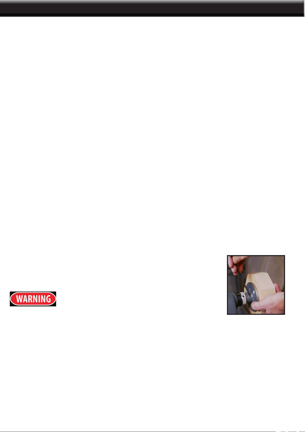
The tool is nearly always used to make nished cute, to cut vees and beads and to square shoulders.
It produces the best nish that can be obtained without a chisel. To avoid dulling, it should be used very
little for scraping. For nish cutting, the skew is held with the cutting edge considerably in advance of the
handle, bevel side down. Keeping the skew well over the work, pull it back until the edge begins to cut,
then swing the handle into position to advance the cut. Both the toe and heel of the skew can be used for
taking light cuts. To avoid burning the tip of the tool, do not penetrate the wood too deeply without cutting
clearances.
USING A SKEW
A shoulder can be the side of a square portion left in the work piece, the side of a turned section, or the
end of the work piece. Most shoulders are perpendicular to the work axis but a shoulder can be at any
angle.
CUTTING A SHOULDER
First, mark the position of the shoulder with a pencil held to the revolving work piece. Then make sizing
cut via the parting tool, placing the cut about 1/16” outside the shoulder position. Cut to within 1/8” of the
depth desired for the area outside the shoulder position. Cut to within 1/8” of the depth desired for the area
outside the shoulder. If the shoulder is shallow, the toe of the skew can be used to make a sizing cut. Do
not go in than 1/8” with the skew unless wider vees are cut to provide clearance for the tool.
Use the gouge to remove any waste stock outside of the shoulder. Smooth the section up to within 1/8”
of the shoulder unless it is more than 1” high, it is best done with the 1/2” skew. First, use the toe of the
skew to remove the shavings from the side of the shoulder down to the nished size. Hold the skew so
the bottom edge of the bevel next to the shoulder will be nearly parallel to the side of the shoulder. Make
sure this is with the cutting edge turned away at the top so that only the extreme toe will do the cutting.
If the cutting edge is at against the shoulder the chisel will run. Start with the handle low and then raise
it to advance the toe into the work. Cut down to nished diameter of the outside area, then clean out the
corner by advancing the heel of the skew into along the surface the outside area. Tilt the cutting edge with
the handle raised up so that only the extreme heel does the cutting if the shoulder is at the end of the work
called “squaring the end”. In this case, reduce the outer portion to a diameter about 1/4” larger than the
tool center diameter, saw off the waste stock later.
Use a pencil mark to indicate edges, then rough it out to within about 1/8” of the desired nish surface
by scraping with the gouge or round nose chisel. If the cove is to wide, sizing cuts can be made to plot
the roughing out. Once it is roughed out, the cove can be nished in two cuts; one from each side to the
bottom center.
CUTTING COVES
At the start of either cut, gouge is held with the handle high and the two sides of the blade held between
the thumb and forenger of the tool rest handle, just above the bevel. Position the ngers ready to roll the
blade into the cove. Hold the blade so that the bevel is at a 90 degree angle to the work axis, with the point
touching the pencil line and pointed into work axis.
From this start, depress the point slightly to start the cut, then continue to move the point down in an arc
toward the bottom center cove. At the same time, roll the chisel uniformly so that at the end of the cut, it
will be at at the bottom of the cove. The object is to keep the extreme point of the gouge doing the cutting
from start to nish. Reverse movements to cut the opposite side.
OPERATION AND ADJUSTMENTS

9
Vee grooves can be cut with the toe or heel of the skew. When the toe is used, the cutting action is
exactly the same as the same as in trimming a shoulder, except the skew is tilted to cut at the required
bevel. Light cuts should be taken down on one side rst, then the other, gradually enlarging the vee to the
required depth and width.
CUTTING VEES
When the heel is used, the skew is rotated down into the work using the tool rest as a pivot. Otherwise,
the cutting position and sequence of cuts is the same. As when using the toe, it is important that cutting
be done only by the extreme end of the cutting edge. If deep vees are planned, it is easier to start them
by making a sizing cut at the center of each vee. Vees can also be scraped with a spear point chisel or
three-sided le.
Make a layout rst to provide a visual pattern to follow while working the turning. The pattern can be laid
out in the same manner as spindle pattens. Templates can be held against the work for visual comparison.
Circles to locate the various critical points can be quickly scribed on the rotating work by using the dividers.
LAYING OUT YOUR PROJECT
The rst step is to remove as much wood as possible by boring into the center with the largest wood bit
available. Be careful to measure in advance the depth to which the drill can be allowed to go.
TURNING THE PROJECT
Next, remove the bulk of the waste by scraping with the round-nose scraper or the bowl gouge. Remove
up to within 1/8” of the nished size in this manner. Finish off the inside the circumference by scraping
with the round nose or left round scraper. Smooth the bottom of the recess by scraping it with a at nose
scraper. Always try to position the part of the tool rest that supports the tool as close to the working surface
as possible.
You can directly mount the faceplate to the work piece by fastening four (or
eight) wood screws (sold separately) to the work piece.
MOUNTING THE WORK PIECE TO THE FACEPLATE
Always make sure the work piece is securely fastened to the faceplate
or between centers. When the faceplate is turning, always make sure
the screw fasteners do not come in contact with the turning tool as work
progresses.
Turning that does not mount between centers require a faceplate for holding the work piece. All work
pieces of this type should be slightly oversized to eliminate roughing cuts and vibration.
FACEPLATE TURNING
OPERATION AND ADJUSTMENTS

10
TROUBLESHOOTING

MAINTAINING YOUR WOOD LATHE
For your own safety, turn the power off and remove the plug from the power source outlet before
maintaining or lubricating your wood lathe. Blow out any dust that may accumulate inside the motor. A
coat of automobile-type wax applied to the rail and center driver will help to keep the surfaces clean. If the
power cord is cut, worn or damaged, do not plug it in and have it repaired or replaced to avoid shock, a
re hazard or serious injuries.
All repairs, electrical or mechanical, should be performed by a trained professional only.
All of the ball bearings are packed with grease at the factory, they require no additional lubrication.
Periodically lubricate the center driver and tailstock assembly.
LUBRICATION
PARTS LIST
11
PARTS LIST

12
PARTS DIAGRAM

13
THE MANUFACTURER AND/OR DISTRIBUTOR HAS PROVIDED THE PARTS LIST AND ASSEMBLY
DIAGRAM IN THIS MANUAL AS A REFERENCE TOOL ONLY. NEITHER THE MANUFACTURER OR
DISTRIBUTOR MAKES ANY REPRESENTATION OR WARRANTY OF ANY KIND TO THE BUYER THAT
HE OR SHE IS QUALIFIED TO MAKE ANY REPAIRS TO THE PRODUCT, OR THAT HE OR SHE IS
QUALIFIED TO REPLACE ANY PARTS OF THE PRODUCT. IN FACT, THE MANUFACTURER AND/OR
DISTRIBUTOR EXPRESSLY STATES THAT ALL REPAIRS AND PARTS REPLACEMENTS SHOULD BE
UNDERTAKEN BY CERTIFIED AND LICENSED TECHNICIANS, AND NOT BY THE BUYER. THE BUYER
ASSUMES ALL RISK AND LIABILITY ARISING OUT OF HIS OR HER REPAIRS TO THE ORIGINAL
PRODUCT OR REPLACEMENT PARTS THERETO, OR ARISING OUT OF HIS OR HER INSTALLATION
OF REPLACEMENT PARTS THERETO.
Record Product’s Serial Number Here:
Note: If product has no serial number, record month and year of purchase instead.
Note: Some parts are listed and shown for illustration purposes only and are not available individually
as replacement parts.
PLEASE READ THE FOLLOWING CAREFULLY
WARRANTY
PRODUCT MADE IN CHINA
Table of contents
Other Stark Industrial Equipment manuals

Stark
Stark TL 7500 Operating instructions

Stark
Stark S-3000 Guide

Stark
Stark 61041 User manual

Stark
Stark 65027 Original instruction manual

Stark
Stark 5030 Operating instructions

Stark
Stark S-500 Guide

Stark
Stark 67001 User manual

Stark
Stark S-2000 Guide

Stark
Stark 75140 Original instruction manual

Stark
Stark RF 900 Operating instructions
Popular Industrial Equipment manuals by other brands

Arbpro
Arbpro LD1 instruction manual

nystrom
nystrom PTX Installation, operation & maintenance manual

Textron
Textron Klauke EK 60VPFTCL manual

APE
APE 475 Operation and maintenance manual

ABB
ABB Relion REX610 installation manual

Marshall Excelsior
Marshall Excelsior MER470 STANDARD KIT Important installation instructions