Stark 5030 Operating instructions

Original
Operating and maintenance
manual
Road Grader (5030)

Sivu 2 / 18
General
Congratulations on the purchase of your STARK Road Grader!
For us, the long lifecycle and efficiency of your new equipment is a priority. To keep the road grader in top working
condition, read this manual carefully before using the equipment.
STARK products are engineered and manufactured in Finland, and each of them is equipped according to the needs of
the customer.
Never let anyone operate or maintain the device without reading this manual carefully! Always make sure that safety
precautions are observed in use and maintenance. Keep this manual for future reference and make sure to hand it over
to a new owner.
The cornerstones of the product development of STARK attachments are quality, durability and economy. The products
are engineered to be high-performing, safe and durable in professional use. Any feedback on our products is welcome
and contributes to the further development of our products. If you have any questions about the use or maintenance of
the road grader, please contact us by e-mail: i[email protected]
Visit our webpage www.stark.fi for the complete product range, including new products.
The manufacturer reserves the right for structural and technical changes without prior notice. Therefore, some pieces of
information given in the manual may have changed after printing this manual.
Read before use
Make sure you know your equipment before you start using it.
Equipment may be operated only by an individual who is thoroughly familiar with its use.
All operators must be properly instructed before use and maintenance of the equipment. Use by
individuals with insufficient instructions may pose serious risks to the operators themselves, to the
environment and the equipment.
When coupling the attachment to the base machine, make sure:
-that all locking cotters are intact and in order
-there is no pressure in the hydraulic system
-that hydraulic hoses are intact
-there is no skin contact to hydraulic oil when connecting hydraulic hoses
-not to pull by the hydraulic hoses, but only by the hydraulic fitting
During operation, pay attention to:
-safe, appropriate travel speed
-other traffic, people and animals
-danger zones and objects that block your view
-children
NEVER use the machine if there is someone in the danger zone.
NEVER go under the attachment.

Sivu 3 / 18
Table of contents
General.................................................................................................................................................2
Read before use ...................................................................................................................................2
1. DECLARATION OF CONFORMITY......................................................................................................4
2. PURPOSE OF USE..............................................................................................................................5
3. SAFETY PRECAUTIONS......................................................................................................................5
4. IDENTIFICATION INFORMATION AND SPAREPARTS ........................................................................6
4.1. Identification plate ............................................................................................................................ 6
4.2. Maintenance services........................................................................................................................ 6
5. MAIN PARTS OF THE ROAD GRADER ...............................................................................................7
6. ATTACHING THE ROAD GRADER......................................................................................................8
6.1. Attaching the road grader to the base machine ............................................................................... 8
7. OPERATING THE ROAD GRADER ......................................................................................................9
7.1. Operating instructions....................................................................................................................... 9
7.2. Grading adjustmets ........................................................................................................................... 9
7.3. Adjusting the blades........................................................................................................................ 11
7.4. Detaching the road grader .............................................................................................................. 12
7.5. Accessories ...................................................................................................................................... 12
8. MAINTAINING THE ROAD GRADER ................................................................................................13
8.1. General safety precautions for the use and maintenance.............................................................. 13
8.2. Minimum requirements of the base machine................................................................................. 13
8.3. Tightening torque............................................................................................................................ 13
8.4. Daily maintenance........................................................................................................................... 14
8.5. Maintenance after every 10 hours.................................................................................................. 14
8.6. Maintenance after 50 hours or weekly ........................................................................................... 14
8.7. Lubrication points............................................................................................................................ 15
9. HYDRAULICS...................................................................................................................................17
9.1. 10-hose hydraulics........................................................................................................................... 17
10. WARRANTY POLICY ......................................................................................................................18

Sivu 4 / 18
1. DECLARATION OF CONFORMITY
The original manufacturer’s EC declaration of conformity:
Generic product name: Road grader
Models: TL 7500
Manufacturer:
Lametal Ltd
Kaskenviertäjäntie 2 73100 LAPINLAHTI, Finland
tel. +358 17 731 565
Declares that the above-mentioned equipment meets the provisions of Directive 2006/42/EC on machinery and, where
applicable, comply with the standards
•SFS-EN ISO 12100-1,
•SFS-EN ISO 12100-2
•SFS-EN 1050
The person authorized to compile technical documentation:
Lassi Mehtonen
Managing director
Kaskenviertäjäntie 2
73100 Lapinlahti, FINLAND

Sivu 5 / 18
2. PURPOSE OF USE
STARK Road graders are used for grading gravel roads and flat areas and for transferring ice (removal of packed snow).
The device can also be used to shape and align fields.
3. SAFETY PRECAUTIONS
Make sure you know your equipment before you start using it. Equipment may be operated only
by an individual who is thoroughly familiar with its use.
Before connecting hydraulics to the base machine, make sure that:
-there is no-one between the attachment and the base machine
-the base machine is turned off and the parking brake is on.
When coupling the attachment to the base machine, make sure that:
-all locking cotters are intact and in order
-hydraulic hoses are intact
-there is no skin contact to hydraulic oil when connecting hydraulic hoses
-you do not to pull by the hydraulic hoses, but only by the hydraulic fitting.
During operation, pay attention to:
-safe, appropriate travel speed
-other traffic, people and animals
-danger zones and objects that block your view
-children
-use of turn signal when driving
NEVER use the machine, if there is someone in the danger zone
NEVER go under the attachment
During maintenance, the hydraulics of the base machine MUST be turned off. The base machine MUST also be turned
off and the parking brake MUST be applied. The equipment must be properly supported, if maintenance can only be
performed by going under the equipment. Never go under the equipment if it is not properly supported.
Daily maintenance:
-check general condition of structures, make repairs if needed
-check the hydraulic hoses and fittings, and replace damaged parts
After every 50 hours of operation:
-lubricate points specified in later section of this manual
-check all bolts and nuts for tightness
Check all bolts, nuts and hydraulic fittings for tightness after the first day of operation!
If the equipment is not likely to be used for a longer period, clean it thoroughly after use and lubricate as instructed.
WARNING! Pressurized hydraulic hoses and components!

Sivu 6 / 18
4. IDENTIFICATION INFORMATION AND
SPAREPARTS
4.1. Identification plate
Identification plate is placed on the side of the equipment. The plate includes contact information, machine type, year of
manufacture, serial number and weight. (See an example of an identification plate in picture 1 below).
The first four numbers in the serial number indicate the month and year of manufacture (month first). The remaining five
numbers constitute the machine tracking number, which is stored in the manufacturer’s database (13971 in the example
below).
Picture 1. Identification plate
Take down the machine type and the serial number of your road grader:
Product and model _______________________________Serial number___________________________________
4.2. Maintenance services
When replacing parts, use original, manufacturer spare parts only. By using original spare parts, you ensure dependable
operation of the road grader and comply with the warranty policy. To facilitate the supply of spare parts, always inform
the manufacturer/retailer of the model and serial number of the road grader (marked in the identification plate) when you
order spare parts.
For more information on maintenance and spare parts, please contact the STARK maintenance and spare part services
or your retailer.
Contact information for STARK maintenance services:
tel. +358 (0)17 731 565, e-mail info@stark.fi
tel. +358 (0)44 758 6221, e-mail parts@stark.fi

Sivu 7 / 18
5. MAIN PARTS OF THE ROAD GRADER
Picture 2. Main parts of the road grader
1) Frame of the road grader
2) Shaft of the windrow spreader
3) Front wing
4) Middle wing
5) Back wing
6) Windrow spreader
7) Lift arm
8) Box

Sivu 8 / 18
6. ATTACHING THE ROAD GRADER
When attaching the road grader for the first time, make sure it is compatible with the base machine by following the
instructions below. Always check the compatibility when attaching the road grader to a new base machine.
Make sure that the base machine allows installation of the road grader. Minimum requirements of the base machine:
-Minimum weight of 6,000 kg
-With wireless controller, 1 x 2-way hydraulic valve
-7-pin trailer light plug
-3-pin power socket
-Towing hook
-Hydraulic output max. 50 L /min and 210 bar
6.1. Attaching the road grader to the base machine
Before using the road grader spreader, MAKE SURE all locking cotters and pins are secured and intact.
When coupling the road grader to the base machine, please pay attention to the instructions on the use of the base
machine.
1) Make sure that the attachment and the base machine are compatible in terms of mechanical solutions,
hydraulics and electricity.
2) The road grader is connected to the tractor’s towing hook and hydraulic system.
3) Turn off the base machine, engage the parking brake and release pressure from the hydraulic jacks.
4) Connect the grader to the base machine’s towing hook and move the tractor arms to lower position.
5) Connect the hydraulic connectors to the base machine and make sure that the grader does not damage the
cable connectors while in motion.
6) Connect the power socket/plugs.
7) During the first use, exercise extreme caution when using the product and make sure that grader does not
collide with the tractor when in motion. The warranty does not cover damage caused by an improperly installed
device.
8) When the attachment is new, bolts, nuts and connectors can loosen up among first hours of operation.
Retighten them after the first day of operating the attachment.

Sivu 9 / 18
7. OPERATING THE ROAD GRADER
Before operating the road grader, make sure:
-the road grader is installed correctly
-all locking pins are in place
-hydraulic hoses are connected right and properly
-hoses are intact
-there are no oil leaks
-all functions are working properly
-learn to operate the road grader in a closed area before actually using the device
7.1. Operating instructions
1. Make sure that the attachment and the base machine are compatible in terms of mechanical solutions,
hydraulics and electricity
2. The road grader is attached to the towing hook on the base machine. Engage the parking brake. Attach the
road grader to the base machine.
3. Turn off the base machine and make sure the parking brake is applied.
4. Make sure there is no pressure in the base machine hydraulic system. When connecting, always make sure the
hydraulic connectors are clean and the hoses are intact.
5. Check carefully the attachment’s, the base machine’s and the fitting’s trajectory for collision. Make sure that the
hydraulic hoses and attachments have enough space. If needed change places of the hoses in the base
machine.
6. Stay alert for any abnormal behavior and oil leaks also during driving.
7.2. Grading adjustmets
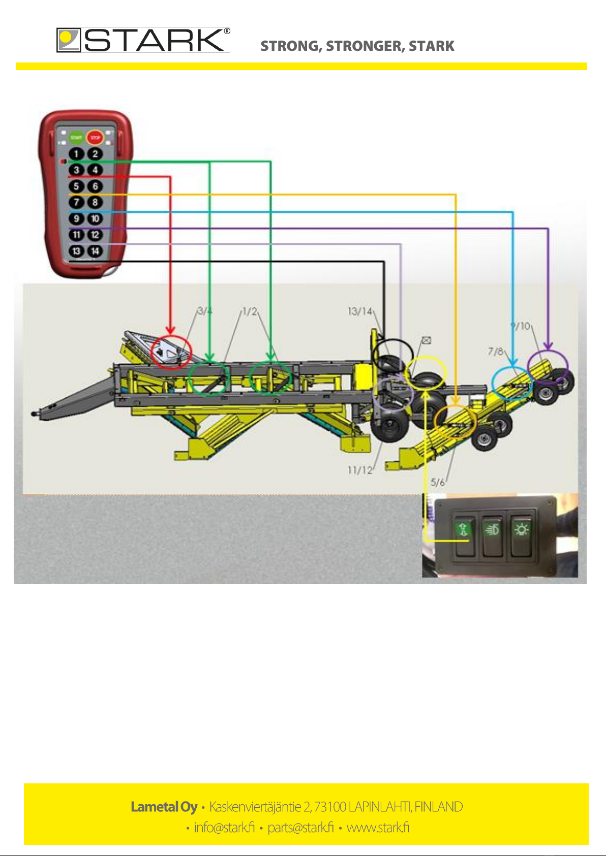
Grader is equipped with a remote controller, which allows to control all actions with one 2-way section valve. Controller,
it’s fastener and power socket are added to the base machine.
Operating the controller:
-Attach electricity from the base machine with a 3-pin power socket.
-Turn the controller on with a green START-button (must be done every time the power supply stops).
-Operate controllers’ buttons simultaneously with the base machine’s directional valve.
-When transferring the grader turn off the controller with a red STOP-button.
-The warning light of the controller lights up 100 hours before the batteries are empty.
-If there is an error in controller, recode it.
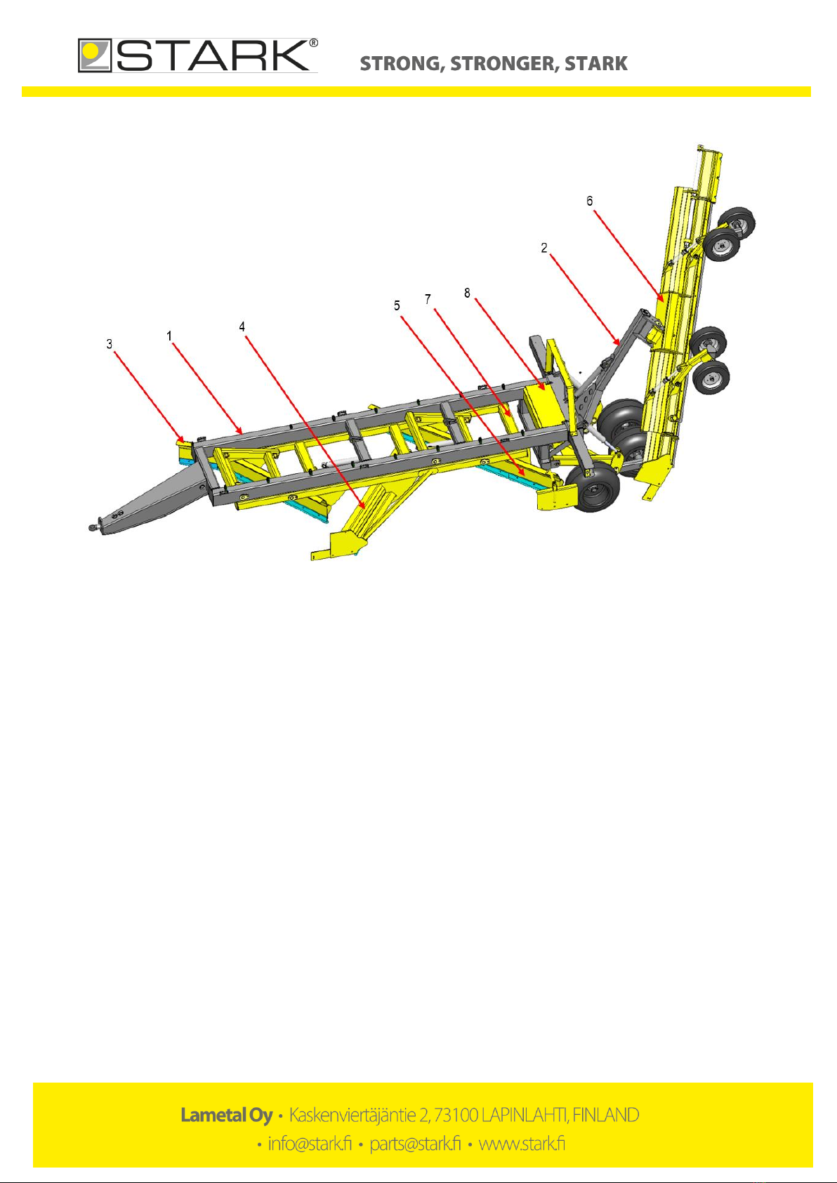
Functions of the controller (picture 3):
-Main blades of the grader lift/descent with buttons 1 and 2. When transferring the road grader keep main
blades all the way up.
-Main blades’tilt can be adjusted with buttons 13/14 and 11/12. Use slope pointer to check the slope of the
grader.
-Windrow blade lifts/descents with arrow buttons of controller box. When transferring the road grader keep
windrow spreader all the way up.
-Windrow blade’s tilt can be adjusted with buttons 5/6 and 7/8. Windrow’s height depends on the depth of the
grading. If there is sand coming out of windrow blade, it is too close to the road. Windrow spreader is adjusted
correctly when rocks come out of windrow blade and transferred material spreads evenly on the road.
-Width of the windrow blade can be adjusted with buttons 9 and 10.
-If grader is equipped with side blade, it can be adjusted with buttons 3 and 4. When transferring the road
grader keep side blades all the way up.

Sivu 10 / 18
Picture 3. Functions for remote controller and controller box

Sivu 11 / 18
7.3. Adjusting the blades
Edge of the blade should be 15–45 mm lower than the blade frame. Blades need to be adjusted at the latest when the
blade edge is less than 10 mm lower than the blade frame (picture 4). Do not adjust the blades more than 50 mm lower
than the blade frame.
Picture 4. Minimum distance of the blade to the frame
Blades can be adjusted three times. Each time there will be about 45 mm wear edge on the blade. First when the blade
is new, it is in the position of picture 5. When the blade edge wears out it is lowered and attached from the upper holes
of the blade (picture 6). Next time the blade is turned and again attached from the lower holes (picture 7). When the
blade edge wears out again it is lowered by attaching it from the upper holes (picture 8). When the blade edge wears out
in this position, it needs to be replaced.
Picture 5. New blade
Picture 6. Lowered blade
Min. 10 mm

Sivu 12 / 18
Picture 7. Turned blade
Picture 8. Turned and lowered blade
7.4. Detaching the road grader
-When you disconnect the blade assembly from the tractor, lower the assembly on a flat surface and rest it on
the blades.
-Rest the blades on top of strong support brackets.
-When transferring road grader for long distances, windrow spreader must be secured to upwards stance with e.
g. a cargo strap.
-Turn off the base machine and remove pressure from the hydraulic hoses. This facilitates the re-installation.
-Disconnect the hydraulic quick connectors and sockets and protect them.
-Start the tractor and remove the blade assembly from the tractor hook-up.
7.5. Accessories
The following accessories are available for the road grader:
-Flat-, pin- and hardened metal blade set
-Ditch wing 1500/1800
-Hydraulic extension for the windrow spreader
-Pin blade set for the ditch wing

Sivu 13 / 18
8. MAINTAINING THE ROAD GRADER
8.1. General safety precautions for the use and maintenance
-Comply with the applicable laws and regulations and the instructions in this manual
-Never go under the road grader if it is not supported
-Always put on the base machine’s parking brake before any servicing on the road grader.
-Use only tools which are in good condition.
-Watch out for pressurized hydraulic hoses and components.
-Make sure there is no pressure in the hydraulic system. Take into account the pressure accumulator
-Do not let hydraulic fluids or lubricants to the ground.
-Wear appropriate personal protective equipment.
-Pay attention to the attachment’s width, weight and other factors that can alter the operating experience. Adjust
the driving speed according to circumstances. Make sure there are no other people in the working area.
8.2. Minimum requirements of the base machine
-Minimum weight of 6,000 kg
-With wireless controller, 1 x 2-way hydraulic valve
-7-pin trailer light plug
-3-pin power socket
-Towing hook
The road grader is attached to the towing hook of the base machine.
1. Attach the road grader to the base machine and move the tractor arms to lower position.
2. Turn off the base machine, engage the parking the break and remove pressure from the hydraulic connectors.
3. Attach the hydraulic connectors to the base machine and make sure that the road grader won’t damage the
hoses.
4. Connect the power socket/plugs.
When operating the grader for the first time, be extremely cautious and make sure that the grader doesn’t collide with the
base machine. Warranty does not cover damages caused by incorrect installation.
8.3. Tightening torque
Nm (Strenght 8.8)
M4
3,3
M5
6,5
M6
11,3
M8
27,3
M10
54
M12
93
M14
148
M16
230
M18
329
M20
464
M22
634
M24
798
M27
1176
M30
1597
M33
2161
M36
2778
M39
3597
Table 1. Tightening torque

Sivu 14 / 18
8.4. Daily maintenance
It is important to perform a daily visual inspection of the road grader for early detection of possible faults and to prevent
further damage. Inspect the following items on the road grader daily:
-Hydraulic hoses and components for possible leaks
-General mechanical condition
8.5. Maintenance after every 10 hours
-Lubricate marked components (see a later section for instructions)
-Check the bolts for tightness (table 1)
8.6. Maintenance after 50 hours or weekly
-Check the bolts for the tightness (table 1)
-Lubrication, recommended quality NLGI-2 grade grease or equivalent (see a later section for instructions)
-Check the mechanical condition of the road grader for distortion or rupture
-Check the drawbar eye for wear and tear
-Apply oil to the steel tenons so that they turn in the blade chassis
-Check the wheel pressures (windrow wheel 2,5 bar and the graders wheels 3,5 bar)

Sivu 15 / 18
8.7. Lubrication points
1) Pegs of the lift arm
2) Hydraulic cylinder of the windrow spreader’s shaft
3) Hydraulic cylinder of the wheel rack
4) Pegs of the wheel rack
5) Wheel’s brake pole
6) Fastener peg of the windrow spreader
7) Hydraulic cylinder of the windrow spreader’s support wheel
8) Pole of the extension blade
9) Fastener peg of the windrow spreader
Picture 9. Lubrication points
Picture 10. Lubrication points

Sivu 16 / 18
Picture 11. Lubrication points

Sivu 17 / 18
9. HYDRAULICS
The road grader is attached to the base machine with 10-hose hydraulics (figure 1). The system has been tested and
adjusted by the manufacturer. Any alterations or modifications to the hydraulic system are on the sole responsibility of
the client.
9.1. 10-hose hydraulics
1. Cover plate
2. Side blade
3. Main blade
4. Windrow
5. Frame rack 1
6. Free rotation
7. Frame rack 2
8. Windrow extension
9. Windrow rack 1
10. Windrow rack 2
Figure 1. 10-hose hydraulics

Sivu 18 / 18
10. WARRANTY POLICY
1. Warranty coverage
Lametal Oy, the manufacturer of STARK attachments, offers new devices a guarantee which covers material
and manufacturing defects in accordance with the terms in this warranty policy. Limitations to the warranty are
specified in point 7.
2. Warranty starting date
The warranty starts on the agreed date of product delivery to the client, or on the date of approved instalment or
on the date the equipment has been taken into operation. The equipment is taken into operation when it has
been delivered to the client in accordance with the agreement and the client has acknowledged receipt of the
equipment. The client is to check the equipment before use as instructed in this manual and to notify the
manufacturer or the reseller of the equipment of any defects or flaws that are noticed during initial inspection.
This notification is to be done in writing within eight (8) days after delivery. Hidden defects and defects that are
otherwise difficult to detect must be reported immediately after detecting them, within one (1) year after receipt
of the equipment at the latest.
3. Warranty period
STARK warranty covers a period of one (1) year. If need be, the client and the manufacturer make separate
agreements on warranty concerning repairs and spare parts used in repairs.
4. Repairs during the warranty period
Repairs during the warranty period are carried out free of charge within the normal working hours by the
manufacturer repair and maintenance services or by a repair service provider accredited by the manufacturer. If
repairs are carried out by a repair service provider which has not been accredited by the manufacturer, the
manufacturer does not compensate for costs that are not covered by the warranty, such as travel and waiting
hours, daily allowances, travel expenses or costs arising from detaching and reinstalling the equipment. The
manufacturer does not compensate for indirect costs caused by repairs during the warranty period, such as lost
working hours. Original parts replaced during the warranty period shall remain with the manufacturer. The client
must keep the damaged parts for six (6) months unless otherwise agreed, and have them delivered to the
manufacturer without delay upon request.
5. Conditions for repair under warranty
Manufacturer’s instructions for operation, instalment and maintenance have been followed.
The equipment was damaged when operated in conditions for which it has been engineered.
In maintenance and repairs, only original, manufacturer parts have been used.
The form for the notification of defects provided by the manufacturer or the retailer has been filled in according
to the instructions and submitted for processing.
6. Warranty after repair
Warranty holds until the end of the original warranty period. Repair under warranty does not prolong the
warranty period.
7. Limitation to the warranty
The warranty does not cover:
oconsequential expenses resulting from the damaged equipment
oindirect costs, such as loss of working hours
odamages caused to a third party
oequipment or components that have been modified or repaired by the client themselves
odamages caused by normal wear and tear, inappropriate maintenance operations, neglect, accident,
connecting error, equipment overloading, user’s inexperience or use of other than original parts
The warranty offered by the manufacturer does not exceed the purchase price of the equipment.
8. Warranty claim procedure
For a warranty claim to be processed, the form for the notification of defects provided by the manufacturer or
the retailer must be filled in according to the instructions and submitted for processor. The warranty claim
procedure is carried out either in Finnish or English.
Table of contents
Other Stark Industrial Equipment manuals

Stark
Stark 61041 User manual

Stark
Stark 66012 Original instruction manual

Stark
Stark 65027 Original instruction manual

Stark
Stark RF 900 Operating instructions

Stark
Stark 67001 User manual

Stark
Stark S-2000 Guide

Stark
Stark TL 7500 Operating instructions

Stark
Stark S-3000 Guide

Stark
Stark 75140 Original instruction manual

Stark
Stark S-500 Guide
Popular Industrial Equipment manuals by other brands

Wilo
Wilo Isar BOOST5 Installation and operating instructions

Trane Technologies
Trane Technologies V-Traq BAYTRAQ001 Series installation instructions

Schmalz
Schmalz SGM-HP operating instructions

STS
STS M2 Series Operator's manual

IGM
IGM 141-MX48 operating instructions

Schulte
Schulte SRW1000 Operator's manual