Noritz CK-23 User manual

1
u
*Aqualifiedserviceagencyisanyindividual,firm,corporationorcompanywhicheitherinpersonor
througharepresentativeisengagedinandisresponsiblefortheconnection,utilization,repairor
servicingofgasutilizationequipmentoraccessories;whoisexperiencedinsuchwork,familiarwithall
precautionsrequired,andhascompliedwithalloftherequirementsoftheauthorityhavingjurisdiction.
*Conversionacceptableforinstalllocations0‐2,000feet.Seeheaterinstallationmanualforprocedures
toadjustabove2,000feet.
NORITZAmericaCorporation
11160GraceAvenue
FountainValley,CA92708
866‐766‐7489
www.noritz.com
CK‐IM‐5
Rev.08/17
InstallationGuide
ConversionKits:CK‐23,CK‐24,CK‐25,CK‐26,CK‐27,CK‐28,CK‐29,CK‐30
WARNING
Thisconversionkitshallbeinstalledbya
qualifiedserviceagencyinaccordancewith
themanufacturer’sinstructionsandall
applicablecodesandrequirementsofthe
authorityhavingjurisdiction.Theinformation
intheseinstructionsmustbefollowedto
minimizetheriskoffireorexplosionorto
preventpropertydamage,personalinjuryor
death.Thequalifiedserviceagencyis
responsiblefortheproperinstallationofthis
kit.Theinstallationisnotproperand
completeuntiltheoperationoftheconverted
applianceischeckedasspecifiedinthe
manufacturer’sinstructionssuppliedwiththe
kit.
WARNING
Cettetroussedeconversionnedoitêtre
installéequeparlereprésentantd'un
organismequalifiéetconformémentaux
instructionsdufabricantetàtouslescodeset
exigencespertinentsdel'autorité
compétente.Lesinstructionsdecette
noticedoiventêtresuiviesafinderéduireau
minimumlerisqued'incendieoud'explosion,
dedommagematériel,deblessureoude
mort.L'organismequalifié
estresponsabledel'installationadequatede
cettetrousse.L'installationn'estpasadéquate
nicomplètetantquelebonfonctionnement
del'appareilconvertin'apasétévérifiéselon
lesinstructionsdufabricantfourniesavecla
trousse.
InCanada:
Theconversionshallbecarriedoutinaccordancewiththerequirementsoftheprovincialauthorities
havingjurisdictionandinaccordancewiththerequirementsoftheCAN‐B149.1andCAN1‐B149.2
InstallationCode.
LACONVERSIONDOITÊTREEFFECTUÉECONFORMÉMENTAUXEXIGENCESDEL'AUTORITÉ
PROVINCIALEAYANTJURIDICTIONETAUX,CSA‐B149.1,ETCAN‐B149.2.

2
1.BeforeConversion
Beforeattemptingtoconvertaunit,verifythattheproperkithasbeenpurchasedforthemodel
type*:
ConversionKitModelConversionType
CK‐23N‐0931M/NR111‐SV,
N‐0931M‐ASME/NC250‐SV‐ASME PropanetoNaturalGas
CK‐24N‐0931M/NR111‐SV,
N‐0931M‐ASME/NC250‐SV‐ASME NaturalGastoPropane
CK‐25N‐0931M‐OD/NR111‐ODPropanetoNaturalGas
CK‐26N‐0931M‐OD/NR111‐ODNaturalGastoPropane
CK‐27
N‐0931M‐DV/NR111‐DV,
N‐0931M‐DV‐ASME/
NC250‐DV‐ASME
PropanetoNaturalGas
CK‐28
N‐0931M‐DV/NR111‐DV,
N‐0931M‐DV‐ASME/
NC250‐DV‐ASME
NaturalGastoPropane
CK‐29
NR83‐DVC
NR83DVC(GQ‐2457WS‐FFAUS)
NR83OD(GQ‐2457WSUS)
PropanetoNaturalGas
CK‐30
NR83‐DVC
NR83DVC(GQ‐2457WS‐FFAUS)
NR83OD(GQ‐2457WSUS)
NaturalGastoPropane
*Themodeltypecanbeverifiedfromtheratingplatelocatedonthefrontcoverortheright
sideofcaseoftheunit.
ToolsRequired:
NoritzRemoteController
Manometer(Capableofdisplayingdigitsintenths(e.g.2.4)andupto20”W.C.)
Philipsscrewdriver(#2Recommended)
Gasleakagedetector
NOTE:DonotattempttoperformaconversionwithoutaccesstoamanometerandaNoritz
RemoteController.Adigitalmanometerisrecommended.

3
2.IncludedParts
Thefollowingpartsaresuppliedinthe
conversionkit.Checkforanymissing
itemsbeforestartingtheconversion.
3.ConversionProcedure
N‐0931M‐DV/
NR111‐DVandN‐0931M‐
DV‐ASME/NC250‐DV‐ASME
NG
/
LP onl
y
N‐0931M‐DV/
NR111‐DVandN‐0931M‐
DV‐ASME/NC250‐DV‐ASME
NG/LP only
PartsShapeQuantity
ManifoldPlate
1
O‐Ring
2
BurnerDamper
1
NewInletandManifoldPressure
RatingSticker(English)
1
NewInletandManifoldPressure
RatingSticker(French)
1
Date,GasType,KitNumber,Name
ofCompanySticker(English)
1
Date,GasType,KitNumber,Name
ofCompanySticker(French)
1
PartsReplacement:
1) IfthedisplayontheRemoteControllerison,turnofftheunitbypressingthe“ON/OFF”
buttonontheRemoteController.ThereshouldbenodisplayontheRemoteController.
2) Turnoffelectricalpowertounitbydisconnectingtheelectricalplugfromtheoutletor
shutoffthebreakerprovidingpowertounit.
3) Turnoffthegasandwatersupplytotheunitbyclosingthegasshut‐offvalve.
4) RemovetheFrontCoveroftheunitbyremovingthe4screwsholdingittothecase.
NR83‐DVC/
NR83DVC(GQ‐2457WS‐FFAUS)/
NR83OD(GQ‐2457WSUS)
NR83‐DVC/
NR83DVC(GQ‐2457WS‐FFAUS)/
NR83OD(GQ‐2457WSUS)

4
RemoteController
NR83‐DVC/
NR83DVC(GQ‐2457WS‐FFAUS)
5) FORNR83‐DVCANDNR83DVC(GQ‐2457WS‐
FFAUS)ONLY:DetachtheRemoteController
withmetalplatebyremovingthescrew.(See
imageontheright)
6) FORNR83‐DVC,NR83DVC(GQ‐2457WS‐FFAUS)
ANDNR83OD(GQ‐2457WSUS)ONLY:
Locatethefivecoloredwireconnectors
(Gray,Black,Orange,Blue,andRed)fromthe
electricalsolenoidsontheManifoldPlate.
DisconnecttheconnectorofManifoldPlate.
FORN‐0931M,NR111,ANDNC250SERIESONLY:
Locatethesixcoloredwireconnectors(Brown,Gray,
Black,Orange,Blue,andRed)fromtheelectricalsolenoids
ontheManifoldPlate.Disconnecttheconnectorof
ManifoldPlate.
7) RemovetheC‐ClampatthebottomoftheGasPipe(Figure2).
8) Thenremovethe4screwswithaPhilipsscrewdriver.DONOTuseapowerdrill.Once
screwsareremoved,pulltheGasPipefromthegasfitting.WhentheGasPipeand
ManifoldPlatehasbeendetached,removetheGasPipefromtheManifoldinlet.Keep
theScrews‐ManifoldPlate.ThesescrewsareusedonthenewManifoldPlate.
DiscardtheoriginalManifoldPlate.
Disconnectthisconnector
931/NR111/NC250Series NR83 Series

5
GasPipe FIGURE2
9) FORNR83‐DVCANDNR83DVC(GQ‐2457WS‐FFAUS)ONLY:Removescrew,feedback
pipe,andO‐ringfromthegasvalveasshownbelow.Thesepartsareusedonthenew
ManifoldPlate.
10) FORN‐0931M‐DV/NR111‐DVNG/LP,N‐0931M‐DV‐ASME/NC250‐DV‐ASMENG/LP,
NR83‐DVC,NR83DVC(GQ‐2457WS‐FFAUS)ANDNR83OD(GQ‐2457WSUS)ONLY:
AfterManifoldPlateisremoved,BurnerDamperwillbecomeoutasindicatedinFigure
4.Removescrews(1),(2),(3),<(4):NR83Seriesonly>andthendetachBurnerDamper
fromtheburnerassembly.CheckforpropersizeofBurnerDamperwiththetablebelow
andreplacewithnewBurnerDamperincludedinConversionKit.
GRAYBLACK ORANGE
BLUERED
BROWN
WHITE
(
BACK
)
FIGURE1
O‐Ring
GasPipe
C‐Clamp
Remove
Manifold
Screw
FIGURE 3
O‐Ring

6
e.g.
ManifoldPlate
for931/NR111/NC250Series
FIGURE6
FIGURE5
11) ReplacetheO‐ringsontheGasPipetoNew
O‐ringsincludedinConversionKit.Discard
theoldO‐rings.
12) InsertthenewManifoldPlatesuppliedwiththeconversionkit.Theorificesizeofthe
ManifoldPlateshouldbemarkedasinFigure6.Checkfortheproperorificesizewith
yourmodelheaterfromthetablebelow.DONOTcontinuewithconversionif
ManifoldPlateisincorrect.
ModelNameGas
ConversionDamperSize
NGtoLP10‐12H
N‐0931M‐DV/NR111‐
DV,
N‐0931M‐DV‐ASME
/NC250‐DV‐ASME LPtoNG7‐14O
NGtoLP17‐11
NR83‐DVC/
NR83DVC(GQ‐2457WS‐
FFAUS)/
NR83OD(GQ‐2457WSUS)LPtoNG17‐12
ModelNameGas
Conversion
Orifice
Size
NGtoLP2.2mmN‐0931M/NR111‐SV,N‐
0931M‐ASME/NC250‐
SV‐ASMELPtoNG2.9mm
NGtoLP2.0mmN‐0931M‐OD/
NR111‐ODLPtoNG2.9mm
NGtoLP2.2mm
N‐0931M‐DV/
NR111‐DV,
N‐0931M‐DV‐ASME/
NC250‐DV‐ASMELPtoNG3.0mm
NGtoLP1.4mm
NR83‐DVC/
NR83DVC
(GQ‐2457WS‐FFAUS)/
NR83OD(GQ‐2457WSUS)LPtoNG2.2mm
BurnerDamperforNR83Series
(EX:10‐12H=N‐0931M‐DV‐LP)
FIGURE4
1234
O‐ringon
GasPipe
BurnerDamper
for931/NR111/NC250Series
ManifoldPlate
forNR83 Series

7
13) MakesurethatO‐ringsaresecuredproperlyinplace.Failuretodosowillcausegas
leaks,possiblyresultinginseverepersonalinjuryordeath.
14) OnceO‐ringsareattached,slidetheGasPipeintotheManifoldinlet.Makesurethat
theGasPipeiscompletelyinsertedintotheManifoldinletinordertopreventanygas
fromleaking.
15) InsertGasPipeintothegassupplyinletandholdtheManifoldPlateinplace.
16) SecurethenewManifoldPlatetotheunitusingthescrewsremovedinStep8.The
screwsneedonlytobehandtightenedandshouldnotbetightenedbyusingapower
drill.First,insertscrews1‐4fromFigure1,butdonotfullytightenthesescrews.Once
allscrewsareinserted,proceedtocompletelytightenscrews1‐4.
Note:Whentighteningthescrews,becertaintonotapplyexcessforceasthescrewsshould
turneasily.Ifextraforceisrequired,stop,removethescrewandtightenbyhandfirst.Excess
forcecanstripouttheoriginalholes.
17) AttachC‐ClampatthebottomoftheGasPipe(Figure2).Failuretodosowillcausegas
leaks,possiblyresultinginseverepersonalinjuryordeath.
18) Connecttheconnector‐ManifoldPlate(Figure1).
19) FORNR83‐DVCANDNR83DVC(GQ‐2457WS‐FFAUS)ONLY:AttachtheO‐ring,feedback
pipe,andscrewontheGasValveasshowninFigure3.ThenattachtheRemote
Controllerwithscrew.
20) BeforereplacingtheFrontCover,theunitmustbeadjustedandtestedasdescribedin
thenextsection.
Adjustments:
1) Beforeelectricalpowerisappliedtotheunit,installaRemoteControllertotheunitifit
isnotalreadyinstalled.
2) Reconnecttheelectricalpowertotheunit.
3) Withinthefirsttenminutesofconnectingelectricalpowertotheunit,butbefore
pressingthePowerON/OFFbutton(displayshouldbeblank),holdtheupbuttononthe
RemoteControlleruntilthedisplayblinks“99”.ThiswillputtheunitintoMaintenance
Writermode.Ifthedisplaydon’tblink“99”,unplugtheunitforsixtyseconds,andtry
again.
4) AfteraccessingtheMaintenanceWritermode,usethe“up”and“down”buttonsto
changetheMaintenanceWriteritemnumberdisplay.Pressingthe“FLOWMETER
ALARMSET”buttonfor0.5secondswillchangetheitemnumbersettingfrom“ON”to
“OFF”.IfthePrioritylampisflashingwhenanitemnumberisdisplayed,thisindicatesan

8
“ON”settingforthatitemnumber,andifthePrioritylampisoff,theitemnumberis
“OFF”.
5) Change“FC”and“FE”fromOFFtoON.Theprioritylightshouldbeflashingonbothitem
numbersafterpressingthe“FLOWMETERALARMSET”.
6) Choosetheproperconversionsettingfromthechartandsetthe“A1”Maintenance
Writeritemnumberaccordingtothechart.
Note:DONOTchangeanyotheritem.Thiswillcauseafaultontheunit.
DesiredGasTypeA1
NaturalGasON
PropaneOFF
ON:“Priority”lightisflashing.
OFF:“Priority”lightisoff.
7) Aftersettingthe“A1”itemnumberforthedesiredgastype,pressandholdthe“up”
and“down”buttonstogetherforfivesecondstoconfirmthenewsettings.TheRemote
Controllerwillsoundandthedisplaywillgoblankwhenthesettingsareconfirmed.If
thisisnotdone,theunitwillnotputthesettingchangesintoeffect.
Note:ThesettingchangescanbecancelledbypressingthePowerON/OFFbutton
beforeconfirmingthesettings,oriftheunitisleftalonefortenminuteswithout
confirmingthesettings.Ifthedefaultsettingneedstobechangedagain,disconnectthe
electricalpowertotheunit,reconnectitandrepeatthisprocedure.
Testing:
1) Beforeturningonthegassupplytotheunit,verifythattheinletgassupplypressureis
withinthefollowingoperatingranges:
FORN‐0931M,NR111,ANDNC250SERIESONLY:
a. NaturalGasSupply:Min.5.0–Max.10.5inchesW.C.
b. PropaneSupply:Min.10.5–Max.14.0inchesW.C.
FORNR83‐DVC,NR83DVC(GQ‐2457WS‐FFAUS),ANDNR83OD(GQ‐2457WSUS)ONLY:
a. NaturalGasSupply:Min.4.0–Max.10.5inchesW.C.
b. PropaneSupply:Min.8.0–Max.14.0inchesW.C.
Note:Ifthesupplypressureishigherthanthemaximumallowablepressure,adjustthepressure
attheregulatororinstallasecondaryregulatoronthesupplylineconnectedtothewater
heater.DONOTattempttooperateheaterifgassupplypressureisnotwithinranges
specifiedabove.Highsupplypressurecandamagetheunitandpossiblycauseagasleak.

9
FIGURE7
FIGURE8
2) Next,verifythesupplypressureattheunit.Tocheck
thegassupplypressuretotheunit,atapisprovidedon
thegasinlet(Figure7).Makesuregassupplyisturned
offtotheunit.RemovethehexheadPhilipsscrewfrom
thetap.A9/32”nutdriverisrecommendedforthe
removalofthisscrew.Ifanutdriverisnotavailable,
aPhilipsscrewdrivercanbeused.Gentlyremovethe
screw,soasnottostripoutthescrew.
3) Connectamanometertothetapbyusingasilicone
tube.Turnongassupplytotheunitandconfirmthe
supplypressure.
4) Aftercheckingthegaspressuretotheunithasbeenconfirmed,turnoffthegassupply,
removethemanometertubeandreplacethehexheadscrew.
5) ChecktheManifoldpressurebyusingamanometer
(digitalmanometerisrecommended).Inorderto
checkthegasManifoldpressure,atapisprovided
ontheManifoldPlateinsideoftheunit(Figure8).
Thepressurecanbecheckedeitherbyremovingthe
hexheadPhilipsscrew(1)andconnectinga
manometerwithasilicontube,orbyremovingthe
1/8”NPTscrew(2)withanAllenwrenchand
connectingtheappropriatepressuregauge.Besure
tozerooutthemanometerbeforeattachingitto
thetap.
6) Turnonthegassupplytotheunit.
7) Beforeoperatingtheunit,checkforgas
leaksatthegasinletfittingandaroundthe
ManifoldPlateusingagasleakagedetector.
8) Ifnotalreadyon,pressthePower“ON/OFF”buttonsothattheunitisinstandbymode.
Theprioritylightshouldbeon.
9) Turnonseveralhotwaterfixtures(highflowrateisrequiredthroughtheunit)andallow
theunittogothroughitsstartupsequence.Itmaytakeseveralignitionattemptsin
ordertopurgeairfromthegaschambers.Ifan“11”codeappearsontheRemote
Controller,resettheunitbypressingthePowerbuttonontheRemoteControlleroff
andthenonagain.
931/NR111/NC250Series
NR83Series

10
10) Oncetheheaterhasignitedandhasbeguntorun
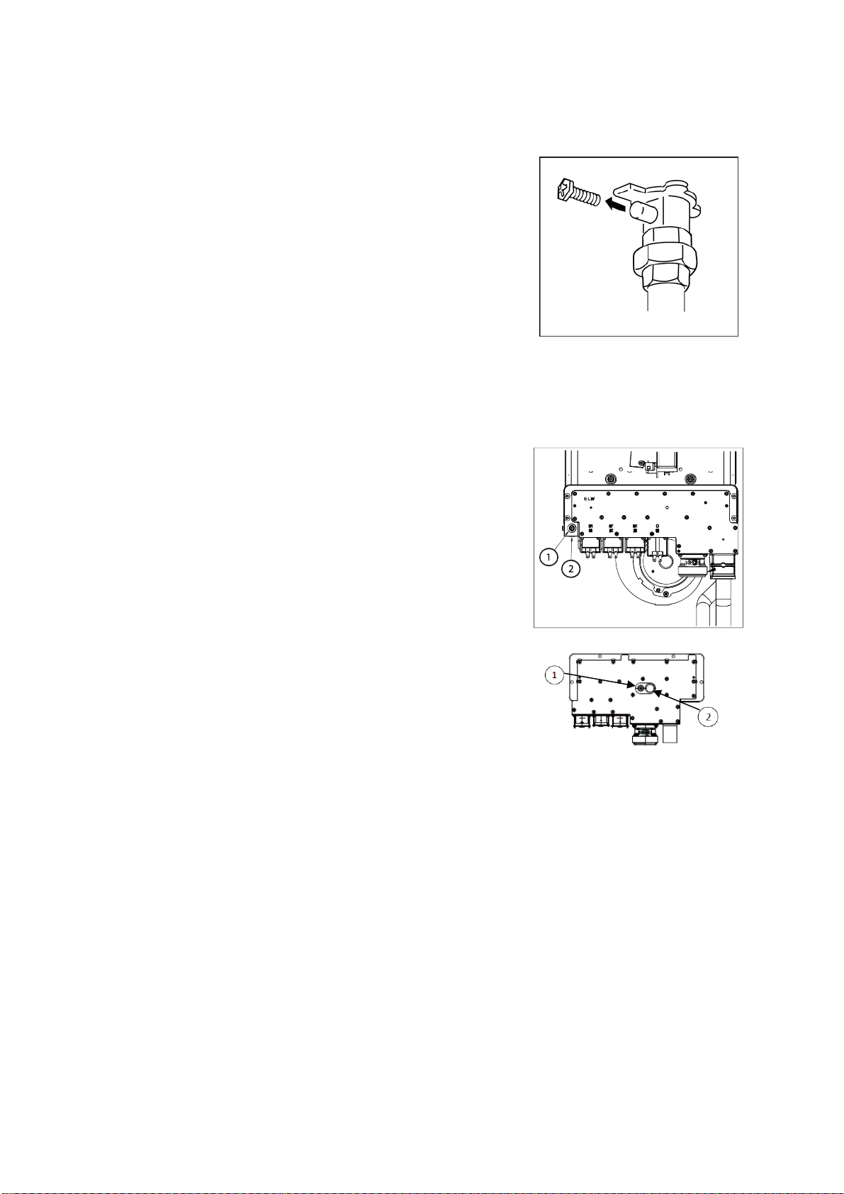
continuously,locatetheManifoldadjustmentbuttons
onthecircuitboardlocatedintherightsideoftheunit
(Figure9).
11) Pressandholdthemaximumpressuresetbutton.
Verifyfromthebelowtablethattheappropriate
pressureisreadfromthemanometer.Ifthepressure
needsadjustment,usetheManifoldpressureincrease
anddecreasebuttonstoadjusttothecorrectpressure,
whilecontinuingtoholddownthemaximumpressure
setbutton.
12) Pressandholdtheminimumpressuresetbutton.
Verifyfromthetablesbelowthattheappropriate
pressureisreadfromthemanometer.Ifthepressure
needsadjustment,usetheManifoldpressureincrease
anddecreasebuttonstoadjusttothecorrectpressure,
whilecontinuingtoholddowntheminimumpressure
setbutton.
ManifoldGasPressureMaximumandMinimumValues
SettingListforManifoldPressuresNR83DVC(GQ‐2457WS‐FFAUS)
SettinglistforGasManifoldpressure(NR83‐DVC)
ManifoldPressureforNR83‐DVC(inchH2O)Coveroff
Dip7=OFFDip8=OFFDip7=ONDip8=OFFDip7=OFFDip8=ONDip7=ONDip8=ON
Ventlengthadjustment
MinimumLengthShortLengthLongLengthMaximumLength
NoVenting
Gastype/VentlengthMax.valueMin.valueMax.valueMin.valueMax.valueMin.valueMax.valueMin.valueMax.valueMin.value
NG/Minlength2.571.002.531.002.490.962.490.96
(Verticaltermination)*(2.53)(0.97)(2.46)(0.95)(2.46)(0.95)(2.40)(0.93)
NG/Maxlength2.531.002.490.962.490.962.490.96
(Verticaltermination)*(2.46)(0.95)(2.46)(0.95)(2.40)(0.93)(2.36)(0.92)
2.651.04
LP/Minlength3.731.363.651.363.611.323.571.32
(Verticaltermination)*(3.61)(1.30)(3.53)(1.30)(3.53)(1.30)(3.49)(1.28)
LP/Maxlength3.651.363.611.323.571.323.571.32
(Verticaltermination)*(3.53)(1.30)(3.53)(1.30)(3.49)(1.28)(3.45)(1.28)
3.81
1.41
*Usethesesettingswhentheunitterminatesusingtheverticalraincap
ManifoldPressure(inchH2O)CoverOff
ModelNameGasTypeSupplyPressure
(inchH2O)MaxValueMinValue
NG 7.93.460.87N‐0931M/NR111‐SV,
N‐0931M‐ASME/NC250‐SV‐ASMELP11.03.650.94
NG7.93.150.75
N‐0931M‐OD/NR111‐ODLP11.04.370.98
NG 7.93.450.94N‐0931M‐DV/NR111‐DV,
N‐0931M‐DV‐ASME/NC250‐DV‐ASMELP11.04.020.91
NG7.92.851.00
NR83OD(GQ‐2457WSUS)LP11.04.251.40
NG7.9NR83‐DVC/NR83DVC(GQ‐2457WS‐
FFAUS)LP11.0
Refertothe“SettinglistforgasManifoldpressure
(GQ‐2457WS‐FFAUSandNR83‐DVC)”below
ManifoldPressure(inchH2O)Coveroff
Dip7=OFFDip8=OFFDip7=ONDip8=OFFDip7=OFFDip8=ONDip7=ONDip8=ONVentlength
adjustmentMinimumShortLongMaximum
GastypeMax.valueMinvalueMax.valueMinvalueMax.valueMinvalueMax.valueMinvalue
NG2.750.902.700.852.700.852.650.80
LP3.851.253.801.253.751.203.701.20
FIGURE9

11
13) AftertheManifoldpressureshavebeen
confirmed,verifythattheflameisasteadyblue
colorusingtheinspectionwindow(Figure10).
14) Turnoffwaterandgastounit.Attachscrew
toManifoldtapandturnongassupplytothe
unit.
15) Performafinalgasleakcheckaroundthe
entireManifoldPlate,especiallyneartheGas
PipeandManifoldinlet,usingagasleak
detectiondevice.
16) IftheRemoteControllerneedstoberemoved,
disconnectelectricalpowertoheaterand
proceedtoremovecontrollerconnections.
FIGURE10

12
Applyconversionlabels:
1) ClosetheFrontCoveroftheunitwith4screwspreviouslyremoved.
2) Locatethe2conversionstickersinEnglishsuppliedintheconversionkit.*Forunits
certifiedforuseinCanadalocatethe2conversionstickersinFrench.
3) PlacethestickerindicatingthenewinletandManifoldpressuresdirectlyabovethe
ratingstickersoasnottocoveranyexistingmarkingsasindicatedby“A”inFigure11.
*ForunitscertifiedforuseinCanadaplaceFrenchstickerwithnewpressuresnextto
Englishsticker.
4) Fillouttherequiredinformationontheremainingstickerindicatingthedate,gastype,
kitnumber,andnameofthecompanyperformingtheconversion.Placethisstickeron
thefrontcoverasindicatedby“B”inFigure11.Donottocoveranyexistingmarkings.
*ForunitscertifiedforuseinCanadaplaceFrenchstickerwithagencyinformation
nexttoEnglishsticker.
(N‐0931M/NR111‐SV&ASMEModel)(N‐0931M‐DV/NR111‐DV&ASMEModel)(N‐0931M‐OD/NR111‐OD)
FIGURE11
NR83‐DVC
NR83DVC(GQ‐2457WS‐FFAUS)
NR83OD(G
Q
‐2457WSUS)

13
InstallationChecklist:
PartsReplacement:
□RemoveexistingManifoldPlate,BurnerDamperandO‐rings.Discardtheseparts.
□ReplacewithnewManifoldPlate,BurnerDamperandO‐rings.
□MakesurethatManifoldPlateandO‐ringsaresecuredproperlyinplace.
Adjustments:
□AccessMaintenanceWritermodeandsettheA1itemnumbertodesiredgastype.
□Confirmgastypesettings.
Testing:
□Beforeopeninggasvalvetotheunit,verifythegassupplypressureiswithinoperating
rangeoftheuint.
□Ifgassupplypressureisnotwithinspecification,adjustthepressureattheregulatoror
installasecondaryregulatoronthesupplylineconnectedtotheunit.
□RemovehexPhilipsscrewfrominletoftheunitandconfirmgassupplypressurewith
manometer.Replacescrewafterconfirmationofgassupplypressure.
□RemovehexPhilipsscrewor1/8”NPTscrewfromgasvalveandconnectmanometerto
GasValve.
□CheckforgasleaksaroundgasinletfittingandManifoldPlateusingagasleakage
detector.
□CheckandconfirmcorrectManifoldpressures.Makeadjustmentifnecessary.Replace
screwafterManifoldpressureshavebeenconfirmed.
□Performfinalgasleakcheckagainwithgasleakagedetector.
ApplyConversionLabels:
□PlaceNewInletandManifoldPressureRatingStickeraboveratingstickeronfrontcover.
□FilloutinformationonDate,GasType,KitNumber,NameofCompanyStickerandplace
onfrontcover.
□IncludeFrenchstickersforunitscertifiedforuseinCanada.
This manual suits for next models
7
Table of contents
Other Noritz Industrial Equipment manuals