TESTING RA 100 Concrete User manual

TESTING Bluhm & Feuerherdt GmbH
Manufacture and sale of equipment
for the testing of construction material
Motzener Str. 26b
DE - 12277 Berlin
Tel. +49(0)30/710 96 45-0
Fax +49(0)30/710 96 45-98
www.testing.de
1
Operating Manual
RA 100 Concrete,
non-destructive, quick determination of compressive strength
and modulus of elasticity on samples
of cement, mortar and concrete
Model 1.0390

RA 100 Concrete
Model 1.0390
2
Importance of this Operating Manual:
We expect and require that the User reads, understands and observes all parts of this Operating
Manual.
Contents: Page no.:
1.!Safety instructions ................................................................................................... 3!
2.!Scope of delivery .................................................................................................... 4!
3.!Start-up ................................................................................................................... 5!
4.!Software .................................................................................................................... 7!
4.1. Tab „Measurement“ ................................................................................................ 7!
4.2. Tab „Archive“ ........................................................................................................ 11!
4.3. Tab „Settings“ ........................................................................................................ 12!
4.4. Tab “Concrete Types” ........................................................................................... 14!
5.!Troubleshooting ..................................................................................................... 15!

RA 100 Concrete
Model 1.0390
3
1. Safety instructions
Application
Product for commercial use only!
Product exclusively for intended use with building material samples!
Safety
Do not interfere or modify our products. Never open the device. Otherwise any warranty /
conformity expires.
Operating temperatures
Microphone: -10 ÆC to +85 ÆC
Tablet: +10 ÆC to +40 ÆC
If you have any questions, please contact us:

RA 100 Concrete
Model 1.0390
4
2. Scope of delivery
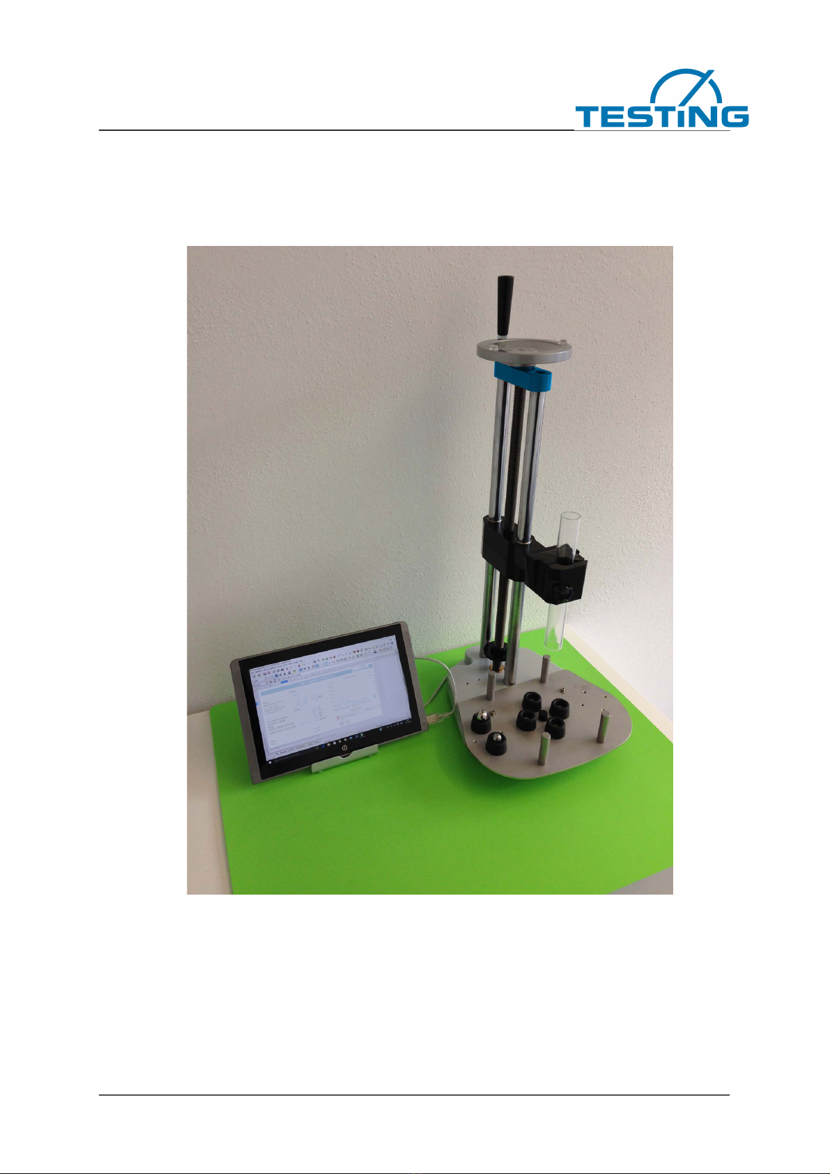
The scope of delivery of the product RA 100 Concrete includes the following parts:
• 1 test stand with integrated USB microphone and 1.8 m USB cable
• 1 tablet, 10", 32 GB, Windows 10
• Pre-installed RA 100 Concrete Software
• 1 stainless steel base plate
• 6 screwable vibration absorbers
• 4 steel balls (2x 20 mm Ø, 2x 14 mm Ø)
• 1 acrylic downpipe
• 1 height-adjustable sample holder
• 1 adjustable tablet holder
• 1 Bluetooth keyboard
• 1 Bluetooth mouse
RA 100 Concrete
Model 1.0390
5
3. Start-up
For easy and uncomplicated starting the following steps are recommended:
1. Place the RA 100 Concrete test stand firmly on a fat surface
2. Assemble base plate
3. Screw in vibration absorbers
4. Set up the test specimen
RA 100 Concrete
Model 1.0390
6
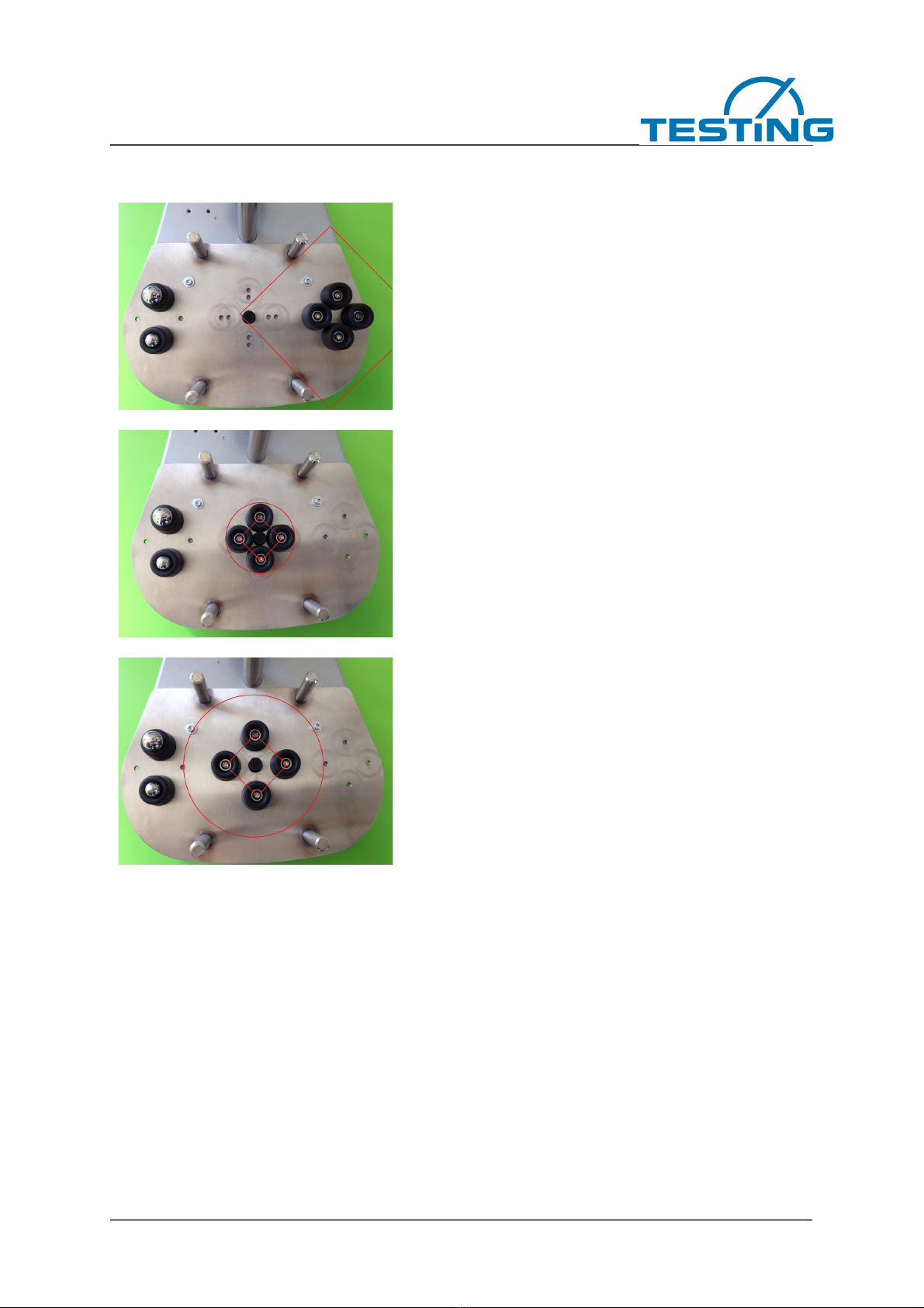
(Position recommendation marked in red)
Recommended sample position of a cube
sample 150mm/150mm/150mm
Recommended frequency range (cube):
3500 Hz - 9500 Hz
Stable sample position for cylinder samples
with small diameter and prism samples with
small width
Recommended frequency range (prism):
10000 Hz - 16000 Hz
Optimum sample position for cylindrical
samples with larger diameters and prism
samples with larger widths
Recommended frequency range (cylinder):
3000 Hz - 9000 Hz
Smaller specimens such as 40 x 40 x 160 mm prisms and smaller drill specimens can be
clamped centrally in the supplied multi-purpose clamp.
5. Fasten the acrylic downpipe in the holder with the M8 screw
6. Start Tablet and connect the USB adapter to the tablet
7. Start the program Resonance Analysis and make basic settings (see Chapter 4 –
Software)
8. Start Measurement

RA 100 Concrete
Model 1.0390
7
Make sure that USB PnP Sound Device is selected as the default device in the Windows settings
for the recording device.
AGC" must be deactivated under "Properties - User-defined" and a level of 100 must be set
under "Level".
4. Software
The device measures the natural resonances of test specimens by means of a steel ball impact
and microphone. The sound vibrations are digitized and evaluated spectrally. Vibrations are
selected and evaluated which allow analytically simple conclusions to be drawn about the elastic
material values. Based on empirical insights, compressive strength values are also estimated
from the elasticity values for concrete.
4.1. Tab „Measurement“
Entries
In this area the settings are entered in advance of the measurement process.
Description
Name of the measuring process / the sample - free text.
Concrete type, Grain, Fly ash
In the first input cell, the sort description of a concrete can be entered with which properties
stored from the sort table (own spreadsheet of the calculation program) can be called up, of
which - if available - the characteristic cube strength value, the maximum grain size and the fly
ash content are displayed.

RA 100 Concrete
Model 1.0390
8
The fck-cube compressive strength value is used for the target display (first column next to the
diagram) for comparison with the measurement. The maximum grain display is not used directly,
it indirectly influences an otherwise determined calibration correction factor, which is listed in the
last column of the sort list and corrects the determination of compressive strength according to
empirical experience.
x y/d z
Describes the sample shape for calculating the velocity of sound from the resonant frequency
and is used to calculate the sample volume required for density calculation if the sample weight
is entered.
x and y/d describe the base area, z the sample height. If x = 0, x/d input means the diameter of a
cylinder, if x is entered a value, x/d means the second side of a base area rectangle (the sample
then corresponds to a rectangular or square prism, or even a cube).
Example:
300mm standard cylinder
x = blank
y/d = 150
z = 300
160mm standard prism
x = 40
y/d = 40
z = 160
150mm standard cube
x = 150
y/d = 150
z = 150
Weight. De.calc. De.man.
If a weight is entered in the first input cell, the program determines the density with the calculated
volume. If the weight is 0, a density value must be entered manually in the rear input cell or the
value there is taken.
Frequency from to
Here are the frequencies that can be changed at any time (also after the measurement) and
between which a resonance is sought. This area is also used for the adjacent graphic.
Recommendations for common sample shapes:
150mm cube sample: 3500 Hz - 9500 Hz
300mm cylinder sample: 3000 Hz - 9000 Hz
160mm prism sample: 10000 Hz - 16000 Hz
These settings cover the most common varieties.
For very soft or very hard samples the frequency window must be shifted up or down.
RA 100 Concrete
Model 1.0390
9
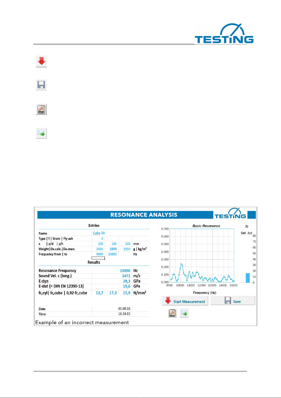
Start measurement
When this button is pressed, the microphone goes into standby mode and waits for
the pulse that triggers the measurement process
Save
If this button is pressed, the current measurement is stored in the archive
Export as PDF
With this function, the measurement can be exported as a PDF report
Send as e-mail
After completion of the measurement, the measurement data can also be sent as an
e-mail to a stored e-mail address
Results
After the measurement process, the result values are displayed in this area. The isolated reso-
nance frequency of the sample and the value of the compressive strength are shown graphically
on the right in a target-actual diagram. The target value of the compressive strength is either
entered manually or taken from the corresponding sort list.
Incorrect measurements due to premature triggering, incorrect sample storage or other
interference can be identified directly on an uneven frequency image.

RA 100 Concrete
Model 1.0390
10
Resonant Frequency
This is the actual and most important measured value.
In the set frequency range, the signal frequency response recorded by the microphone is deter-
mined in the manner of a digital short-term Fourier transformation and also displayed graphically.
A resonance curve expected in the set frequency range is visible and evaluated with regard to its
maximum position in the frequency range and the resonance frequency is used to determine the
corresponding elastic material constants.
Velocity of sound
The pure material constant sound velocity is determined from the resonant frequency and sam-
ple dimensions.
Solids have different types of sound wave propagation, each with its own speed. In an isotropic
solid such as concrete (uniform behaviour in all directions) there are two types of waves in the
unlimited medium, which propagate at different speeds and are described by two independent
elastic constants. These waves are generally detected by ultrasound, since the larger dimen-
sions of the specimens do not play a role in the small wavelengths and the transit time measure-
ments.
In resonance measurements, the interfaces with their abrupt elastic property changes come into
play and complicate sound propagation, according to the sample dimensions. Sound propagation
is simplest measured in long bars where the transverse dimensions are small compared to the
wavelengths. For the velocity of sound determined by longitudinal oscillation resonance the
following applies:
c-shaft = radical (E/den)
and therefore: E = den*c2 (E = Young's modulus and den = density)
In this table result cell, c always means shaft speed. Other measured velocities, including
torsional wave velocities, are converted by means of relationships between elastic constants and
consideration of the specimen shape.
If the transverse contraction coefficient must be used, the mean value 0.2 valid for concrete is
used. The possibility of variation of 0.14...0.26 for concrete has little effect on the result.
Due to the cube specimen shape, which is widely used in the concrete industry, not a longitudi-
nal oscillation shape but the isolated lowest torsional oscillation was selected for reliable detec-
tion, which is converted into a comparable longitudinal speed of sound. The cube basic frequen-
cies are described in:
Harold H. Demarest, Jr. The journal of the Acoustical Society of America Volume 49 Number3
(Part 2) 1971, Cube-Resonance Method to Determine the Elastic Constants of Solids
E-dyn
The dynamic modulus of elasticity is a pure material property, not dependent on specimen geom-
etry and measuring conditions. For concretes, it is largely identical to the modulus of origin of the
stress-strain curve.

RA 100 Concrete
Model 1.0390
11
E-stat DIN EN 12390-13
The static modulus of elasticity is estimated from the dynamic modulus of elasticity according to
theoretical models, similar comparison measurements from literature and own
measurements.
Fc-cyl fc-cube 0,92 fc-cube
The result values correspond to a conversion of the measured sound velocity according to
empirical values obtained in test series with several hundred cube compressive strength values
produced in the ready-mixed concrete product monitoring. For standard concrete, the standard
curve, which can be adjusted with correction factors, corresponds to a dependence of the modu-
lus of elasticity on compressive strength with a power of approx. 0.3, i.e. E proportional fc high
0.3, which is usually preferred in the literature.
The dependence on density implied in E-dyn is not considered in standard concrete, fc is thus
calculated directly from the speed of sound. However, in the case of lightweight concrete, a
smaller power number is used for the compressive strength dependence: The central calibration
curve is designed for the cube strength in the cell fc-cube, the cylinder strength for a
150mm/300mm cylinder is calculated back into the cell fc-cyl. The dry cube storage for the
28-day value with that is taken into account for standard concrete with the factor 0.92 in the cell
0.92 fc-cube.
4.2. Tab „Archive“
On the basis of the measurement processes stored in the archive, it can be precisely traced at
any time under which pre-setting’s, measurement conditions and at which time which character-
istic properties of the test specimens existed.
With the button >Erase archive< the measuring processes are deleted.
In the "Settings" tab, you can define the selection and sequence of the data fields displayed.

RA 100 Concrete
Model 1.0390
12
4.3. Tab „Settings“
The values entered represent the basic software settings.
Recording
Sampling rate:
Sampling rate of the audio recording
Recording time:
Length of the recording
Trigger limit:
Level at which the recording is triggered
Trigger minimum duration:
Time period for which the level must be increased in order to trigger a measurement
Maximum waiting time:
Waiting time for trigger - if the measurement is not triggered, the software returns to the normal
state

RA 100 Concrete
Model 1.0390
13
Changes to these settings can strongly influence the quality of the measurement.
Please contact us if you have any questions:
Audio device
Selecting the recording and playback device. (Not necessary from Windows 8.1)
View
Optionally, the screen can be switched to full screen mode using the
> Switch Screen button <
When changing the setting with the number 1, the program is displayed in full screen mode at
each start.
The desired maximum Y value can be entered for scaling the Y-axis of the "basic resonance"
diagram. If the value is "0", the diagram is automatically scaled.
Archive
Here you can select the cells that are to be stored in the archive after saving.
E-Mail
The addresses of the desired recipients can be entered here (separate multiple entries with com-
mas). In addition, the subject line of the e-mail can be pre-set. The evaluation data to be sent
can be supplemented or reduced in the "E-Mail Text" area by entering the table fields.
Licensing
License number for using the software
RA 100 Concrete
Model 1.0390
14
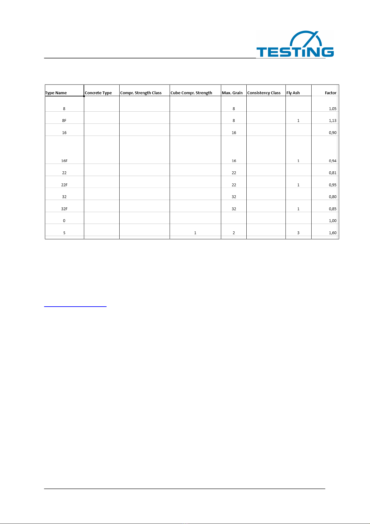
4.4. Tab “Concrete Types”
Exemplary excerpt from a stored list of varieties
If a variety list of types is stored, additional details can be used for the display and calculation.
If you have any questions, please contact us:

RA 100 Concrete
Model 1.0390
15
5. Troubleshooting
Issue:
As soon as you click on "Start measurement" - the software immediately jumps to "process".
Solution:
USB microphone of the test stand not connected.
OR
Correct the trigger limit upwards in the "Settings" tab.
Issue:
The software does not start processing after the ball is dropped.
Solution:
Correct the trigger limit downwards in the "Settings" tab.
If you have any questions, please contact us:
This manual suits for next models
1
Table of contents
Other TESTING Test Equipment manuals


