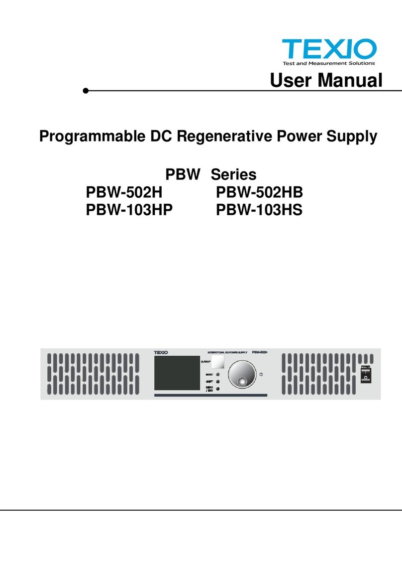
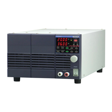
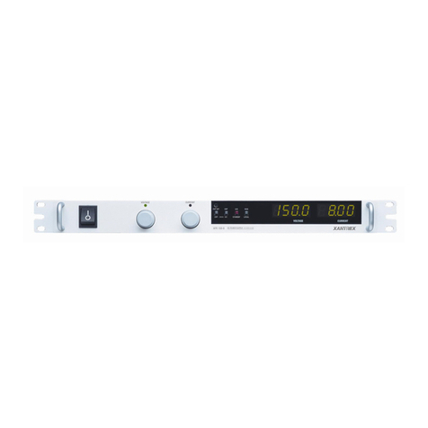
TEXIO PS-A Series User manual

INSTRUCTION MANUAL
REGULATED DC POWER SUPPLY
PS-A SERIES
PS6-66A PS6-133A
PS10-40A PS10-80A PS10-120A
PS20-20A PS20-40A PS20-60A
PS40-10A PS40-20A PS40-30A
PS60-6.6A PS60-13.3A PS60-20A
OPTIONAL INTERFACE UNITS FOR
PS-A SERIES
IF-71RS IF-70GU IF-70PS
B71-0024-30

■ About Brands and Trademarks
The company and product names described in this manual are the brands and trademarks owned by the respective
companies or organizations in each country and region
■ About the Instruction Manual
Permission from the copyright holder is needed to reprint the contents of this manual, in whole or in part. Be aware that
the product specifications and the contents of this manual are subject to change for the purpose of improvement.

CONTENTS
USING THE PRODUCT SAFETY ............................................................................................................... Ⅰ-Ⅲ
1. PS-A SERIES_________________________________________________________ 1
1-1. About This Manual.........................................................................................................................1
1-2. Outline of Product..........................................................................................................................1
1-3. Features ........................................................................................................................................1
1-3-1. PS-A Power Supply Unit .........................................................................................................1
1-3-2. IF-71RS (option) .....................................................................................................................2
1-3-3. IF-70GU(option).....................................................................................................................2
1-3-4. IF-70PS(option).....................................................................................................................2
1-3-5. Cable for master-slave operation (option) ...............................................................................2
1-3-6. Handle (option) .......................................................................................................................2
2. Prior to Use__________________________________________________________ 3
2-1. Accessories ...................................................................................................................................3
2-2. Connecting the power cable ..........................................................................................................4
2-3. Connecting to the output terminals ................................................................................................5
2-3-1. Attaching the output grounding cable......................................................................................5
2-3-2. Connecting the voltage remote sensing cables.......................................................................5
2-3-3. Attaching the rear output terminal cover .................................................................................6
2-4. Caution on Connecting to a Capacitive Load.................................................................................6
2-5. Connecting the protective grounding terminal on the bottom face.................................................6
2-6. Caution on mounting the unit in a rack ..........................................................................................7
2-7. Connecting the Power Cable to the Primary Power.......................................................................7
2-8. Installation Environments...............................................................................................................7
3. Panels ______________________________________________________________ 8
3-1. Front Panel ....................................................................................................................................8
3-2. Operation Panel.............................................................................................................................9
3-3. Rear Panel...................................................................................................................................12
4 GENERAL INSTRUCTIONS_____________________________________________ 15
4-1. Connecting loads .........................................................................................................................15
4-2. Alarm ...........................................................................................................................................16
5 FUNCTIONS AND OPERATION PROCEDURES ____________________________ 17
5-1. Operation modes .........................................................................................................................17
5-2. Turning On Power........................................................................................................................17
5-2-1. Display when power is turned on ..........................................................................................17
5-2-2. Recalling Settings When Turning on Power, and Saving the Setting Data............................18
5-3. Basic Operation ...........................................................................................................................19
5-3-1. Voltage setting procedure .....................................................................................................19

5-3-2. Current setting procedure .....................................................................................................19
5-3-3. Fine adjustment of voltage/current........................................................................................19
5-4. Output Functions .........................................................................................................................20
5-5. Memory Function.........................................................................................................................21
5-5-1. Storing and recalling preset voltage/current data......................................................................21
5-6. Switching the display in the Voltage/Current Indicator Display. ........................................................22
5-6-1. Switching between the set voltage/current display and output voltage/current display .........22
5-6-2. Displaying Power in the Voltage and Current Indicators .......................................................23
5-7. Protective Functions ....................................................................................................................25
5-7-1. Display when protective functions are activated ...................................................................25
5-7-2. Modification of the Set Values of Protective Functions .........................................................25
5-7-3. Deactivating Protective Functions ...........................................................................................26
5-8. Key Lock / Local Function............................................................................................................27
5-8-1. Key lock and unlock procedures..............................................................................................27
5-8-2. Remote mode deactivation procedure ..................................................................................27
6 SETTING WITH THE MENU KEY ________________________________________ 28
6-1. Output HI-R Function...................................................................................................................29
6-1-1. Setting the output HI-R function............................................................................................29
6-1-2. Output on/off operation while output HI-R function is activated.............................................30
6-2. Outout Off Timer ..........................................................................................................................31
6-2-1. Setting the output off timer .....................................................................................................31
6-2-2. Operating the output off timer..................................................................................................32
6-3. Specifying the automatic cancellation time of the setting menu display............................................33
6-4. Specifying Settings when the Power Is Turned On ......................................................................34
6-4-1. Recalling preset values when the power is turned on...............................................................34
6-4-2. Setting the output when the power is turned on .......................................................................35
6-4-3. Setting the CC priority mode ...................................................................................................36
6-4-4. Setting the display while the output is off.................................................................................39
6-5. Clearing the Memory ...................................................................................................................40
7 MASTER-SLAVE OPERATION __________________________________________ 43
7-1. Configuration of Master and Slave Units .....................................................................................43
7-1-1. Configuring the master and slave units.................................................................................43
7-1-2. Specifying the number of units..............................................................................................45
7-2. Parallel Master-Slave Operation..................................................................................................47
7-3. Serial Master-Slave Operation.....................................................................................................48
8 SEQUENCE OPERATION ______________________________________________ 49
8-1. Setting of Sequence Operation....................................................................................................49
8-1-1. Turning on the power switch with sequence operation..........................................................49
8-1-2. Setting the unit to start in sequence operation by turning the power switch on...................49
8-2. Sequence Programs ....................................................................................................................51
8-2-1. Step No. and setting items ....................................................................................................51

8-2-2. Setting step execution...........................................................................................................51
8-3. Confirming the Step No. and the Step Being Executed ...............................................................52
8-3-1. Confirming the step No. while the sequence program is stopped .........................................52
8-3-2. Confirming the step No. being executed during sequence program execution .....................52
8-4. Confirming the Setting Items for Steps ........................................................................................53
8-5. Confirming the settings for sequence program execution............................................................54
8-6. Executing Sequence Programs ...................................................................................................55
8-6-1. Automatic execution of sequence programs .........................................................................55
8-6-2. Paused and resumed sequence programs ...........................................................................56
8-6-3. Manual execution of sequence programs .............................................................................57
8-6-4. Stopping sequence programs ...............................................................................................59
9 OPERATION BY EXTERNAL ANALOG SIGNAL ____________________________ 60
9-1. Analog Interface Boards ..............................................................................................................60
9-1-1. Cautions on applying analog IF boards.................................................................................60
9-1-2. Wiring an analog signal to the standard board......................................................................61
9-1-3. Wiring an analog signal to IF-70PS.......................................................................................63
9-2. Operating the Analog IF Board ....................................................................................................65
9-2-1. Setting the Voltage................................................................................................................65
9-2-2. Adjusting the set voltage .......................................................................................................67
9-2-3. Current setting ......................................................................................................................68
9-2-4. Adjusting the set current .......................................................................................................70
9-2-5. Turning the output on/off through external contacts ..............................................................71
9-2-6. Checking the status when the output is off............................................................................73
9-2-7. Main relay ON/OFF operation ...............................................................................................73
10 INTERFACE OPTION _________________________________________________ 74
10-1. Accessories ...............................................................................................................................74
11 USING DIGITAL COMMUNICATION INTERFACE FOR REMOTE CONTROL_____ 75
11-1. Outline .......................................................................................................................................75
11-1-1. IF-70GU ...............................................................................................................................75
11-1-2. IF-71RS................................................................................................................................76
11-1-3. Cable and connector settings ................................................................................................77
11-1-4. Address settings ...................................................................................................................78
11-1-5. GP-IB connection..................................................................................................................79
11-1-6. USB connection....................................................................................................................79
11-1-7. RS-232C connection.............................................................................................................80
11-1-8. Local bus connection ............................................................................................................81
11-1-9. When used as a PSR or PSR-M supply unit ..........................................................................81
11-2. Communication Control Commands ..........................................................................................82
11-2-1. Communication commands table...........................................................................................82
11-2-2. Automatic message output ....................................................................................................83
11-2-3. Command format ..................................................................................................................83

11-3. Commands.................................................................................................................................85
11-3-1. Voltage setting (VOLT) .........................................................................................................85
11-3-2. Current setting (AMP) ...........................................................................................................85
11-3-3. OVP setting (OVP)................................................................................................................85
11-3-4. UVP setting (UVP) ................................................................................................................85
11-3-5. OCP setting (OCP) ...............................................................................................................85
11-3-6. Output setting (OUTPUT)......................................................................................................86
11-3-7. Status query (XSTATUS) .......................................................................................................86
11-3-8. Recalling preset settings (PRESET) ......................................................................................86
11-3-9. Saving preset settings (SETPRE)..........................................................................................86
11-3-10. Preset voltage setting (PREVOLT).......................................................................................87
11-3-11. Preset current setting (PREAMP).........................................................................................87
11-3-12. Power monitor display setting (MONDSP)............................................................................87
11-3-13. Power-off display setting (DSPY).........................................................................................87
11-3-14. Monitor display switching (CHECK) .....................................................................................88
11-3-15. CC priority mode setting when the output is turned on (CCPRIO) .........................................88
11-3-16. Output HI-R setting (HIR) ....................................................................................................88
11-3-17. Output off timer setting (OFFTM) .........................................................................................88
11-3-18. Automatic cancellation time setting for the setting menu display (ESC) .................................88
11-3-19. Main relay setting (POWER)................................................................................................89
11-3-20. Unlocking (GTL)..................................................................................................................89
11-3-21. Local lock out setting (LLO) ................................................................................................89
11-3-22. Sequence operation setting when the power is turned on (PONSEQ)...................................89
11-3-23. Preset setting when the power is turned on (PONPRE)........................................................89
11-3-24. Output setting when the power is turned on (PONOUT) .......................................................90
11-3-25. Main relay setting when the power is turned on (PONPOW).................................................90
11-3-26. Notification setting 1 (MASK)...............................................................................................90
11-3-27. Notification setting 2 (AMASK).............................................................................................91
11-3-28. Notification setting 3 (SMASK).............................................................................................91
11-3-29. Querying alarm status (ALM)...............................................................................................91
11-3-30. Alarm reset (EXIT_ALM) .....................................................................................................91
11-3-31. Clearing sequence programs (SCLR) ..................................................................................91
11-3-32. Writing sequence program (XSWRITE)................................................................................92
11-3-33. Reading out a sequence program (XSREAD) ......................................................................93
11-3-34. Sequence start point setting (SSADR) .................................................................................93
11-3-35. Sequence end point setting (SEADR) ..................................................................................93
11-3-36. Sequence execution mode setting (SMODE) .......................................................................94
11-3-37. Sequence repeat cycle setting (SCYCLE)............................................................................94
11-3-38. Sequence mode setting (CHGSEQ) ....................................................................................94
11-3-39. Panel operation mode setting (CHGNORM).........................................................................94
11-3-40. Sequence start (SSTART) ...................................................................................................94

11-3-41. Sequence stop (SSTOP).....................................................................................................94
11-3-42. Sequence pause (SPAUSE)................................................................................................95
11-3-43. Sequence jump (SSTEP) ....................................................................................................95
11-3-44. Reading out the sequence execution status (SRUN) ........................................................95
11-3-45. Reset (*RST) ......................................................................................................................95
11-3-46. Function reset (RESET) ......................................................................................................95
11-3-47. Reading out the status byte (*STB)......................................................................................96
11-3-48. Reading out the product information (*IDN)..........................................................................96
11-3-49. Querying the model and specifications (MODEL) .................................................................96
11-3-50. Local bus setting (ADRS) ....................................................................................................97
11-4. Cautions about communication..................................................................................................98
11-5. Communication Specifications ...................................................................................................98
11-6. Setting Range Tables ...............................................................................................................100
Appendix A. TROUBLE SHOOTING ______________________________________ 101
Appendix B. OUTSIDE DIMENSIONS _____________________________________ 103
Appendix C. SPECIFICATIONS __________________________________________ 104

I
USING THE PRODUCT SAFELY
■Preface
To use the product safely, read instruction manual to the end.
Before using this product, understand how to correctly use it.
If you read the manuals but you do not understand how to use it, ask us or your local dealer.
After you read the manuals, save it so that you can read it anytime as required.
■ Pictorial indication
The manuals and product show the warning and caution items required to safely use the product.
The following pictorial i ation and warning character indication are provided. ndic
<Pictorial indication>
Some part of this product or the manuals may show this pictorial indication.
In this case, if the product is incorrectly used in that part, a serious danger may be brought
about on the user's body or the product.
To use the part with this pictorial indication, be sure to refer to the manuals.
If you use the product, ignoring this indication, you may get killed or seriously injured.
This indication shows that the warning item to avoid the danger is provided.
If you incorrectly use the product, ignoring this indication, you may get slightly injured or
the product may be damaged.
This indication shows that the caution item to avoid the danger is provided.
Please be informed that we are not responsible for any damages to the user or to the third person, arising from
malfunctions or other failures due to wrong use of the product or incorrect operation, except such responsibility for
damages as required by law.

II
USING THE PRODUCT SAFELY
■Do not remove the product's covers and panels
Never remove the product's covers and panels for any purpose.
Otherwise, the user's electric shock or fire may be incurred.
■Warning on using the product
Warning items given below are to avoid danger to user's body and life and avoid the damage or deterioration of the
product. Use the product, observing the following warning and caution items.
■Warning items on power supply
●Power supply voltage
The rated power supply voltages of the product are 100, 120, 220 and 240VAC. The rated power supply voltage for
each product should be confirmed by reading the label attached on the back of the product or by the “rated” column
shown in the instruction manual. The specification of power cord attached to the products is rated to 125VAC for
all products which are designed to be used in the areas where commercial power supply voltage is not higher
than 125VAC. Accordingly, you must change the power cord if you want to use the product at the power supply
voltage higher than 125VAC. If you use the product without changing power cord to 250VAC rated one, electric
shock or fire may be caused. When you used the product equipped with power supply voltage switching system,
lease refer to the corresponding chapter in the instruction manuals of each product.p
●Power cord
(IMPORTANT) The attached power cord set can be used for this device only.
If the attached power cord is damaged, stop using the product and call us or your local dealer.
I
f the power cord is used without the damage being removed, an electric shock or fire may be caused.
●Protective fuse
If an input protective fuse is blown, the product does not operate. For a product with external fuse holder, the fuse
may be replaced. As for how to replace the fuse, refer to the corresponding chapter in the instruction manual.
If no fuse replacement procedures are indicated, the user is not permitted to replace it. In such case, keep the
case closed and consult us or your local dealer. If the fuse is incorrectly replaced, a fire may occur.
■Warning item on Grounding
If the product has the GND terminal on the front or rear panel surface, be sure to ground the product to safely use it.
■Warnings on Installation environment
●Operating temperature and humidity
Use the product within the operating temperature indicated in the “rating” temperature column.
If the product is used with the vents of the product blocked or in high ambient temperatures, a fire may occur.
Use the product within the operating humidity indicated in the “rating” humidity column.
Watch out for condensation by a sharp humidity change such as transfer to a room with a different humidity.
Also, do not operate the product with wet hands. Otherwise, an electric shock or fire may occur.
●Use in gas
Use in and around a place where an inflammable or explosive gas or steam is generated or stored may result in an
explosion and fire. Do not operate the product in such an environment.
Also, use in and around a place where a corrosive gas is generated or spreading causes a serious damage to the
product. Do not operate the product in such an environment.
●Installation place
Do not insert metal and inflammable materials into the product from its vent and spill water on it.
Otherwise, electric shock or fire may occur.

III
USING THE PRODUCT SAFELY
■Do not let foreign matter in
Do not insert metal and inflammable materials into the product from its vent and spill water on it.
Otherwise, electric shock or fire may occur.
■Warning item on abnormality while in use
If smoke or fire is generated from the product while in use, stop using the product, turn off the switch, and remove the
power cord plug from the outlet. After confirming that no other devices catch fire, ask us or your local dealer.
■Input / Output terminals
Maximum input to terminal is specified to prevent the product from being damaged.
Do not supply input, exceeding the specifications that are indicated in the "Rating" column in the instruction manual of
the product. Also, do not supply power to the output terminals from the outside.
Otherwise, a product failure is caused.
■Calibration
Although the performance and specifications of the product are checked under strict quality control during shipment
from the factory, they may be deviated more or less by deterioration of parts due to their aging or others.
It is recommended to periodically calibrate the product so that it is used with its performance and specifications stable.
For consultation about the product calibration, ask us or your local dealer.
■Daily Maintenance
When you clean off the dirt of the product covers, panels, and knobs, avoid solvents such as thinner and benzene.
Otherwise, the paint may peel off or resin surface may be affected. To wipe off the covers, panels, and knobs, use a
soft cloth with neutral detergent in it.
During cleaning, be careful that water, detergents, or other foreign matters do not get into the product.
If a liquid or metal gets into the product, an electric shock and fire are caused.
During cleaning, remove the power cord plug from the outlet.
Use the product correctly and safely, observing the above warning and caution items.
Because the instruction manual indicates caution items even in individual items, observe those caution items to correctly
use the product.
If you have questions or comments about the manuals, ask us or E-Mail us.

1. PS-A SERIES
1-1. About This Manual
This manual applies to the following PS-A series power supply units and optional interface units.
●PS-A series:
Rated Current
Rated
Voltage 400W 800W 1200W
6V PS6-66A PS6-133A -
10V PS10-40A PS10-80A PS10-120A
20V PS20-20A PS20-40A PS20-60A
40V PS40-10A PS40-20A PS40-30A
60V PS60-6.6A PS60-13.3A PS60-20A
●Optional interface units for the PS-A series
IF-71RS,IF-70GU,IF-70PS
1-2. Outline of Product
The PS-A series are small-sized and lightweight switching type regurated DC power supply units. Because the PS-A
series power supply units are highly reliable and have a variety of protective functions, they are ideally suited for
industrial use, such as for performing reliability tests, durability tests, and the aging of electronic components.
The PS-A series offer a variety of functions for a variety of applications: preset function (3 setting points); protective
functions against output overvoltage, under voltage and overcurrent; output discharge circuit cancel function; output
off timer function; CC priority mode while the output is on; sequence function; and operation by external analog
signal.
There are 2 types of optional interface boards, IF-71RS and IF-70GU. These boards replace the standard board
equipped with the unit and provide communication functions.
1-3. Features
1-3-1. PS-A Power Supply Unit
•Selection of setting digits for voltage and current setting
The output voltage and current are indicated by 4 digits. You can select a digit to set the voltage and the current.
The PS-A power supply unit is also equipped with a fine adjustment function for instances in which more precise
setting capabilities are required.
•Preset function
The unit has a preset memory for 3 setting points in which different voltage and current settings can be stored. This
function enables you to easily change the voltage and current settings.
•Output HI-R function
This function stops the output discharge circuit of the unit while the output is off.
When used as a power unit for charging batteries or for electroplating, this function minimizes battery discharge and
the peeling of plating caused by charge removal while output is off.
•Output off timer function
To prevent battery overcharge etc., this function automatically turns the output off after a preset amount of time has
passed while the output is on.
•CC priority mode
Compared to general switching power supply units, the PS-A power supply unit is better able to reduce current
overshoot, thanks to our original current-overshoot inhibit circuit. This circuit produces a load that enables the unit
to operate at a constant current while the output is on.
•Sequence function
Sequence programs can be written in the unit from a computer via the optional interface board (IF-71RS, IF-70GU).
Sequence programs can be executed by performing panel or computer operations.
You can also perform sequence operations with a maximum of 1000 steps by using a program written by the
computer. The minimum step unit is 50ms.
•Remote sensing function
This function uses the remote sensing terminal to compensate for voltage drop caused by the wires.
11

•Protective functions
The PS-A power supply unit has protective functions against overvoltage, under voltage and overcurrent for the
primary side, and overvoltage, overcurrent, remote sensing terminal open, and internal heat for the secondary side.
The unit is also equipped with OVP (over-voltage protection), UVP (under-voltage protection), and OCP
(over-current protection). The setting values for these protective functions are changeable.
•Master-slave operation
The PS-A power supply unit can perform master-slave operation.
Master-slave operation can be performed at a maximum of 2400W with the same voltage models parallelly connected
(maximum 800W with 6V type models), and with a maximum of two units of the same model serially connected.
•External analog signal operation
When setting the voltage and current by external voltage and resistance, the setting values set externally will be
superimposed on the setting values set on the panel.
The external setting values can be adjusted on the panel.
The output can be turned on and off by entering external terminal.
• Dispersion circuit for rush current prevention
The PS-A power supply unit is able to restrain and minimize the primary side current and voltage distortions caused
by rush current on the primary side at the time the unit is switched on, thanks to the main relay’s on/off operation and
our original dispersion circuit for rush current prevention.
•Power factor correction circuit, as well as voltage and current range for worldwide use
The PS-A power supply unit is equipped with a power factor correction circuit that has a rated output of
approximately 0.99.
It is operable with supply voltages ranging from 100VAC to 240VAC, without changing the settings.
・CE Marked.
1-3-2. IF-71RS (option)
・Units equipped with the IF-71RS can be connected to a computer and controlled by RS-232C.
As an expansion, the IF-71RS can also control 31 PS-A power supply units via a local bus connection.
・Units equipped with the IF-71RS can be substituted and used for our PSR series and
PSR-M series.
1-3-3. IF-70GU(option)
•The IF-70GU is connected to a computer through a GP-IB or USB.
Fourteen units may be connected with a computer through GP-IB, or 32 units may be connected through USB.
•Units connected to the computer can be connected with 31 PS-A power supply units via a local bus connection.
1-3-4. IF-70PS(option)
•IF-70PS is an option unit that enables the PS-A power supply unit to send and receive the same signal as that of the
external input & output of our PS series.
1-3-5. Cable for master-slave operation (option)
•Cable for parallel master-slave
OP-23P3 : Connectable with three PS-A power supply units.
OP-23P6 : Connectable with six PS-A power supply units.
•Cable for in-series master-slave
OP-23S : Connectable with two PS-A power supply units.
When connecting cables, make sure to connect the correct cables.
Connecting the wrong cables may cause product failure.
1-3-6. Handle (option)
•HK-11 : Attachable with 800W and 1200W models.
22

2. Prior to Use
2-1. Accessories
Make sure the accessories are attached correctly. If there are any problems, please contact one of our sales branches.
Accessories vary by model.
<PS-A series power supply unit accessories>
Power cable: 1 pc
<Example> The above figure shows the cable for
400W and 800W models: [E30-5632] (125V model)
400W and 800W models: [E30-5643] (250V model)
1200W model: [E30-5637]
PS-A SERIES
Simple manual: [B70-0024] 1 copy
Rear output terminal cover: [F07-1586] 1 pc
◆See "2-3-3.Attaching the rear output terminal cover "
Ferrite core for power cable: [L92-0310] 1 pc
◆See "2-2. Connecting the power cable"
Output grounding cable: [E38-3353] 1 pc
◆See"2-3-3.Attaching the rear output terminal cover"
Cushion for ferrite core: [G13-0750] 1 pc
◆See"2-2. Connecting the power cable"
Bolt set: [N99-0416] 1 set
(For connect the load cable to the rear output terminals)
◆See "2-3. Connecting to the output terminals"
M3 Small screw washer : [N67-3006-41] 1 set
(For attach the grounding cable to one of the rear
output terminals)
◆See "2-3-1. Attaching the output grounding cable"
M3 Large screw washer : [N66-3008-41] 2 sets
(For attach the rear output terminal cover.)
◆See "2-3-3. Attaching the rear output terminal cover"
M4 Small screw washer : [N67-4008-41] 1 set
(For Connecting the protective grounding terminal on
the bottom face)
◆See "2-5. Connecting the protective grounding
terminal on the bottom face"
※The cushion for ferrite core is not included with products that have a 1200W type power cable [E30-5637].
33

2-2. Connecting the power cable
The power cable should be connected to an AC inlet or an input terminal block. Make sure to use a power cable that
matches the input voltage of the unit. Because the voltage rating of the supplied power cable is 125VAC, you must
use a different cable when a power voltage greater than 125VAC is used.
Make sure to properly connect the power cable. Failure to do so may result in
electric shock or fire.
Using the unit without the AC input terminal cover may result in electric shock or
fire.
Perform this operation before connecting the power cable to an AC outlet or the distribution panel.
●400W and 800W models
Insert the cushion in the ferrite core and attach it to the power cable. Then fully insert the cable into the AC inlet of
the unit.
●1200W models
1. Unfasten the two screws that fix the AC input
terminal block cover of the unit, and then remove
the cover.
2. Unfasten the three screws from the AC input
terminal block.
3. Use the three screws that were just unfastened to
attach the accessory power cable to the AC input
terminal block of the unit, as indicated below in
Figure 2-1. “Connecting the power cable for 1200W
models”.
Tightening torque of screw: 10kgf/cm
Low tightening torque may result in electric shock
or fire.
The wire colors of the power cable are as follows:
G Green or green/yellow
N White or light blue
L Black or brown
4. Use the two screws that were removed from the
AC input terminal block cover to reattach the
cover.
Tightening torque of screw: 5kgf/cm
4
3
5. For the 1200W power cable [E30-5637], only
attach the accessory ferrite core. Do not attach
the cushion.
For the other types of power cables, insert the
cushion in the core, as shown in the figure on the
left, then attach the cushion to the cable.
Fig. 2-1 Connecting the power cable for 1200W models
5
44

2-3. Connecting to the output terminals
Use the supplied bolt set to connect the load cable to the rear output terminals.
Adjust the tightening torque of each bolt to 25 kgf/cm.
Check the connection between the load and the output terminals of the unit. Make sure that the polarity is not
inverted, and that no short circuits have occurred.
Attach a round crimp-style terminal (inner diameter of at least 6.4 mm) to the
load cable.
Insert the bolt into the hole from left side of the output terminal.
From the right side of the output terminal, first attach the load cable (with the
round crimp-style terminal attached), followed by the washer and then the nut.
Finally, secure the bolt.
Fig. 2-2 Connecting the load cable to the rear output terminals
Make sure the voltage of the unit’s output terminals has sufficiently fallen before
touching and operating the load or output terminals. Failure to do so may result in
electric shock.
2-3-1. Attaching the output grounding cable
(You do not need to perform this operation if the output is not to be grounded.)
Use the M3 Small screw and washer to attach the grounding cable to one of the rear output terminals.
Tightening torque of screw: 5kgf/cm.
2-3-2. Connecting the voltage remote sensing cables
You only need to perform this operation if you plan to use the voltage remote sensing function of the unit.
Use the removed M3 screws to attach the voltage remote sensing cables to the voltage remote sensing terminals.
Tightening torque of screw: 5kgf/cm
Carefully store the positive and negative shorting bars and the two M3 screws that were removed.
From the left side of the rear output terminals, attach the grounding cable to the M3 hole
of one of the output terminals.
Attach the grounding cable to either the positive output terminal or the negative output
terminal. Do not attach the cable to both.
If you attach the grounding cable to both the positive and negative output terminals, the
unit output will short circuit.
Remove the M3 screws (4 screws) from the positive and
negative rear output terminals and the positive and negative
voltage remote sensing terminals, and then remove the
positive and negative shorting bars.
Attach the positive and negative voltage remote sensing
cables to the positive and negative voltage remote sensing
terminals.
Attach a round crimp-style terminal (inner diameter of at
least 3.2mm, with the smallest possible outer diameter) to
the voltage remote sensing cables.
55

2-3-3. Attaching the rear output terminal cover
The rear output terminal cover should always be attached even when rear output terminals of the unit are not in use.
Use the M3 Large screw with washer to attach the rear output terminal cover.
Tightening torque of screw: 5kgf/cm.
Run the load cable and the voltage remote sensing cable
through the output terminal cover, and then fix the output
terminal cover to the unit, using the two large screws with
washers.
Fix the output grounding cable to the output grounding
terminal, together with the output terminal cover.
Output
grounding
cable
2-4. Caution on Connecting to a Capacitive Load
To maintain an output voltage of approximately 0 V when the output is off, the unit is equipped with a discharge circuit
for removing the electric charge from the output capacitor.
When the output is off, it takes approximately 1 second for the discharge circuit to remove the electric charge from the
output capacitor when the capacitor is fully charged to its rated voltage.
If a capacitive load, such as a battery or capacitor, is connected to the unit and used, it takes longer to lower the output
voltage when the output is off. If the output is turned off while a capacitive load is connected, be sure to use a
voltmeter to confirm that the voltage has sufficiently fallen before touching the output terminal or the load.
The discharge circuit for the output capacitor does not work if the unit’s output HI-R function is used.
Compared to when the output HI-R function is not used, it takes longer for voltage to fall when a capacitive load is
used.
2-5. Connecting the protective grounding terminal on the bottom face
There is a protective grounding terminal on the bottom face of this unit.
To ensure the safe use of this product, follow the procedure below to connect the protective grounding terminal.
1. Attach the wire (recommened by the manufacturer) for round crimp-style terminals V1.25-M4 (JST) or equivalent.
2. Attach the round crimp-style terminal to the cable.
3. Attach the cable with round crimp-style terminal to the protective grounding terminal on the bottom face of the unit,
using the accessory M4 screw for the grounding connection to secure the cable.
Make sure to properly connect the protective grounding terminal on the bottom face.
Failure to do so may result in electric shock.
If you do not connect the protective grounding terminal on the bottom face, it will
come off from the CE conformity.
66

2-6. Caution on mounting the unit in a rack
When mounting the unit in a rack, use one of the following attachments:
・Rack mount adapter RM-608J (for JIS rack)
•RM-608E (for EIA rack) and rack mount frame attachment RJ-608-1/2 (for 1/2 rack width)
•RJ-608-1/3 (for 1/3 rack width)
When mounting the unit in a rack, replace the screws on the left and right sides of the unit (two on each side) with the
flat countersunk head screws (N32-3006-41) that are included with RJ-608-1/2 or RJ-608-1/3.
When mounting the unit in a rack, remove the screw for the protective grounding terminal on the bottom face of the unit.
For your own safety, make sure to securely connect the rack to the ground before using the unit.
2-7. Connecting the Power Cable to the Primary Power
Be sure to turn off the power switch before connecting the power cable to the AC outlet or distribution panel.
Because the voltage rating of the supplied power cable is 125VAC, you must use a different cable when a power
voltage greater than 125VAC is used.
Plugging the power cable into an outlet or distribution panel that is not properly
grounded may result in electric shock or fire. Be sure to ask a qualified engineer to
connect the power cable to the distribution panel.
● Connecting 400W and 800W models
Be sure to plug the supplied power cable into an AC outlet with earth ground.
● For 1200W models and when connecting to the distribution panel
・Strip the coating off the supplied power cable and connect round crimp-style terminals that fit the distribution
panel.
・Connect the power cable, with the round crimp-style terminals attached to the wires, to the grounded distribution
panel, making sure that L, N, and G wires are properly connected.
Thewirecolorsofthepowercablemustbeasfollows:
G Green or green/yellow
N White or light blue
L Black or brown
Fig. 2-5 Attaching round crimp-style terminals to the power cable
2-8. Installation Environments
・If the unit is used in a hot place and the internal temperature of the unit rises, the built-in overheat protection circuit
activates and turns off the output. Do not use the unit in a location where the grill in the front panel or air outlet port
in the rear panel is blocked. Blocking these ports will cause the internal temperature to rise. Maintain sufficient
distance between these ports and objects. In some conditions, hot air may blow out of the air outlet port in the rear
panel. Be careful.
・Do not use the PS-A power supply unit in a place with a lot of dust or corrosive gas. These substances can cause
the product to deteriorate.
・Do not use the unit on an incline or a place subject to vibration. Doing so can cause the unit to fall off the rack or fall
over, which may result in damage to the unit or personal injury.
77

3. Panels
3-1. Front Panel
Fig. 3-1 Front Panel (The above figure shows the front panel of the PS40-30A.)
1. Power switch
・Turns the AC power on and off.
2. Front output terminals
•Front output terminals with a current limit of 20A. Use the unit within the current limit
3. Rotary encoder
•Changes the set voltage and current, and is used to set functions.
4. Grill
•Air intake port.
Push up the Vmark in the bottom center of the grill to detach the cover when cleaning or replacing the dust filter
inside.
5. Rubber shoes
•Detachable.
If the unit is mounted in a rack and the shoes are not needed, they may be removed.
88

3-2. Operation Panel
Fig.3-2 Operation Panel (The above figure shows the operation panel of the PS40-30A.)
6. Voltage indicator (red LEDs): 4-digit display, unit indication
・Indicates the set voltage, output voltage, output power, and MENU items.
・“W” is lit in red when the indicator displays the output power.
7. Current indicator (red LEDs): 4-digit display, unit indication
・Indicates the set current, output current, output power, and MENU items.
・“W” is lit in red when the indicator displays the output power.
8. CV/CC LED (green/red)
・When the output is on, the LED is lit in green when CV is in operation, and red when CC is in operation.
・Turns off when output is off. It blinks red when the CC priority mode is selected.
9. OUTPUT key (red/amber)
Manual operation
・Lit in red when the output is on.
・Alternately blinks red and amber when the output off timer is set and the output is on.
・Pressing this key turns the output on and off.
・It is not possible to turn the output on and off when the MENU key is lit in green.
Sequence operation
・If this key is pressed while a sequence manual/automatic operation is being executed, the output will turn off and
the sequence will be interrupted.
10. V key (green/amber)
The voltage is set by operating this front panel key
・Pressing this key causes it to turn off or light in green.
・When this key is lit in green, it is possible to change the blinking digit of the set voltage in the voltage indicator.
・Pressing and holding down this key switches the voltage display to the power display. Pressing and holding
down this key again switches the display back to the voltage display.
・The key is lit in amber when the voltage is set by external analog signals.
99

11. A key (green/amber)
The current is set by operating this front panel key
・Pressing this key causes it to turn off or light in green.
・When the key is lit in green, it is possible to change the blinking digit of the set current in the current indicator.
・Pressing and holding down this key switches the current display to the power display. Pressing and holding
down this key again switches the display back to the current display.
・The key is lit in amber when the current is set by external analog signals.
12. MENU key (green)
Manual operation
・Able to operate and confirm the MENU setting or selection when this key is lit in green.
・Unable to configure the MENU setting when the output is on.
Sequence operation
・This key lights in green when it is pressed, and the voltage and current indicators display the setting of the
sequence steps to be executed.
13. PROTECT key (green)
・Pressing this key when it is turned off sets OVP (over-voltage protection).
・When this key is lit, OVP (over-voltage protection), UVP (under-voltage protection), and OCP (over-current
protection) can be selected and set. Press the ESC key to finish setting the protections.
14. CHECK key (green)
Manual operation
・When this key is lit, the voltage and current indicators display the set voltage and current. When it is not lit, the
indicators display the output voltage and current.
In the power indication, the voltage and current indicators display "- - - -".
・Pressing this key displays the output voltage/current and the set voltage/current alternately.
Operate the MENU key to display the output voltage and current when the output is off.
Sequence operation
Changes the voltage and current indicators from the sequence steps to the output voltage and current, and vice
versa.
The sequence steps are displayed when this key is lit, and the output voltage and current are displayed when it is
not lit.
15. DIGIT KEY
▲
Manual operation
・Pressing this key moves the digit of the set voltage, current, OVP, UVP, or OCP value to be changed to the left.
Sequence operation
・Returns to the previous step while the sequence program is being executed.
・If this key is pressed when execution is stopped, the execution STEP can be set to the START STEP (execution
mode: 0 and 1) and the END STEP (execution mode: 2 and 3) in the sequence program.
16. DIGIT KEY
▼
Manual operation
・Pressing this key moves the digit of the set voltage, current, OVP, UVP, or OCP value to be changed to the right.
Sequence operation
・Moves forward to the next step while the sequence program is being executed.
If this key is pressed when execution is stopped, the execution STEP can be set to the END STEP (execution
mode: 0 and 1) and the START STEP (execution mode: 2 and 3) in the sequence program.
1010
This manual suits for next models
14
Table of contents
Other TEXIO Power Supply manuals
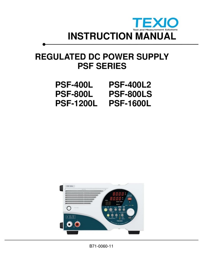
TEXIO
TEXIO PSF-1200L User manual
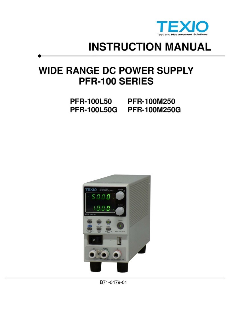
TEXIO
TEXIO PFR-100M250 Manual
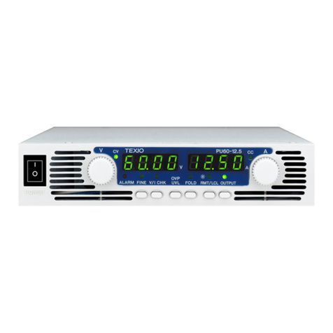
TEXIO
TEXIO PU Series User manual
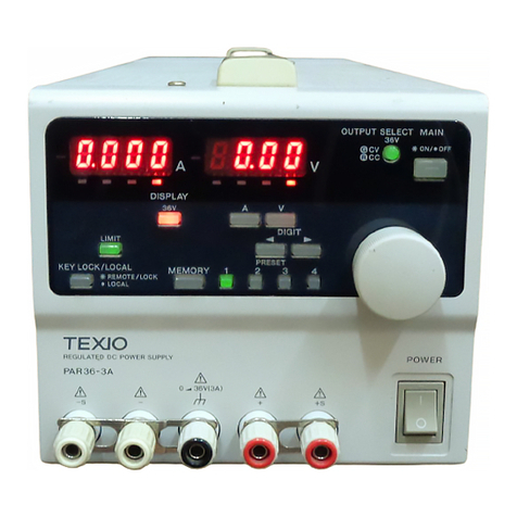
TEXIO
TEXIO PAR-A Series User manual
TEXIO
TEXIO PU6-100 User manual
TEXIO
TEXIO PA10-5B User manual
TEXIO
TEXIO PU6-200 User manual
TEXIO
TEXIO PD18-10AD User manual
TEXIO
TEXIO PW8-3AQP User manual

TEXIO
TEXIO PFR-100 SERIES Owner's manual
