Status SEM315 User manual

D2275-02-02 SEM315 CN4978 WEB User guide
SEM315
DIN RAIL HART ® TEMPERATURE TRANSMITTER
Status Instruments Ltd, Green Lane Business Park, Tewkesbury, Glos. GL20
8DE
Tel: +44 (0)1684 296818 Fax: +44 (0)1684 293746
Email: sales@status.co.uk Web: www.status.co.uk
INDEX
SECTION
CONTENTS PAGE NO.
1.0 DESCRIPTION 1
2.0 SPECIFICATION 1-3
3.0 INSTALLATION 4-5
4.0 HART PROGRAMMING 5-7

D2275-02-02 SEM315 CN4978 WEB User guide
1.0 DESCRIPTION
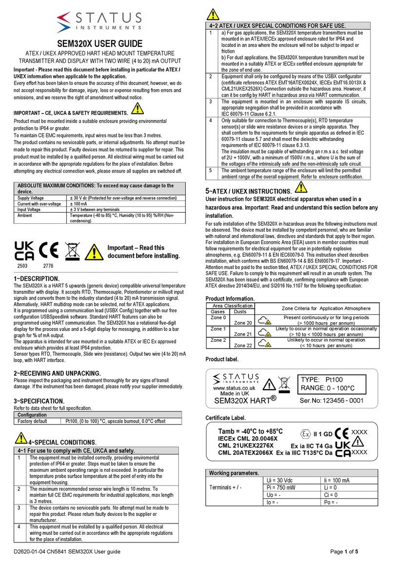
The SEM315 is a HART Din Rail temperature transmitter that accepts commonly used temperature
sensor, slidewire transducer or millivolt signal and converts the output to the industry standard (4 to
20) mA transmission signal.
The software package M-config or a Hart Communicator with the necessary “Device Description” can
be used to program the unit.
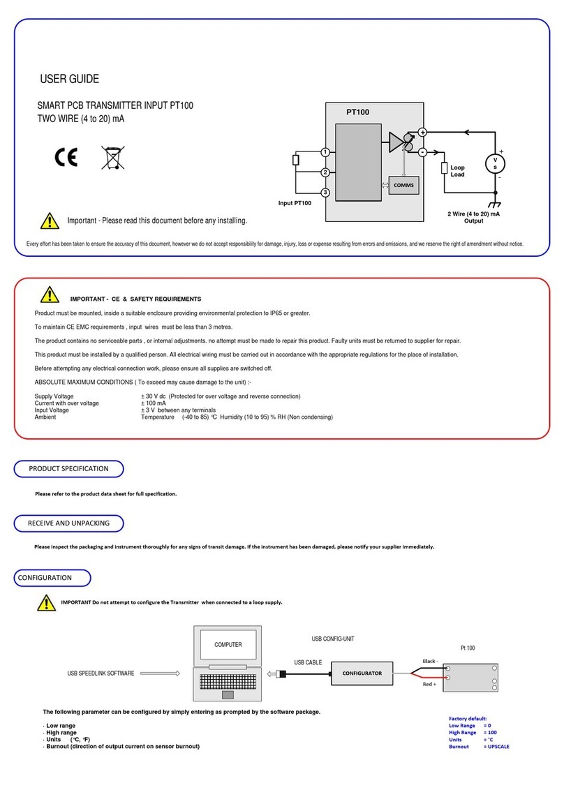
2.0 SPECIFICATION @ 20 °C
2.1 RTD INPUT (Pt100) 2, 3 OR 4 WIRE
Sensor Range (-200 to 850) °C (18 to 390) Ω
Minimum Span 125 °C
Linearisation BS EN60751 (IEC 751) BS 1904
(DIN 43760), JISC 1604, CUSTOM [X] 3
Max Lead Resistance 50 Ωper leg (balanced for 3 wire)
Basic Measurement Accuracy 2±0.01 % FRI ±0.07 % Rdg
(FRI = Full Range Input)
RTD Excitation Current (300 to 500) µA
Thermal Drift Zero 0.008 °C / C
Span 0.01% / °C
2.2 THERMOCOUPLE INPUT
Thermocouple Type Measuring Range4°C Minimum Span1°C
TC Type K -200 to 1370 50
TC Type J -200 to 1200 50
TC Type T -210 to 400 25
TC Type R -10 to 1760 100
TC Type S -10 to 1760 100
TC Type E -200 to 1000 50
TC Type L -100 to 600 25
TC Type N -180 to 1300 50
TC Type [X]3User defined
Linearisation BS EN60584-01 BS 4937/IEC 584-1
(multi segment Polynomials)
Basic Measurement Accuracy 20.04 % FRI ±0.04 % RDG or 0.5 °C
(whichever is greater)
Thermal Drift Span 0.01 % / °C
Cold Junction Error ±0.5 °C
Cold Junction Tracking 0.05 °C / °C
Cold Junction Range (-40 to +85) °C
Page1
2. 3 MILLIVOLT INPUT
Input Voltage Source
Range (-10 to 75) mV
Characterisation Linear, Custom [X] 3
Minimum Span 5 mV
Basic Measurement Accuracy 2±10 µV ±0.07 % Rdg
Input Impedance 10 MΩ
Thermal Drift Zero 0.1 µA / °C
Span 0.01 % / °C
2.4 SLIDEWIRE INPUT
Input 3 Wire potentiometer
Resistance Range (10 to 390) Ω(End to End) Larger values can be
accommodated by fitting a link, see Figure 2.
Characterisation Linear, Custom [X] 3
Minimum Span 15 % of FRI
Basic Measurement Accuracy 20.1 % FRI
Thermal Drift Zero 0.005 % of span / °C
Span 0.01 % / °C
Range (0 to 100) %
2.5 OUTPUT
Burnout Levels Low 3.75 mA , High 21.5 mA
Input out of Range Low 3.8 mA, High 20.5 mA
Output range (4 to 20) mA, Min. 3.75 mA, Max. 21.5 mA
Accuracy ±5 µA
Thermal Drift 1 µA / °C
Supply Voltage 5(10 to 40) V
Supply Voltage effect 0.2 µA / V
Maximum output load [(Vsupply-10)/21.5] KΩ. 250 Ωminimum loop load for correct
HART operation.5
Page 2
24 V
15 V
30 V
40 V
660
500
250 1400
10 V
0
NO HART
OPERATION
NOT RECOMMENDED
SUPPLY
VOLTAGE
MAXIMUM LOAD ( Ω )
OPERATION

D2275-02-02 SEM315 CN4978 WEB User guide
Notes
1Any span may be selected but full accuracy is only guaranteed for spans greater than the
minimum recommended.
2Includes the effect of calibration, linearisation and repeatability.
3Custom characterisation is available pre-programmed at the factory. Contact your nearest
Sales office.
4Consult Thermocouple reference tables for practical temperature ranges.
5For supply voltages over 30V, a minimum loop load of 500 Ωis necessary.
2.6 GENERAL
Input/Output Isolation 500 VAC
Time Constant (Filter Off) 0.5 secs (to 90 % of final value)
Filter Factor Programmable Off / selectable between 1 and 32 seconds / or Adaptive
Warm-up Time 120 seconds to full accuracy
ENVIRONMENTAL
Ambient Operating Range (-40 to 85) °C
Ambient Storage Temperature (-50 to 90) °C
Ambient Humidity Range (10 to 95) % RH non condensing
EMC BS EN 61326
MECHANICAL
Enclosure DIN Rail mounted to fit DIN EN 50022-35
Material ABS
Weight 70 g
Dimensions (90 x 99 x 18.5) mm
Flammability UL94-V0
Connections Tension clamp two terminals and 3.5 jack for comms.
Page 3
3.0 INSTALLATION
3.1 MECHANICAL
The transmitter is designed to mount onto a standard Din Rail. The transmitter should be installed
with adequate protection from moisture and corrosive atmospheres. The transmitter may be mounted
in any orientation.
Care must be taken when locating the transmitter to ensure the ambient temperature remains within
the specified operating range. Figure 1 shows the mechanical layout of the transmitter
Fig 1
(All Dimensions in mm)
3.2 ELECTRICAL
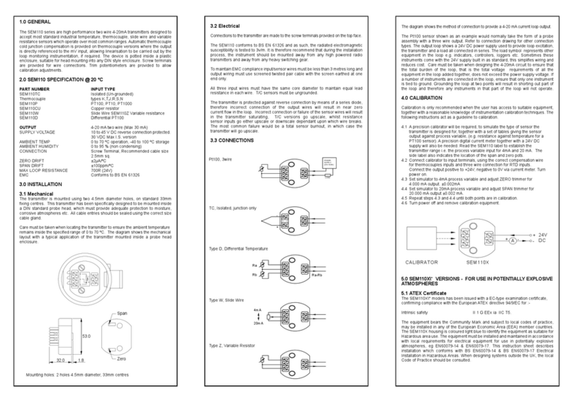
Connections to the transmitter are made to the tension clamp terminals provided on the front face.
Output signal wiring should use screened twisted pair. It is recommended that screened cable is used
for the input signal wires for cable runs greater than one metre. For Pt100 inputs all input wires must
have the same core diameter to maintain equal resistance in each wire.
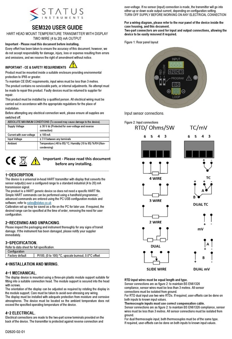
Figure 2 shows the method of connection to provide a (4 to 20) mA current loop output. The output
loop has a voltage power supply used to provide loop excitation. The load symbol represents other
equipment in the loop, normally indicators, controllers or loggers. Care must be taken when designing
the (4 to 20) mA circuit to ensure that the total voltage requirements of all the equipment in the loop
added together, does not exceed the power supply voltage. If a number of instruments are connected
in the loop, ensure that only one instrument is tied to ground. Grounding the loop at two points will
cause a short circuit of part of the loop leading to measurement errors. To maintain CE compliance
the transmitter should be mounted in an enclosure to prevent access to the transmitter during normal
operation.
Page 4
18.25
.5
0.0
6
7
8
10
5
4
3
2
1

D2275-02-02 SEM315 CN4978 WEB User guide
Fig 2
* Resistance Range, (10 to 390) Ω(End to End) Larger values can be accommodated by linking
terminals as shown.
4.0 HART PROGRAMMING
Consult HART website for more details: www.hartcomm.org
4.1 CONNECTION ARRANGEMENT FOR HART COMMUNICATOR
Fig 3.1a
Page 5
Fig 3.1b
4.2 CONNECTION ARRANGEMENTS FOR HART MODEM (e.g. M-CONFIG)
Fig 3.2a
Page 6
R > 250
L
mA
-
+
Current
Meter
+
-
Power
Supply
- Black
Connector
+
HART Modem
(To PC)
-
1 (+)
2 (-)
+ Red
Connector

D2275-02-02 SEM315 CN4978 WEB User guide
Fig 3.2b
Note: Transmitters must be configured individually for Multidrop mode, by setting the Device Number
between 1 and 15. This cannot be done while the transmitters are connected together. The SEM315
can also be configured by connecting the Communicator or HART modem across the load in Figure
3.1a and 3.2a respectively
Page 7
ALSO AVAILABLE:
•Smart In Head Temperature Transmitters
•Din Rail Mounted Temperature Transmitters
•Panel & Field Temperature Indicators
•Temperature Probes
•Trip Amplifiers
•Signal Conditioners
•And many other products
For further information on all products:
Status Instruments Ltd, Green Lane Business Park, Tewkesbury, Glos. GL20 8DE
Tel: +44 (0)1684 296818 Fax: +44 (0)1684 293746
Page 8
Other Status Transmitter manuals