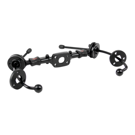
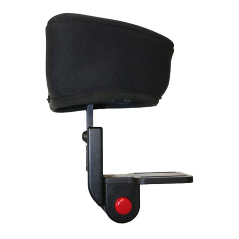
Stealth Products HMO500 User manual

Head Support
Hardware
HMO500
Owner’s Manual - Maintenance Guide
HMO500 Headrest Hardware

1
Table of Contents
Customer Satisfaction ...................................................................... i
General...........................................................................................................i
Important Information............................................................... ii-iii
Warranty .......................................................................................................ii
Supplier Reference....................................................................................ii
Warning Labels..........................................................................................iii
Limited Liability.........................................................................................iii
Testing ..........................................................................................................iii
Design and Function.................................................................... 1-4
Intended Use.............................................................................................. 1
Features........................................................................................................ 1
Installation Plan ........................................................................................ 1
Installation Overview .............................................................................. 2
Mounting Hardware Parts..................................................................... 3
Mounting Hardware Packages and Tools ....................................... 4
Installation Instructions ............................................................ 5-12
Seat Back Mount Installation...........................................................5-6
Depth Adjustment ................................................................................... 7
Angle Adjustment..............................................................................8-10
Adapter Plate Adjustment ..................................................................11
Headrest Installation, Option 1.........................................................12
Headrest Installation, Option 2.........................................................12
First-Time Use.................................................................................13
Dealer Assistance ...................................................................................13
User Testing..............................................................................................13
Conditions of Use ..................................................................................13
Care and Maintenance...................................................................14
Cleaning.....................................................................................................14

i
Customer Satisfaction
Stealth Products is committed to 100% customer satisfaction. Your complete satisfaction is
important to us. Please contact us with feedback or suggestions to help us improve the
quality and usability of our products.
You may reach us at:
General
Read and understand all instructions prior to the use of the product. Failure to
adhere to instructions and warnings in this document may result in property
damage, injury, or death. Product misuse or failure to follow instructions will
void the warranty.
Immediately discontinue use if any function is compromised, if parts are missing
or loose, or if any component shows signs of excessive wear. Consult with your
supplier for repair, adjustment, or replacement.
All persons responsible for fitting, adjustment, and daily use of the devices
discussed in these instructions must be familiar with and understand all safety
aspects of the devices mentioned. In order for our products to be used
successfully, you must read and understand all instructions and warnings, and
maintain our products according to our instructions on care and maintenance.
The installation instructions will guide you through this product’s options and
possibilities.
Instructions are written with the expressed intent of use with standard
congurations. They also contain important safety and maintenance
information, as well as describe possible problems that can arise during use. For
further assistance, or more advanced applications, please contact your supplier
or Stealth Products at (512) 715-9995 or toll free at (800) 965-9229.
Always keep the operating instructions in a safe place so they may be referenced
as necessary.
All information, pictures, illustrations, and specications are based on the product
information that was available at the time of printing. Pictures and illustrations
shown in these instructions are representative examples and are not intended to
be exact depictions of the various parts of the product.
Stealth Products, LLC
104 John Kelly Drive, Burnet, TX 78611
Phone: (512) 715-9995 Toll Free: (800) 965-9229
Fax: (512) 715-9954 Toll Free: (800) 806-1225
info@stealthproducts.com
www.stealthproducts.com
UK Authorized Representative
MDSS GmbH
Schigraben 41
30175 Hannover
Germany
SODIMED SA
Chemin Praz Devant 12
1032 Romanel sur-Lausanne
Switzerland
MDSS-UK RP
6 Wilmslow Road, Rusholme
Manchester M14 5TP
United Kingdom

ii
Important Information
Warranty
Our products are designed, manufactured, and produced to the highest of standards.
If any defect in material or workmanship is found, Stealth Products will repair or
replace the product at our discretion. Any implied warranty, including the implied
warranties of merchantability and tness for a particular purpose, shall not extend
beyond the duration of this warranty. Stealth Products does not warrant damage
due to, but not limited to: misuse, abuse, or misapplication of product, and/or
modication of product without written approval from Stealth Products, LLC. Any
alteration or lack of serial number, where applicable, will automatically void all
warranty.
Stealth Products, LLC Is liable for replacement parts only. Stealth Products, LLC
is not liable for any incurred labor costs.
Stealth Products warrants against failure due to defective materials or
workmanship:
Covers: 2 years
Hardware: 5 years
Electronics: 3 years
In the event of a product failure covered by our warranty, please follow the
procedures outlined below:
Call Stealth Products at (512) 715-9995 or toll free at (800) 965-9229.
Request a Return Authorization (RA) form from the Returns Department and follow
the documentation instructions.
You can download additional copies of this manual by accessing the Stealth
website (https://stlpro.site/stealth-docs) and searching “P17D428” in the search bar
at the top of the page.
Supplier Reference
Supplier:
Telephone:
Address:
Purchase Date:
Model:
These products are designed to be tted, applied, and installed exclusively by
a healthcare professional trained for these purposes. The tting, application,
and installation by a non-qualied individual could result in serious injury.
CAUTION

iii
Important Information
Warning Labels
Warnings are included for the safety of the user, client, operator, and property.
Please read and understand what the signal words DANGER,WARNING,
CAUTION,NOTICE, and SAFETY mean, and how they could aect the user, those
around the user, and property.
Limited Liability
Stealth Products, LLC accepts no liability for personal injury or damage to property
that may arise from the failure of the user or other persons to follow the
recommendations, warnings, and instructions in this manual.
Stealth Products does not hold responsibility for nal integration of nal assembly
of product to end user. Stealth Products is not liable for user death or injury.
Testing
Initial setup and driving should be done in an open area free of obstacles until the
user is fully capable of driving safely.
CAUTION Identies a potential situation which, if not avoided, may result
in minor to moderate injury and property damage.
WARNING Identies a potential situation which, if not avoided, may result
in severe injury,death, and property damage.
DANGER Identies an imminent situation which, if not avoided, may
result in severe injury,death, and property damage.
NOTICE Identies important information not related to injury, but
possible property damage.
SAFETY
Indicates steps or instructions for safe practices, reminders of
safe procedures, or important safety equipment that may be
necessary.

1
Design and Function
Intended Use
The HMO500 is a lightweight, multi-axis mounting bracket for use with Stealth's
headrests. This hardware is designed to provide multi-axis positioning of the head
support, increasing the ability to properly accommodate asymmetrical head
positioning.
Features
The HMO500 hardware:
• is lightweight, multi-axis hardware;
• oers height, depth, and angle adjustments;
• is compatible with all Stealth headrests;
• has a multi-hole pattern to accommodate existing headrests; and,
• is compatible with after-market headrests.
WARNING Stealth does not recommend
the HMO500 for clients with tone.
WARNING Only a qualied service technician
may install the HMO500 hardware.
Installation Plan
Set up an installation plan before installing or making any adjustments to the
hardware. Based on the user's needs, this plan should specify:
• The height required for the headrest.
• The angle the moun�ng bracket and horizontal bar need to be placed in order to
promote the best t of the headrest to the client.

2
Design and Function
CAUTION
Use the proper tools to install and adjust
the HMO500 hardware. The use of improper tools
may cause damage to the device.
Installation
• Install the hardware onto the corresponding headrest for the client.
• Determine the correct placement of the hardware on the chair. If the height
needs to be changed, follow the instructions in the user manual.
• If the angles of the hardware need to be adjusted, loosen the desired screws
and make the adjustments necessary until the headrest is in the correct
placement. Secure the screws.
• Make any nal adjustments necessary and ensure all screws are secure.
CAUTION
Use only the screws provided in the package with the
hardware. Tighten the screws rmly, but not excessively.
Excessive force may damage the unit.
WARNING
Discontinue use if any product's function becomes
compromised or loose, shows signs of excessive wear or
missing parts, or ceases to function as originally intended.

3
Design & Function
Mounting Hardware Parts
Description
ASeat Back Mount
BStop Collar
CHandle
DVertical Bar
EHorizontal Bar
FHeadrest Universal Adapter Plate
GBar Clamp G1 M5 x 0.8 x 12mm SHS (5)
HHeadrest Adapter Mount
D
G
G1
G1
H
E
F
A
C
G1
B

tooltip
3
4
5
6
7
2A
1B
4
Design & Function
Mounting Hardware Packages and Tools
Torque Specications
Description
1Hardware Package 1A 1/4-20 x 5/8 SHS (2)
1B 10-32 x 5/8 SHS (4)
2Hardware Package 2A M5 x 0.8 x 12mm FHS (4)
Tools
33mm Allen Wrench/T-Handle*
44mm Allen Wrench/T-Handle*
53/16" Allen Wrench/T-Handle*
65/32" Allen Wrench/T-Handle*
7Torque Wrench*
Item Torque Requirement
1A 45 in/lb
1B 45 in/lb
2A 40 in/lb
G1* 70 in/lb
* from page 7
* Tools not included
12
1A

tooltip
tooltip
tooltip
5
Installation Instructions
Step 1: Determine the necessary screws in order to properly install the Seat Back
Mount (A) to the chair. Position the Seat Back Mount (A) on the backrest
at the desired height. Secure with corresponding screws provided in the
Hardware Pack (1)
Step 2: Position the Stop Collar (B) on the vertical bar at the approximate height
for installation. Insert and tighten the screw. Refer to the chart on page 4
for torque specications.
OPTION 1
OPTION 2
NOTICE
#10/32 Socket Head Screws (1B) are provided for
Option 1 (4 screws), 1/4-20 Socket Head Screws (1A)
are provided for Option 2 (2 screws).
NOTICE Reference minimum and maximum height adjustment
recommendations before installation of Option 2.
Seat Back Mount Installation
STEP 1
STEP 2

tooltip
¹/₂"
or
more
STEP 3
STEP 4
6
Installation Instructions
Step 3: Ensure handle (C) has been turned counterclockwise before sliding onto
the vertical bar. Insert the vertical bar (D) into the seat back mount. Ensure
the stop collar is ush with the seat back mount.
Step 4: Turn the handle clockwise to tighten the seat back mount and secure the
height adjustment of the vertical bar.
SAFETY
It is recommended that the seat back mount is moved
up no less than 1/2 inch and down no more
than 6 inches from the top of the vertical bar.
tooltip
tooltip
6"
or
less

tooltip
7
Installation Instructions
SAFETY
It is recommended that the minimum depth adjustment is 1/2
inch within the ends of the bar and a maximum of 4 1/2
inches between reference points 1 and 2.
Step 1: Loosen the M5 (G1) screw on the bar clamp with the 4mm T-Handle/Allen
Wrench.
Step 2: Slide the horizontal bar (E) to the desired depth.
Step 3: When the bar has been adjusted to the desired depth, tighten the M5
screw to secure the depth adjustment. Refer to the table on page 4 for
proper torque specications.
Depth Adjustment
STEP 1STEP 2
¹/₂"
or
more
4¹/₂"
or
less
G1
G1

tooltip
8
Installation Instructions
Angle Adjustment
Two points of angle adjustment are available with the HMO500 hardware: the
angle of the horizontal bar can be adjusted, as well as the angle of the headrest
adapter plate.
Step 1: Loosen the M5 (G1) screw from the bar clamp with the 4mm T-Handle/
Allen Wrench.
Step 2: Adjust the horizontal bar (E) to the desired angle. When the desired angle
is achieved, tighten the M5 screw until secure. Refer to the table on page
4 for proper torque specications.
STEP 1
STEP 2
G1
G1
E

STEP 1
STEP 2
G1
G1
F
After the horizontal bar has been properly adjusted and is in the desired position,
the angle adjustment of the adapter plate must be adjusted in order to mount
ush with the headrest. Follow the steps below to adjust the adapter plate in the
correct position.
Step 1: To adjust the angle of the Adapter Plate (F) on the horizontal bar, loosen
the M5 screw (G1) on the bar clamp using the 4mm T-Handle/Allen
Wrench.
Step 2: Angle the adapter plate assembly parallel with the seat back mount..
Secure the M5 screw on the bar clamp Refer to the table on page 4 for
proper torque specications.
NOTICE
If the horizontal bar angle is adjusted, the headrest
adapter plate angle must be adjusted in order to
mount ush with the headrest it will be mounted to.
9
Installation Instructions

tooltip
3¹/₈"
tooltip
10
Installation Instructions
NOTICE Up to 1 3/4" of depth is added
when the horizontal bar is raised to 45°.
NOTICE The horizontal bar should be adjusted
no more than a maximum of 45°.
NOTICE
The height of the Universal Adapter Plate
can move a maximum of 3 1/8" vertically
when the angle of the horizontal bar is raised to 45°.
1³/₄"
45°

11
Installation Instructions
NOTICE
The headrest adapter plate should be angled
no more than 50° to the left or right side
of the center position.
Adapter Plate Adjustment
STEP 1
STEP 3
STEP 2
G1
G1
<50°
left or right
of center
F
To adjust the position of the adapter plate and the direction in which it will mount
to the headrest, follow the directions below:
Step 1: Loosen the M5 screw (G1) on the bar clamp with 4mm T-Handle/Allen
Wrench.
Step 2: Move the adapter plate (F) in the desired direction.
Step 3: When the adjustment is complete, tighten the M5 screw to secure the
headrest in position. Refer to the table on page 4 for the proper torque
specications.

12
Installation Instructions
Headrest Installation, Option 1
To install the HMO500 hardware onto a 3-hole pattern headrest, follow the steps
below:
Step 1: Determine the hole
pattern required for
proper headrest
installation. Align the
headrest to the universal
adapter plate.
Step 2: Secure the headrest to
the adapter plate with
M5 screws. Use the
3mm T-Handle/Allen
Wrench to tighten. Refer
to the table on page 8
for proper torque
specications.
To install the HMO500 hardware onto a 4-hole pattern headrest, follow the steps
below:
Step 1: Align the headrest to the
universal adapter plate.
Step 2: Secure the headrest to the
adapter plate with M5 screws.
Use a 3mm T-Handle/Allen
Wrench to tighten. Refer to the
table on page 8 for proper
torque specications.
Headrest Installation, Option 2
tooltip
tooltip

13
First Time Use
Dealer Assistance
During rst time use by the client, it is advised that the dealer or service technician
assists and explains the dierent congurations to the client. If needed, the dealer
can make nal adjustments.
User Testing
It is important that the customer is fully aware of the installation and how to adjust
the hardware in order for the headrest to be placed in the best position for the
user. As a dealer, proceed as follows:
Is the HMO500 at the proper height for the headrest?
Is the HMO500 placed at the correct angle?
If needed, adjust the hardware to proper position.
Explain to the client the possible problems and how to address them.
Conditions of Use
The HMO500 headrest hardware is intended for use as installed by the dealer, in
accordance to the installation and instructions in this manual.
• The foreseen conditions of use are communicated by the dealer or service
technician to the user and/or attendant during the rst time use.
• If the usage conditions change signicantly, please contact your dealer or a
qualied service technician to avoid excessive wear and tear or unintended
damage.

14
Care and Maintenance
We recommend that the hardware be checked for wear and function on a periodic
basis and replaced, if necessary, by a wheelchair professional.
• Discontinue use after identifying loose or broken components.
• Check and tighten all screws according to the installation instructions.
• Repairs should be done with Stealth parts, fasteners, or items appropriate for
the service needed.
Cleaning
• Surfaces may be wiped clean with a damp cloth and mild, non-abrasive
cleaner.
• Ensure all cleaners are approved for nished steel, aluminum, plastic and
upholstered surfaces.
WARNING Failure to comply with these warnings
could result in serious bodily harm.

(800) 965-9229 | (512) 715-9995 | 104 John Kelly Drive, Burnet, TX 78611
P17D428R2 HMO500.afpub Dec 4, 2023
© 2022, Stealth Products, LLC
WarrantyInformation HomePage OnlineUserManual
Other manuals for HMO500
1
Table of contents
Other Stealth Products Medical Equipment manuals

Stealth Products
Stealth Products SUS9 Swing Away Series User manual

Stealth Products
Stealth Products i2i User manual

Stealth Products
Stealth Products i2i User manual

Stealth Products
Stealth Products MTMD-42 User manual

Stealth Products
Stealth Products Diego User manual

Stealth Products
Stealth Products i2i Guide

Stealth Products
Stealth Products IDCH User manual
Popular Medical Equipment manuals by other brands

St. Jude Medical
St. Jude Medical Optisure LDA220 user manual

Boston Scientific
Boston Scientific VERCISE DBS Information for Prescribers

Saebo
Saebo MAS mini product manual

Thuasne
Thuasne Schulter-Fix Basic Instructions for use

ResMed
ResMed Ultra Mirage user guide

Aqua Phase
Aqua Phase AQ-3000 operating manual