Stealth Products MTMD-42 User manual

USER MANUAL
Medial Hardware
MTMD-42
Stealth’s User Manual and Maintenance Guide for
Medial Thigh Support

i
Customer Satisfaction 1.0
Stealth Products strives for 100% customer satisfaction. Your complete
satisfaction is important. Please contact us with feedback or suggested
changes that will help improve the quality and usability of our products.
You may reach us at:
General
Read and understand all instructions prior to the use of the product. Failure to
adhere to instructions and warnings in this document may result in property
damage, injury, or death. Product misuse due to failure of the following
instructions will void the warranty.
Immediately discontinue use if any function is compromised, if parts are
missing or loose, or if any component shows signs of excessive wear. Consult
with your supplier for repair, adjustment, or replacement.
MDSS GmbH
Schiffgraben 41
30175 Hannover, Germany
Stealth Products, LLC
104 John Kelly Drive, Burnet, TX 78611
Phone: (512) 715-9995
Fax: (512) 715-9954
Toll Free: (800) 965-9229
Toll Free: (800) 806-1225
www.stealthproducts.com

ii
Important Information 2.0
Important Information!
All persons responsible for fitting, adjustment, and daily use of the devices
discussed in these instructions must be familiar with and understand all safety
aspects of the devices mentioned. In order for our products to be used
successfully, you must:
read and understand all instructions and warnings;
maintain our products according to our instruction on care and maintenance; and
ensure devices are installed and adjusted by a trained technician.
Supplier Reference
Supplier:
Telephone:
Address:
Purchase Date:
Model:

iii
Introduction 3.0
Before you install or begin using this product, it is important that you read and
understand the content of these installation and operating instructions. The
installation instructions will guide you through the possibilities with the
MTMD-42.
Instructions are written with the expressed intent of use with standard
configurations. They also contain important safety and maintenance
information. For further assistance, or more advanced applications, please
contact your supplier or Stealth Products at (512) 715-9995 or toll free at
(800) 965-9229.
Always keep the operating instructions in a safe place so they may be
referenced as necessary.
All information, pictures, illustrations, and specifications are based on the
product information that was available at the time of printing. Pictures and
illustrations shown in these instructions are representative examples and are
not intended to be exact depictions of the various parts of the product.
Ordering Documentation
You can download additional copies of this manual by accessing the Stealth
website (https://stlpro.site/stealth-docs) and searching "MTMD-42"in the search
bar at the top of the page.

iv
Warranty 4.0
Our products are designed, manufactured, and produced to the highest of
standards. If any defect in material or workmanship is found, Stealth Products
will repair or replace the product at our discretion. Any implied warranty,
including the implied warranties of merchantability and fitness for a particular
purpose, shall not extend beyond the duration of this warranty. Stealth
Products, LLC does not warrant damage due to, but not limited to:
misuse, abuse, or misapplication of products, and/or
modification of products without written approval from Stealth Products,
LLC.
Any alteration or lack of serial number, where applicable, will
automatically void this warranty.
Stealth Products, LLC is liable for replacement parts only. Stealth Products,
LLC is not liable for any incurred labor costs.
No person is authorized to alter, extend, or waive the warranties of Stealth
Products, LLC.
Stealth Products warrants against failure due to defective materials
or workmanship:
Covers: 2 years
Hardware: 5 years
Electronics: 3 years
In Case of Product Failure
In the event of product failure covered by our warranty, please follow the
procedures outlined below:
1. Call Stealth at (512) 715-9995 or toll free (800) 965-9229.
2. Request a return authorization form (RA) from the Returns Department and follow
documentation instructions.

v
Table of Contents 5.0
1.0 Customer Satisfaction……………………………………………………………i
2.0 Important Information…………………………………………………….…….ii
3.0 Introduction………………………………………………………………………...iii
4.0 Warranty………………………………………………………………………….….iv
5.0 Table of Contents………………………………………………………………….v
6.0 Warning Labels…………………………………………………………………….vi
6.1 Warning Labels……………………………………………………………………………..….vi
6.2 Limited Liability………………………………………………………………………………..vi
6.3 Testing…………………………………………………………………………………………..….vi
7.0 Design and Function…………………….………………………….………...….1
7.1 Available Hardware Mounting Options……….…………….………….………….1
8.0 Mounting..…………………………………………………………………………..2
8.1 Standard Mounting Options……...…………………………………………...……….2
Fixed…………………………………………………………………………………...…………...2
Removable………………………………………………………………………...…………….2
9.0 Operating……………...………..………………………………..…………...…….3
9 .1 Operating Abductors……..….……………………………………………………..……...3
Swing Away Flip Down……………………………………………………………...…….3
Removable………………….……………………………………………………………..…….3
10.0 Adjustments……………………………………………………………………….4
10.1 Adjusting Pad Height…………………………………………………………...…….…..4
10.2 Pad Offset Adjustment………………………………………………………...………...4
10.3 Angle Adjustment……………………………………………………………...…………..5
11.0 First Time Use…………………………………………………………...………..6
11.1 Dealer Assistance………………………………………………...………………………...6
11.2 User Testing……………………………………………………………...……...…………...6
11.3 Condition Of Use…………………………………………………………...…………...…6
12.0 Maintenance………………………………………………………………………7
12.1 Care and Maintenance……………………………………………………..……………7
12.2 Cleaning…………………….………………………………………….……………………….7

vi
Warning Labels 6.0
Warning Labels 6.1
Warnings are included for the safety of the user, client, operator,and property.
Please read and understand what the signal words DANGER, WARNING,
CAUTION, NOTICE, and SAFETY mean, and how they could affect the user,
those around the user, and property.
Limited Liability 6.2
Stealth Products, LLC accepts no liability for personal injury or damage to
property that may arise from the failure of the user or other persons to follow
the recommendations, warnings, and instructions in this manual.
Testing 6.3
Initial setup and driving should be done in an area free of obstacles until the
user is fully capable of driving safely.
The MTMD-42 should always be tested without any person sitting in the
wheelchair until every alteration of the physical installation or adjustment
is complete.
NOTICE
Identifies important information not related to injury, but
possible property damage.
SAFE TY
Indicates steps or instructions for safe practices, reminders of
safe procedures, or important safety equipment that may be
necessary.
CAUTION Identifies a potential situation which, if not avoided,may
result in minor to moderate injury and property damage.
WARN ING
Identifies a potential situation which, if not avoided,
may result in severe injury, death,and/or property
damage.
DANG ER Identifies an imminent situation which (if not avoided)
may result in severe injury, death,and property damage.

1
Design and Function 7.0
MTHW-600
Fixed Posion
Removable hardware with knob fastener for
easy adjustments
Maximum height of 4 3/4inches
1/4-20 Buon Head Screws are included. Use a 5/32
T– Handle for height adjustments and pad mount
screws.
A 3/16 tool is used for the 1/4-20 Socket
Head Screws.
MTHW-610
Flipped Down Hardware
Removable hardware with 180° ip
down mechanism
Depth can be adjusted up to 8 inches
Maximum height of 4 3/4inches
1/4-20 Buon Head Screws are included. Use a
5/32 T-Handle for height adjustments and pad
mount screws.
MTHW-640
Fixed hardware with height adjustment
180° ip down capability
Height can be adjusted up to 3 inches
Depth can be adjusted up to 2 inches
1/4-20 Buon Head Screws are included. Use a
5/32 T-Handle for height adjustments and pad
mount screws.
Available Hardware Mounting Options 7.1

2
Mounting 8.0
Standard Mounting Options 8.1
Fixed
1. Insert the 1/4 20x 1/2” Socket Head Screws (F) (Qty. 4) through the drilled slots into the
boom of the seat pan and ghten.
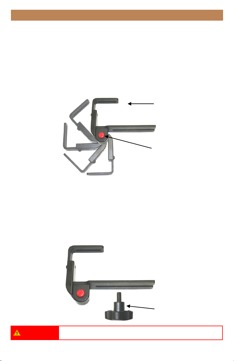
Removable
1. Insert the 1/4 20x 3/4” Socket Head Screws (G) (Qty. 2) through the drilled out slot into
the boom of the seat pan and ghten.
2. Screw the threaded Knob Bolt (H) through the drilled out slot and into the seat pan.
3. Tighten by turning in a clockwise direcon.
(F)
(G)
(H)
WAR NING Do not overtighten screws.
3
Operating 9.0
Operating Abductors 9.1
Swing Away/Flip Down
To remove the abductor:
1. Depress the quick release buon (A).
2. Press against the pad mount (B) unl the pommel is out of the way.
3. To return the pad, depress the quick release buon while returning the pad mount back
into its upright and locked posion.
Removable
To remove the abductor:
1. Loosen the knob (C) by turning in a counter clockwise direcon.
2. When the bracket becomes loose, slide the pommel out from beneath.
3. To return the pommel to its original posion, slide the mounng bracket between the
knob bolt.
4. Tighten by turning in a clockwise direcon.
(B)
(A)
WAR NING Do not overtighten screws.
(C)

4
Adjustments 10.0
Pommel Modification
The adjustable medial pad modicaon (MTMD-42) is an upgraded pad opon that allows
adjustment in mulple angles/planes.
The purpose of this adjustment is to allow for a more natural t and comfort for the client.
This current modicaon is compable with xed/removable ip down hardware
(MTHW-600/610/640) and comes with two 3x5 pads and slip cover.
Adjusting Pad Height 10.1
To adjust pad height:
1. Loosen the 1/4-20 x 1/2” Buon Head Screw (D).
2. Slide the pad into the desired posion.
3. Re-ghten screws with a 5/32 T- Handle.
(D)
Pad Offset Adjustment 10.2
To adjust pad offset:
1. Loosen 10-32 x 1/2” Buon Head Screws (E).
2. Slide pad along track into desired posion.
3. Re-ghten screws with a 5/32 T-Handle.
(E)

5
Adjustments 10.0
Angle Adjustment 10.3
To adjust pad angle:
1. Loosen the 1/4-20 x 1 1/4” Flat Head Screw (F).
2. Open/close abductor to the desired posion
3. Re-ghten screw with a 3/16 T-Handle
(F)
WARN ING Do not overtighten screws.
*Medial support above shown with slip cover.

6
First-Time Use 11.0
11.1Dealer Assistance
During first time use by the client, it is advised that the dealer or service
technician not only assembles the product, but also explains the
configuration to the customer (i.e., the user and/or the attendant). If
necessary, the dealer can make final adjustments.
WAR NIN G
The Medial Thigh Hardware should only be prescribed and fitted by qualified
health care professionals.
User Testing 11.2
It is important that the customer is fully aware of the installation and how the
headrest can be adjusted in order to gain the best positioning possible. As a
dealer, proceed as follows:
Explain and show the customer how you have executed the installaon, and explain
the funcon.
Have the user test the position of the MTMD-42.
Is the hardware in the proper posion for the client?
Can the user safely operate the chair?
Is the placement of the MTMD-42 in an opmal posion for the user?
If needed, adjust the hardware to the proper position.
Explain to the customer any possible issues and how to address them.
Conditions of Use 11.3
The MTMD-42 is intended for use as installed by the dealer, in accordance to
the installation instructions in this manual:
The foreseen conditions of use are communicated by the dealer or service technician to
the user and/or attendant during the first-time use.
If the conditions of use change significantly, please contact your dealer or a qualified
service technician to avoid excessive wear and tear or unintended damage.

7
Maintenance 12.0
Periodically check the hardware for loose screws or worn parts.
Check the headrest for any foam breakdown and/or metal coming through the foam. This
could be potenally dangerous for the client.
To wash the cover, remove the foam from the medial hardware. Machine wash in cold
water, delicate cycle, and drip dry.
It may be required to ghten the set screw if the swing away mechanism is loose.
If the hardware unintenonally swings away or does not lock into place when put in the
operang posion, the set screw will need to be loosened.
Care and Maintenance 12.1
Cleaning 12.2
For minor stains:
Scrub aluminum with water and use a brush or sponge.
For more serious stains:
Use an abrasive sponge with a gentle household cleaner or glass cleaner.
SAFE TY Replace or repair parts as needed.
WARN ING
Any foam breakdown or metal showing through could be potentially dangerous
for the user.
DANGE R
Failure to comply with these warnings could result in serious bodily harm.

a
NOTES 13.0

Stealth Products, LLC. • info@stealthproducts.com • www.stealthproducts.com
+1(800) 965-9229 | +1(512) 715-9995 | 104 John Kelly Drive, Burnet TX 78611
P91D280 Revision Date 2019-12-17
Table of contents
Other Stealth Products Medical Equipment manuals

Stealth Products
Stealth Products Diego User manual

Stealth Products
Stealth Products i2i User manual

Stealth Products
Stealth Products IDCH User manual

Stealth Products
Stealth Products i2i Guide

Stealth Products
Stealth Products SUS9 Swing Away Series User manual

Stealth Products
Stealth Products HMO500 User manual

Stealth Products
Stealth Products i2i User manual


