SteelMax PB-5 User manual

The tools of innovation.
15335 E. Fremont Drive, Centennial, CO 80112
1–87STEELMAX, FAX 303–690–9172
www.steelmax.com [email protected]
OPERATOR’S MANUAL
P
PB
B-
-5
5
/
/
P
PB
BE
E-
-5
5
/
/
P
PB
BC
C-
-5
5
PIPE BEVELING MACHINE

Contents
1. GENERAL INFORMATION............................................................................................... 3
1.1. Application................................................................................................................. 3
1.2. Technical data............................................................................................................ 3
1.3. Equipment included ................................................................................................... 4
1.4. Dimensions................................................................................................................ 5
1.5. Design ....................................................................................................................... 7
2. SAFETY PRECAUTIONS.................................................................................................. 8
3. STARTUP AND OPERATION..........................................................................................10
3.1. Installing the jaw blocks and tool bits ........................................................................10
3.2. Installing (removing) the mandrel and adjusting the clearance..................................11
3.3. Installing the motor....................................................................................................12
3.4. Clamping the machine into the pipe..........................................................................13
3.5. Preparing the air (for machine with air motor) ...........................................................14
3.6. Operating..................................................................................................................14
3.7. Troubleshooting the electric motor............................................................................16
3.8. Troubleshooting the battery motor.............................................................................16
3.9. Replacing the spindle disk ........................................................................................17
3.10. Facing and beveling at the same time.....................................................................18
4. ACCESSORIES...............................................................................................................19
4.1. Tool bits for carbon steel...........................................................................................19
4.2. Tool bits for stainless steel........................................................................................21
4.3. Air motor...................................................................................................................22
4.4. Electric motor............................................................................................................22
4.5. Battery motor ............................................................................................................22
4.6. Air preparation unit....................................................................................................23
4.7. 5.2 Ah battery ...........................................................................................................23
4.8. Battery charger .........................................................................................................23
4.9. 75 mm spindle disk...................................................................................................24
4.10. 140 mm spindle disk set..........................................................................................24
4.11. Ratchet wrench.......................................................................................................25
4.12. Small expanding mandrel........................................................................................26
4.13. Coolant ...................................................................................................................26
5. EXPLODED DRAWINGS AND PARTS LIST....................................................................27
6. DECLARATIONS OF CONFORMITY...............................................................................30
7. WARRANTY CARD..........................................................................................................33

PB-5 / PBE-5 / PBC-5
PB-5 / PBE-5 / PBC-5 Operator’s Manual
3
1. GENERAL INFORMATION
1.1. Application
The PB-5 / PBE-5 / PBC-5 is apipe beveling machine designed to mill pipes made of
carbon and stainless steel, aluminum alloys, and copper-nickels. Depending on the tool
bit used, the machine allows external beveling, internal beveling, J-beveling, internal
calibration, and facing pipes from inner diameters of 32 mm (1.26″)to outer diameters
of 114 mm (4.49″). You can install up to three tool bits at the same time.
An optional 140 mm spindle disk set allows the machine to bevel pipes with outer
diameters up to 140 mm. Using an optional 75 mm spindle disk, ratchet wrench, or
both, helps working in places hard to reach. An optional small expanding mandrel
allows machining pipes with inner diameters from 25 mm to 33 mm (0.98–1.30″).
1.2. Technical data
PB-5
PBE-5
PBC-5
Pressure
0.6 MPa (87 psi)
–
–
Voltage
–
1~ 110–120 V, 50–60 Hz
1~ 220–240 V, 50–60 Hz
18 V DC, 5.2 Ah
Air motor
Modec
NT10RT0851FCA1F-CO
–
–
Electric motor
–
Metabo
SBEV 1100-2 S
Metabo
BS 18 LTX Impuls
Connection
CEJN 410 DN 10.4
R 1/2″BSPT fitting for
quick-coupling
Electrical plug
Battery connection
Air consumption
1400 l/min (50 CFM)
–
–
Power
800 W
1100 W
–
Pipe diameter
32 mm ID to 114 mm
OD (1.26–4.49″)
32 mm ID to 114 mm
OD (1.26–4.49″)
32 mm ID to 114 mm
OD (1.26–4.49″)
Maximum pipe
wall thickness for
outer diameter
up to 114mm
12 mm (0.47″)
12 mm (0.47″)
12 mm (0.47″)
114–124mm*
10 mm (0.39″)
10 mm (0.39″)
10 mm (0.39″)
124–132mm*
8 mm (0.31″)
8 mm (0.31″)
8 mm (0.31″)
132–140mm*
6 mm (0.24″)
6 mm (0.24″)
6 mm (0.24″)
Rotational speed without load
180 rpm
–
0–50 rpm (gear 1)
0–180 rpm (gear 2)
Nominal rotational speed
90 rpm
0–113 rpm (gear 1)
0–318 rpm (gear 2)
–
Protection class
–
II
–
Required ambient temperature
0–40°C (34–104°F)
0–40°C (34–104°F)
0–40°C (34–104°F)
Weight with motor
10 kg (22 lbs)
11 kg (24 lbs)
10 kg (22 lbs),
includes battery
* Available with the optional 140 mm spindle disk set.

PB-5 / PBE-5 / PBC-5
PB-5 / PBE-5 / PBC-5 Operator’s Manual
4
1.3. Equipment included
1
Beveling machine (without tool bits)
1 unit
2
Metal box
1 unit
3
Jaw blocks (number 1, 2, 3, 4, 5, 6)
3 sets
4
Coolant container
1 unit
5
Tool container
1 unit
6
13 mm socket wrench
1 unit
7
6 mm hex wrench
1 unit
8
5 mm hex wrench
1 unit
9
4 mm hex wrench with handle
1 unit
10
3 mm hex wrench with ball end
1 unit
11
Air motor
Option
12
Electric motor
Option
13
Battery motor
Option
–
Operator’s Manual
1 unit
1
2
3
4
5
6
7
8
9
10
11
12
13

PB-5 / PBE-5 / PBC-5
PB-5 / PBE-5 / PBC-5 Operator’s Manual
5
1.4. Dimensions
380 mm (15″)
232 mm (9″)
539 mm (21″)
577 mm (23″)
433 mm (17″)
232 mm (9″)

PB-5 / PBE-5 / PBC-5
PB-5 / PBE-5 / PBC-5 Operator’s Manual
6
434 mm (17″)
468 mm (18.4″)
232 mm (9″)

PB-5 / PBE-5 / PBC-5
PB-5 / PBE-5 / PBC-5 Operator’s Manual
7
1.5. Design
Fig. 1. View of PB-5 and of PBE-5 electric motor and PBC-5 battery motor
Handle
Clearance
adjustment
unit
Expanding mandrel
118 mm spindle disk
Air motor
ON/OFF lever
Air connection
Draw nut
Feed
indicator
ON switch lock
ON/OFF switch
Rotation direction switch
(must be set as shown)
Gear switch
Speed adjustment dial / LED
Rotation direction switch
(must be set as shown)
ON/OFF switch
with speed adjustment
Gear switch
Torque adjustment dial
Battery
LED activation button
LED
Operation mode switch
(must be set as shown)

PB-5 / PBE-5 / PBC-5
PB-5 / PBE-5 / PBC-5 Operator’s Manual
8
2. SAFETY PRECAUTIONS
1. Before use, read this Operator’s Manual and complete a training in occupational
safety and health.
2. Use only motors specified in the technical data.
3. Use only in applications specified in this Operator’s Manual.
4. Make sure that the machine has all parts and they are genuine and not damaged.
5. Make sure that the specifications of the air (power) source are the same as those
specified on the rating plate.
6. Supply themachine with air motor only with clean and lubricated air. Make sure
that the air source has an air preparation unit that contains a filter, regulator, and
lubricator.
7. Do not pull the hose (cord). This can cause damage and serious injury.
8. Keep untrained bystanders away from the machine.
9. Before each use, ensure the correct condition of the machine, air (power) source,
supply hose (power cord, battery), quick coupling (plug), control parts, and tool bits.
10. Before each use, make sure that no part is cracked or loose. Make sure to
maintain correct conditions that can have an effect on the operation of the
machine.
11. Avoid accidental starts. Do not put the machine so that the motor will start. Do not
carry the machine with air motor by holding the ON/OFF lever.
12. Keep the machine dry. Do not expose the machine to rain, snow, or frost.
13. Keep the work area well-lit, clean, and free of obstacles.
14. Do notuse nearflammable materials, orin explosive environments.
15. Attach the pipe so that it will not fall or roll.
16. Use only tool bits specified in this Operator’s Manual.
17. Do not use tool bits that are dull or damaged.
18. Attach the tool bits with two screws. Remove wrenches from the work area
before you connect the machine to the air (power) source.
19. Use eye and ear protection, protective footwear, and protective clothing. Do not
use loose clothing.
20. Use an electric/battery motor only after you set the rotation direction switch and the
operation mode switch as shown in Fig. 1. Using left rotation or impulse mode (the
switches set to the opposite positions) can damage the machine.

PB-5 / PBE-5 / PBC-5
PB-5 / PBE-5 / PBC-5 Operator’s Manual
9
21. Do not touch chips or moving parts. Do not let anything catch in moving parts.
22. After each use, clean the machine with a dry cotton cloth and no chemical
agents. Do not remove chips with bare hands.
23. Maintain the machine and install/remove parts and tool bits only after you unplug
the machine from the air (power) source or remove the battery.
24. Repair only in a service center appointed by the seller.
25. If the machine falls, is wet, or has any damage, stop the work and immediately
send the machine to the service center for check and repair.
26. Do not leave the machine when it operates.
27. If you are not going to use the machine, remove the tool bits from the sockets.
Then, remove the machine from the work area and keep it in a safe and dry
place.
28. If you are not going to use the machine for an extended period, put anti-corrosion
material on the steel parts.
PB-5 / PBE-5 / PBC-5
PB-5 / PBE-5 / PBC-5 Operator’s Manual
10
3. STARTUP AND OPERATION
3.1. Installing the jaw blocks and tool bits
Use the table that follows to select the correct jaw blocks for the diameter of the pipe.
Pipe inner diameter
Jaw blocks
number
[mm]
[inch]
32–43.5
1.26–1.71
–
43–55
1.69–2.17
1
54–66.2
2.13–2.61
2
64.7–76.9
2.55–3.03
3
74.9–87.1
2.95–3.43
4
85.2–97.4
3.35–3.83
5
94.8–107
3.73–4.21
6
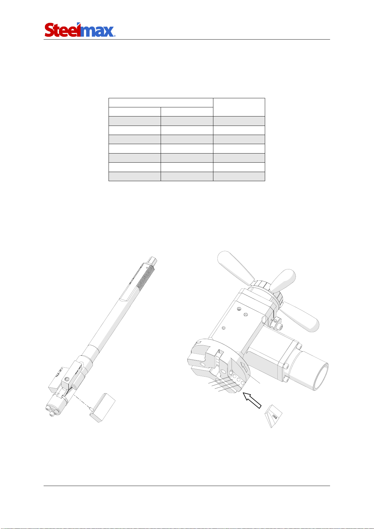
Use the 3 mm hex wrench to attach the jaw blocks to the expanding mandrel (1,
Fig. 2). Then, select up to three tool bits suitable to planned use, and put them in the
sockets. Point the blades in the rotation direction (2). Next, use the 4 mm hex wrench
and two of the screws (3)to attach each tool bit. Make sure that the pressing
surfaces of the screws are in full contact with the tool bits.
Fig. 2. Installing the jaw blocks and tool bits
1
2
3

PB-5 / PBE-5 / PBC-5
PB-5 / PBE-5 / PBC-5 Operator’s Manual
11
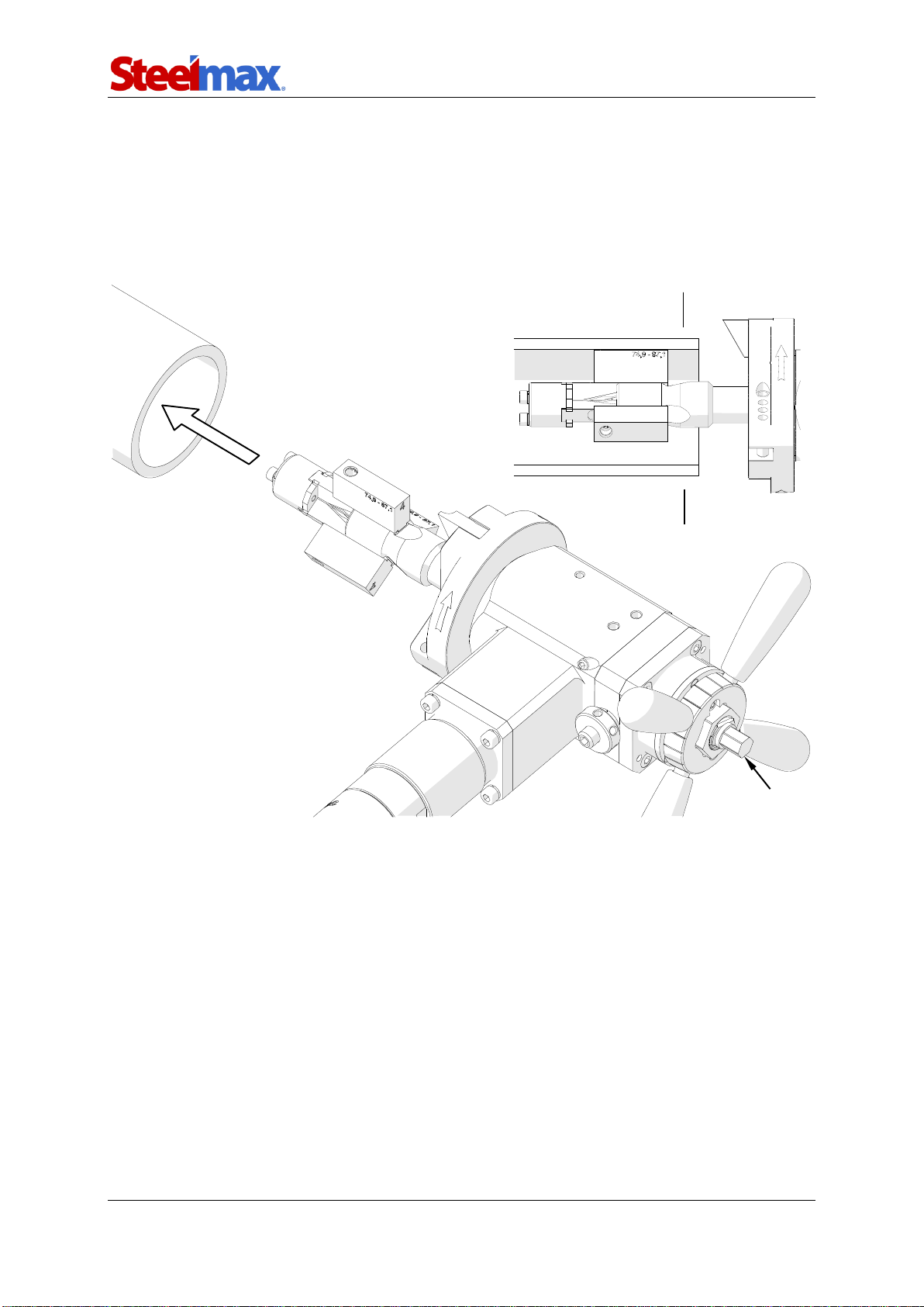
3.2. Installing (removing) the mandrel and adjusting the clearance
Loosen the nut and use the 6 mm hex wrench to loosen the set screw (1, Fig. 3), and
put the mandrel into the machine (2). Make sure that tool bits installed are not in
contact with the mandrel. Next, rotate the handles to the right (3) by at least 10 turns
until the mandrel engages with the machine fully. Tighten the set screw (4)and check
if you can easily rotate the handles in both directions. If the screw is too tight, loosen it
lightly. Finally, tighten the lock nut (5).
Fig. 3. Installing the mandrel into the machine
If the mandrel becomes loose causing vibrations of the tool bits during machining, do
the above actions without removing the mandrel from the machine.
To remove the mandrel, loosen the nut and use the 6 mm hex wrench to loosen
the set screw (1,Fig. 3) by at least one turn. Then, rotate the handles to the left to
remove the mandrel.
1
2
4
5
3
3

PB-5 / PBE-5 / PBC-5
PB-5 / PBE-5 / PBC-5 Operator’s Manual
12
3.3. Installing the motor
When you use the air motor, put it into the machine (1, Fig. 4) so that the arbor is in
the socket (2). Then, rotate the motor to the left (3) to tighten.
To attach the electric/battery motor, put the clamping ring (4) onto the machine.
Attach the correct driver (5) to the motor. Put the motor into the machine (6) so that
the arbor is in the socket (2). Then, use the 6 mm hex wrench to tighten the clamping
ring (7).
In the electric motor, set the rotation direction switch as shown in Fig. 1. In the
battery motor, set the rotation direction switch and the operation mode switch as
shown in Fig. 1.
Fig. 4. Installing the air, electric, and battery motor
1
2
3
5
5
6
7
5
4
5
5
PB-5 / PBE-5 / PBC-5
PB-5 / PBE-5 / PBC-5 Operator’s Manual
13
3.4. Clamping the machine into the pipe
Put the machine into the pipe (1, Fig. 5) to set the tool bits at least 3 mm (0.12″) from
the pipe end. Then, use the 13 mm socket wrench to rotate the draw nut (2) to the
right to expand the jaw blocks and clamp the machine into the pipe. Make sure that
the jaw blocks are put further than the surface after machining (3).
Fig. 5. Clamping the machine into the pipe
2
1
3
3
PB-5 / PBE-5 / PBC-5
PB-5 / PBE-5 / PBC-5 Operator’s Manual
14
3.5. Preparing the air (for machine with air motor)
Connect the machine to a correctly prepared air source of sufficient purity. Make sure
that all inner diameters of the air source (including the supply hose and fittings) are of
at least 10 mm (0.4″). Make sure that the air source has an air preparation unit that
contains a filter, regulator, and lubricator (FRL).
Maintain the FRL unit as required. Keep the water trap drained, filter cleaned,
and the lubricator oil reservoir filled so that there is a drop of oil every 2–5 seconds.
Use oil whose ignition temperature is more than 260°C (500°F). If you are not going
to use the machine for at least 24 hours, increase the supply of oil and let the motor
operate for 2–3 seconds. This will prevent rusting and degrading of the rotor vanes.
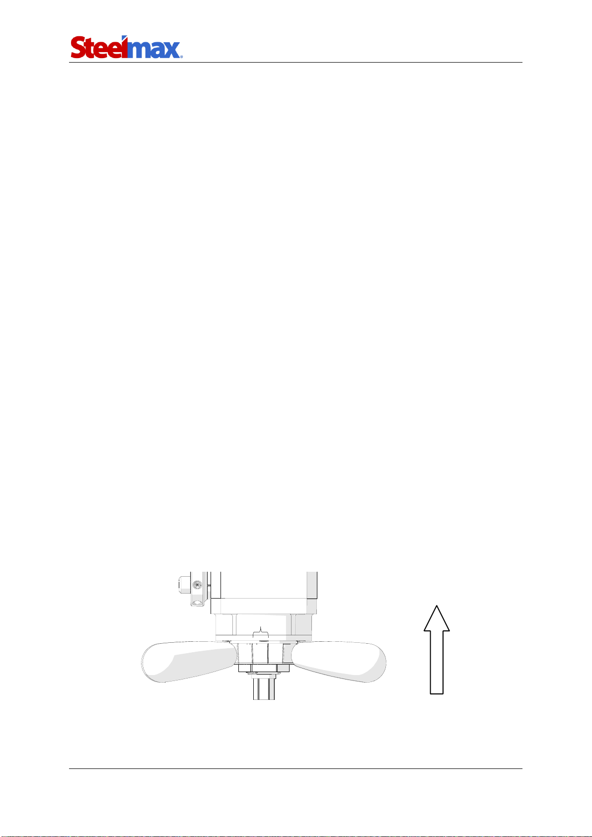
3.6. Operating
After you connect the machine to the correct supply, press the ON/OFF lever to start.
In the electric motor, set the gear 1. In the battery motor, set the gear 1 and the
maximum torque. Then, press and hold the ON/OFF switch. To lock the switch in the
position ON (not available in the battery motor), press the ON switch lock before you
release the ON/OFF switch. To adjust the speed, use the dial or, in the battery motor,
change the force that you apply on the ON/OFF switch.
Apply the coolant on the working edge. Then, rotate the handles to the right to
bring the tool bits close to the pipe. If the pipe end is not perpendicular to the pipe
axis, the tool bit will cut only a small part of the pipe during initial rotations. Thus, use
a low feed rate until the tool bit is in continuous contact with the pipe during at least
one rotation. The feed is 0.11 mm (0.004″) per graduation (Fig. 6) or 2 mm (0.08″) per
one full turn of the handles.
Fig. 6. View of the feed indicator
Rotate the handles to the right to continue machining. Use such a feed rate so
that the chip is continuous. If the feed rate is too low, only small chips are removed.
Feed direction
0.11 mm (0.004″)

PB-5 / PBE-5 / PBC-5
PB-5 / PBE-5 / PBC-5 Operator’s Manual
15
If the feed rate is too high, machining is difficult and the chips are rough or torn.
Do not allow the tool bit to burnish the surface. If chatter problems occur, decrease
the feed rate and the speed. Then, make sure that the tool bits that you use are
sharp and are of correct type for the material. Stainless steel can harden during work.
Thus, cut stainless steel with a high enough feed, 0.08–0.15 mm (0.003–0.006″) per
rotation, to cut under the hardened surface.
If the electric motor becomes overloaded, the motor shuts off. However, do not let
the motor overload. If possible, cuthardmaterials with a low feed rate and speed.
After the pipe end is machined fully, stop rotating the handles and allow several
more turns of the spindle to improve the finish of the surface. Then, use the ON/OFF
lever/switch to turn off the motor, and wait until the rotation stops. Rotate the handles
to the left to move the tool bits away from the pipe end to at least 3 mm (0.12″). Then,
rotate the 13 mm socket wrench to the left to loosen the draw nut and release the
clamping, and remove the machine from the pipe.
Clean the pipe with petroleum ether.
Clean the machine with a dry cotton cloth and no chemical agents.

PB-5 / PBE-5 / PBC-5
PB-5 / PBE-5 / PBC-5 Operator’s Manual
16
3.7. Troubleshooting the electric motor
If the LED is on, the motor power has been decreased. This prevents overheating of
the motor as a result of frequent overload. To decrease the temperature of the motor,
let the motor operate with no load at the maximum speed.
If the LED flashes fast, the automatic restart has been prevented after a power
failure. Then, to start the motor, turn it off and on.
If the LED flashes slow, the carbon brushes are almost worn and the motor
has been shut off. Replace the brushes with new ones specified by the manufacturer
of the motor.
3.8. Troubleshooting the battery motor
If the motor is frequently overloaded for extended periods, it will be shut off. To stop
the beeping signal, release the ON/OFF switch. If you feel that the motor or the
battery is warm, before use wait until its temperature decreases. To decrease the
temperature more quickly, let the motor operate with no load at the maximum speed.
The motor can also shut off if the machine jams in the workpiece. To continue
work, release the ON/OFF switch and press it again. Do not let the machine jam in
the workpiece.
If the LED flashes, the battery is almost discharged. To check the charge level,
press the LED activation button. If the battery is discharged fully, charge the battery
or replace to a fully charged.

PB-5 / PBE-5 / PBC-5
PB-5 / PBE-5 / PBC-5 Operator’s Manual
17
3.9. Replacing the spindle disk
Loosen the nut and use the 6 mm hex wrench to loosen the set screw (1, Fig. 7) by
at least one turn. Then, rotate the handles to the left (2) to remove the mandrel (3).
Fig. 7. Removing the mandrel from the machine
Use the 5 mm hex wrench (1, Fig. 8) and remove the spindle disk (2). Then, install
the new disk (3) onto the pin (4) and tighten with the same screws.
Fig. 8. Replacing the spindle disk
1
2
3
4
1
2
3

PB-5 / PBE-5 / PBC-5
PB-5 / PBE-5 / PBC-5 Operator’s Manual
18
3.10. Facing and beveling at the same time
When you face and bevel at the same time, use short or long beveling tool bit
depending on the pipe diameter (Fig. 9).
Fig. 9. Positioning the facing tool bit and a short or long beveling tool bit
F0-30 facing tool bit
Short tool bit
Long tool bit
Short tool bit
Short or long
tool bit
Long tool bit
Long tool bit
Short or long
tool bit
Short tool bit

PB-5 / PBE-5 / PBC-5
PB-5 / PBE-5 / PBC-5 Operator’s Manual
19
4. ACCESSORIES
4.1. Tool bits for carbon steel
NOZ-000031
F0-30
0° facing tool bit
NOZ-000032
B30
30° beveling tool bit*
NOZ-000033
B30d
30° beveling tool bit**
NOZ-000036
B375
37.5° beveling tool bit*
NOZ-000037
B375d
37.5° beveling tool bit**
NOZ-000040
B45
45° beveling tool bit*
NOZ-000041
B45d
45° beveling tool bit**
* For diameters over 56 mm, if works together with 0° facing tool bit.
** For diameters under 83 mm, if works together with 0° facing tool bit.

PB-5 / PBE-5 / PBC-5
PB-5 / PBE-5 / PBC-5 Operator’s Manual
20
NOZ-000052
IC15-40 –on the left
15° internal calibration tool bit
NOZ-000053
IC15-40 –on the right
(for diameters over 56 mm)
15° internal calibration tool bit
NOZ-000087
IB12-60
12° internal beveling tool bit
NOZ-000058
J10-R6
10° J-beveling tool bit
NOZ-000057
J15-R2
15° J-beveling tool bit
NOZ-000059
J20-R8
20° J-beveling tool bit
NOZ-000088
J20-R1
20° J-beveling tool bit
This manual suits for next models
2
Table of contents
Other SteelMax Power Tools manuals


