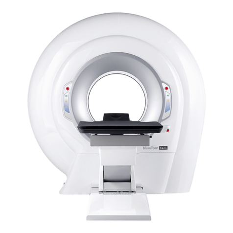
CEFLA NEWTOM 5GXL User manual

97050723
Rev. 4
05.02.2018
NewToms 5G XL –Service Manual
EN

NOTES
This document is provided as a consultation manual intended for the device technicians.
CEFLA s.c. follows a policy based on the constant development and update of the product. For this reason, it
reserves the right to change the content of this manual without prior notice.
This document can not be modified, copied, reproduced, distributed, saved on magnetic or optical supports,
or published on websites and other on-line services, in full or in part, without the prior written authorisation of
CEFLA s.c.
The original version of this manual is in English.
NEWTOM™ VG is a trade mark of CEFLA s.c.
All other products and trade names mentioned in this document are registered marks of the relevant
manufacturers.
INFORMATIVE NOTE OF THE MANUFACTURER ON THE MEDICAL DEVICES
The medical device referred to in this manual consists of a scanner and a control, display and calculation
unit (Main Workstation). Such device, as delivered and configured by the production and assistance
technical personnel, is an X-ray device compliant with the safety requirements set forth by the Italian
Legislative Decree of 19 September 1994, no. 626 implementing Directives 89/391/EEC, 89/654/EEC,
89/655/EEC, 89/656/EEC, 90/269/EEC, 90/270/EEC, 90/394/EEC and 90/679/EEC concerning the
improvement of the health and safety of workers in the workplace, and with the essential requirements set
forth by the Italian Legislative Decree 24 February 1997, no. 46 implementing Directive 93/42/EEC as
amended, on the medical devices.
The medical device referred to in this manual is an X-ray device compliant with Directive 2011/65/EU on the
restriction of the use of certain hazardous substances in electrical and electronic equipment.
Any tampering with, modification, updating or other change both of hardware1and software2of the device as
supplied and installed by the company (and in the conditions specified in the attached documentation) may
partially or totally compromise the device expected operation. This may also alter the safety features with
consequent hazard increase for patients, operators and surrounding environment.
For this reason, should the user need to modify the device, he/she must request a written authorisation by
CEFLA s.c.
Failure to comply with what is specified in this informative note will null and void the device warranty and the
civil and/or penal responsibility for any consequent damage and/or accident and/or worsening of the patient,
operator or other people health (including the surrounding environment) will be borne by the person who
tampered with the device or his/her legal representative.
1
Adding of a new memory expansion, a new hardware on the connection bus, a printer, the replacement
of the graphic display interface represents an important modification.
2
Including the operative system and the applications already installed upon medical device delivery.
Automatic updates of the operative system, changes to network connection parameters, modification
and/or addition and/or removal of interface software with hardware (device driver) and/or services (e.g.
file and printer sharing service) and/or applications represent an important modification.

SUMMARY
Sommario
1About this manual ................................................................................................................................ 1-1
1.1 Contents.......................................................................................................................................................1-1
1.2 Structure......................................................................................................................................................1-1
1.3 Attached documents...................................................................................................................................1-2
1.4 Conventions used in this manual..............................................................................................................1-2
1.5 Typhography ...............................................................................................................................................1-2
2Safety information ................................................................................................................................ 2-1
2.1 General safety .............................................................................................................................................2-1
2.2 Electrical safety...........................................................................................................................................2-2
2.3 Input power connection..............................................................................................................................2-4
2.4 Safety inspection guide..............................................................................................................................2-4
2.5 Handling Electrostatic Discharge-Sensitive Devices ..............................................................................2-5
2.6 Grounding requirements............................................................................................................................2-5
2.7 X-Ray warnings...........................................................................................................................................2-6
2.8 Laser warnings............................................................................................................................................2-6
2.9 Special safety notes....................................................................................................................................2-6
3General information.............................................................................................................................. 3-1
3.1 Symbols on the package............................................................................................................................3-1
3.2 Symbols on the labels ................................................................................................................................3-2
3.3 Enabling the Service level..........................................................................................................................3-3
3.4 Opening the “General Settings” window..................................................................................................3-3
3.5 Scanner test window ..................................................................................................................................3-3
3.6 Arm motor consolle ....................................................................................................................................3-4
4System overview................................................................................................................................... 4-1
4.1 Cables ..........................................................................................................................................................4-1
5Installing the system ............................................................................................................................ 5-1
6Console preparation............................................................................................................................. 6-1
7Networking and archive ...................................................................................................................... 7-1
8Calibrating the system ......................................................................................................................... 8-1
8.1 TIN Calibration.............................................................................................................................................8-1
8.2 Verifying the calibration .............................................................................................................................8-3
8.3 Calibration Backup .....................................................................................................................................8-6
8.4 View calibration...........................................................................................................................................8-6
8.5 Factory backup folder.................................................................................................................................8-6
9Maintenance of the system.................................................................................................................. 9-1
9.1 Remote assistance support .......................................................................................................................9-1
9.2 Replacing the computer .............................................................................................................................9-2
9.3 How to remove the covers of the machine...............................................................................................9-3
9.4 Rotating gantry............................................................................................................................................9-6
9.4.1 Running a motor test .............................................................................................................................9-6
9.4.2 Testing the limit switches.......................................................................................................................9-7
9.5 Testing the motor controller power supply..............................................................................................9-8
9.6 Testing the Patient Table connection .......................................................................................................9-8
9.7 Update Patient Table firmware...................................................................................................................9-8
9.8 Modifying the flat panel IP address...........................................................................................................9-9
9.9 Replacing the x-ray source ......................................................................................................................9-10
9.10 Uncorrected pixel management.............................................................................................................9-11
9.11 Replacing the flat panel detector...........................................................................................................9-15
9.12 kV curve...................................................................................................................................................9-16
9.13 mA curves................................................................................................................................................9-16
9.14 Adjusting the collimator.........................................................................................................................9-18
9.15 Image by Image check............................................................................................................................9-22
9.16 Laser setup..............................................................................................................................................9-23

9.16.1 Adjusting laser voltage.......................................................................................................................9-23

9.16.2 Centering the laser ............................................................................................................................9-23
9.17 Daily Check..............................................................................................................................................9-25
10 Electronic components diagram ....................................................................................................10-1
10.1 Inverter.....................................................................................................................................................10-2
10.2 Monoblock...............................................................................................................................................10-3
11 Troubleshooting...............................................................................................................................11-1
11.1 NNT Log error viewer (only from NNT 8.0) ...........................................................................................11-1
11.2 Motor test.................................................................................................................................................11-1
11.3 Phantom analysis....................................................................................................................................11-2
12 Extranet site...................................................................................................................................... 12-1

About this manual
______________________________________________________________________________________
NewTom 5G XL –Service Manual rev 4 Pag. 1-1
1 About this manual
1.1 Contents
This manual has been prepared to provide information and instructions regarding the installation, use, maintenance,
and troubleshooting of the device “NewTom 5G XL”. This manual comprises all versions of the series.
This manual is intended only for trained personnel recognized by the manufacturer of the “NewTom 5G XL” device.
Before servicing the “NewTom 5G XL” device, be sure to read and understand all the information under Chapter “2
Safety information”.
Keep this and other associated manuals for future reference and for new operators or qualified service personnel.
1.2 Structure
This manual contains the following chapters:
Chapter 1 - “About this manual”:
provides general information about the structure of the manual and the conventions used.
Chapter 2 –“Safety information”:
provides guidelines, and safety information required servicing the machine.
Chapter 3 –“General information”:
includes information about the labels used for the shipment and located on the equipment, and an overview of
the service window on the software.
Chapter 4 –“System overview”:
provides a general description of the equipment.
Chapter 5 –“Installing the system”:
describe the procedures to follow to unpack, disassemble, move the equipment and perform a correct
installation of a “NewTom 5G XL”. Some procedures make reference to the "Installation Manual".
Chapter 6 –“Console preparation”:
Describes the procedure for a console preparation of the system.
Chapter 7 –“Networking and archive”:
Describes the procedure for a complete calibration of the system.
Chapter 8 –“Calibrating the system”:
provides procedures in order to test and perform the maintenance of the machine.
Chapter 9 –“Maintenance of the system”:
Shows the location of the main components and boards.
Chapter 10 –“Electronic components diagram”:
Provides guidelines to solve problem or failure that could happen.
Chapter 11 –“Troubleshooting”:
provides guidelines to solve problem or failure that could happen.
Chapter 12 –“Extranet site”
describes how to access to the documentation included in the extranet site http://extranetmedical.cefla.it.

About this manual
______________________________________________________________________________________
NewTom 5G XL –Service Manual rev 4 Pag. 1-2
1.3 Attached documents
The following documents are attachments of this manual:
-“5G XL - Installation Manual” Cod. 97070044
-“Workstation Setup annex” Cod. 97050818
1.4 Conventions used in this manual
The general safety information in this part of the manual is for servicing personnel. Specific warning and cautions will be
found throughout the manual where they apply.
DANGER/WARNING:
Statements in manual identifying conditions or practices that could
result in personal injury.
CAUTION:
Statements in manual identifying conditions or practices that
could result in damage to the equipment or other property.
IMPORTANT:
Statements in manual providing instructions that MUST be followed
to complete a task.
NOTE:
Tips and additional information to help to perform a task.
1.5 Typhography
Bold text
Indicates a menu label or an item to select
Italics
Used to emphasize a word or a phrase
<Key>
<Key1+Key2>
Key enclosed in the less-than and greater-than sign means that you
must press the enclosed key.
If you must press two or more keys simultaneously, the key names
are linked with a plus sign (+)
Example: <Ctrl+Alt+D>
Command
Means that you must type the command exactly as shown, then
supply the required item or value enclosed in brackets.

Safety information
______________________________________________________________________________________
NewTom 5G XL –Service Manual rev 4 Pag. 2-1
2 Safety information
The following section contains the safety information that you need to be familiar with before servicing a “NewTom 5G
XL”.
Additional information are included inside the “User Manual”.
2.1 General safety
Follow these rules to ensure general safety:
Observe good housekeeping in the area of the machines during and after maintenance.
When lifting any heavy object:
1) Ensure you can stand safely without slipping.
2) Distribute the weight of the object equally between your feet.
3) Use a slow lifting force. Never move suddenly or twist when you attempt to lift.
4) Lift by standing or by pushing up with your leg muscles; this action removes the strain from the
muscles in your back. Do not attempt to lift any objects that you think are too heavy for you.
Do not perform any action that causes hazards to the customer, or that makes the equipment unsafe.
Perform an installation that achieve an optimal use. Care to
Obstacles do motorized motion,
Mechanical damage of connecting cable,
Patient-operator visibility,
Device accessibility for maintenance and cleaning, etc.
Before you start the machine, ensure that other service representatives and the customer's personnel are not
in a hazardous position.
Place removed covers and other parts in a safe place, away from all personnel, while you are servicing the
machine.
Keep your tool case away from walk areas so that other people will not trip over it.
Do not wear loose clothing that can be trapped in the moving parts of a machine. Ensure that your sleeves are
fastened or rolled up above your elbows. If your hair is long, fasten it.
Insert the ends of your necktie or scarf inside clothing or fasten it with a non-conductive clip.
Do not wear jewelry, chains, metal-frame eyeglasses, or metal fasteners for your clothing.
Wear safety glasses when you are: hammering, drilling soldering, cutting wire, using solvents, or working in
any other conditions that might be hazardous to your eyes.
Follow all cautions and instructions marked on the equipment.
Do not under any circumstances, remove any Caution, Warning or any other descriptive labels from the device
until the conditions warranting the label are eliminated.
To avoid fire or explosion, do not operate this device in an explosive environment or near flammable
anesthetics.
After service, reinstall all safety shields, guards, labels, and ground wires. Replace any safety device that is

Safety information
______________________________________________________________________________________
NewTom 5G XL –Service Manual rev 4 Pag. 2-2
worn or defective.
Reinstall all covers correctly before returning the machine to the customer.
Do not under any circumstances make mechanical or electrical modifications to the equipment. Manufacturer
is not responsible for regulatory compliance of a modified product.
Connect to the device only computers, computer peripherals and cables in compliance to the manufacturer
specifications.
CAUTION:
There are no user serviceable parts inside the unit.
Broken and/or defective parts must be returned to manufacturer
and replaced with spare part approved by the manufacturer or
distributor.
CAUTION:
For continued protection against risk of fire, replace only with same
type and rating of fuse.
2.2 Electrical safety
Observe the following rules when working on electrical equipment.
WARNING:
The “Newtom 5G XL” is an equipment, containing high voltage
devices and must be opened only by qualified personnel,
authorized by CEFLA s.c.
WARNING:
Use only approved tools and test equipment. Some hand tools have
handles covered with a soft material that does not insulate you
when working with live electrical currents.
WARNING:
Metal objects are good electrical conductors.
Find the room emergency power-off (EPO) switch, disconnecting switch, or electrical outlet.
If an electrical accident occurs, you can then operate the switch or unplug the power cord quickly (if applied).
Do not work alone under hazardous conditions or near equipment that has hazardous voltages.
Disconnect all power before:
1. Performing a mechanical inspection
2. Working near power supplies
3. Removing or installing main units

Safety information
______________________________________________________________________________________
NewTom 5G XL –Service Manual rev 4 Pag. 2-3
Before you start working on the machine, unplug the power cord. If you cannot unplug it, ask the customer to
power-off the wall box that supplies power to the machine and to lock the wall box in the off position.
If you need to work on an exposed electrical circuit, observe the following precautions:
Ensure that another person, familiar with the power-off controls, is near you.
WARNING:
Another person must be there to switch off the power, if necessary.
Use only one hand when working with powered-on electrical equipment; keep the other hand in your
pocket or behind your back.
NOTE:
There must be a complete circuit to cause electrical shock.
By observing the above rule, you may prevent a current from
passing through your body.
When using testers, set the controls correctly and use the approved probe leads and accessories for that
tester.
Stand on suitable rubber mats (obtained locally, if necessary) to insulate you from grounds such as metal
floor strips and machine frames.
Regularly inspect and maintain your electrical hand tools for safe operational condition.
Never push objects of any kind through openings in the equipment. Dangerous voltages may be present.
Conductive foreign objects could produce a short circuit that could cause fire, electric shock, or damage to
your equipment.
Do not use worn or broken tools and testers.
Never assume that power has been disconnected from a circuit. First, check that it has been powered-off.
Always look carefully for possible hazards in your work area. Examples of these hazards are moist floors,
no-grounded power extension cables, power surges, and missing safety grounds.
Do not use household extension cords to supply the console workstation or the equipment.
Do not touch live electrical circuits with the reflective surface of a plastic dental mirror. The surface is
conductive; such touching can cause personal injury and machine damage.
To avoid electrical shock hazard, do not remove covers or panels when power is supplied to the device.
Do not under any circumstances remove the ground wire from any power plug.
Do not service the following parts with the power on when they are removed from their normal operating
places in a machine:
i.X-Ray source
ii.X-Ray Detector

Safety information
______________________________________________________________________________________
NewTom 5G XL –Service Manual rev 4 Pag. 2-4
iii.All the electronic boards
If an electrical accident occurs:
iv.Use Caution: do not become a victim yourself.
v.Switch Off power.
vi.Send another person to get medical aid.
Never connect to the system any other parts or accessories not specified from the manufacturer.
Install the equipment in a way that an optimal usage can be made by the operator. (Easy cleaning, servicing
and patient positioning).
2.3 Input power connection
Consider the following precautions:
Follow rigorously the instructions included in the “5G XL - Installation Manual” about the permanent power
cord connection. Do not connect the cable to any plug or follow any other type of connection not specified in
the aforementioned manual.
Not all power cords have the same current ratings. Household extension cords do not have overload
protection and are not meant for use with this device. Do not use household extension cords with this product.
In order to remove all power from this unit power-off the wall box that supplies power to the machine and
lock the wall box in the off position.
2.4 Safety inspection guide
The intent of this inspection guide is to assist you in identifying potentially unsafe conditions of the device.
When inspecting a machine good judgment should be used to identify potential safety hazards.
If any unsafe conditions are present, you must determine how serious the apparent hazard could be and whether you
can continue without first correcting the problem.
Consider these conditions and the safety hazards they present:
Electrical hazards, especially primary power (primary voltage on the frame can cause serious or fatal electrical
shock).
Explosive hazards, such as a damaged or bulging capacitor
Mechanical hazards, such as loose or missing hardware
Checklist:
1. Check exterior covers for damage (loose, broken, or sharp edges).
2. Power Off the machine. Disconnect the power cord in case of detachable cable or power-off the wall box
3. Check the power cord for:
1. A third-wire ground connector in good condition.
2. The power cord should be the appropriate type.
3. Insulation must not be frayed or worn.
4. Remove the cover.

Safety information
______________________________________________________________________________________
NewTom 5G XL –Service Manual rev 4 Pag. 2-5
5. Check for any obvious alterations. Use good judgment as to the safety of any alterations.
6. Check inside the unit for any obvious unsafe conditions, such as metal filings, contamination, water or other
liquids, or signs of fire or smoke damage.
7. Check for worn, frayed, or pinched cables.
8. Check for loosen or missing bolts.
2.5 Handling Electrostatic Discharge-Sensitive Devices
Any boards containing transistors or integrated circuits (ICs) should be considered sensitive to electrostatic discharge
(ESD). ESD damage can occur when there is a difference in charge between objects.
Protect against ESD damage by equalizing the charge so that the machine, the part, the work mat, and the person
handling the part are all at the same charge.
NOTES:
1) Use product-specific ESD procedures when they exceed the
requirements noted here.
2) Make sure that the ESD protective devices you use have been
certified (ISO 9000) as fully effective.
When handling ESD-sensitive parts:
1. Keep the parts in protective packages until they are inserted into the product.
2. Avoid contact with other people.
3. Wear a grounded wrist strap against your skin to eliminate static on your body.
4. Prevent the part from touching your clothing. Most clothing is insulate and retains a charge even when you are
wearing a wrist strap.
5. Use the black side of a grounded work mat to provide a static-free work surface. The mat is especially useful
when handling ESD-sensitive devices.
6. Select a grounding system to provide protection that meets the specific service requirement.
NOTE:
The use of a grounding system is desirable but not required to
protect against ESD damage.
2.6 Grounding requirements
Electrical grounding of the machine and computer is required for operator safety and correct system function. Proper
grounding of the electrical outlet can verified by a certified electrician.

Safety information
______________________________________________________________________________________
NewTom 5G XL –Service Manual rev 4 Pag. 2-6
2.7 X-Ray warnings
This equipment is a radiological device that can expose the personnel to the risk resulting from ionizing radiation. It
must be used in compliance with safety regulations, required by current radioprotection regulations in accordance with
local laws.
WARNING:
The use of controls, adjustments, or the performance of
procedures other than those specified herein may result in
hazardous radiation exposure.
WARNING:
In the “NewTom 5G XL” an X-Ray source is present. Each action,
which causes the switching on of the NewTom 5G, must be
performed by qualified personnel, trained on the dangers and risks
connected with X-Rays for people.
Before switching on the “NewTom 5G XL”, verify that the radiation
protection regulations for environment, people and operators
safety are respected.
2.8 Laser warnings
The device is equipped with cross shaped positioning laser. The beam is emitted from the front cover aperture.
WARNING:
Do not disassemble the optical instrument or attempt to perform
any internal servicing.
WARNING:
Do not stare into the laser beams, do not view directly with optical
instruments, and avoid direct exposure to the beam. The beams
can cause permanent eye damage.
WARNING:
Keep your eyes at least 40mm from the laser when the beam is on.
If necessary, use appropriate protective glasses.
WARNING:
The use of controls, adjustments, or the performance of
procedures other than those specified herein may result in
hazardous radiation exposure.
2.9 Special safety notes
For the Chinese market the computer, monitor and power cables MUST be CCC (China Compulsory Certification)
approved.
They must be consistent to the specifications included in the attached document “Console preparation“.

General information
______________________________________________________________________________________
NewTom 5G XL –Service Manual rev 4 Pag. 3-1
3 General information
3.1 Symbols on the package
The following table illustrates the symbols used for the shipment of the equipment:
Symbol
Meaning
FRAGILE
THIS WAY UP
KEEP AWAY FROM RAIN
DO NOT STACK
TEMPERATURE LIMITS

General information
______________________________________________________________________________________
NewTom 5G XL –Service Manual rev 4 Pag. 3-2
3.2 Symbols on the labels
Next table provides a description of the symbols included on the device’s labels.
Symbol
Standard
Description
IEC 60417-5010
ON / OFF (push-push)
~
IEC 60417-5032
Alternating current
ISO 7000-0434A
Caution
ISO 7010-W001
General warning sign
IEC 60878
ISO 3864-B.3.6
Warning: dangerous voltage
IEC 60417-5019
Protective earth (ground)
IEC 60417-5017
Earth (ground)
N
IEC 60445
Connection point for the neutral conductor on
permanently installed equipment
L
IEC 60445
Connection point for the line conductor on
permanently installed equipment
IEC 60417-5841
Defibrillation-proof type B applied part
ISO 361
Ionizing radiations
Directive
2002/96/CE
WEEE - Waste from Electrical and Electronic
Equipment Symbol
Directive 93/42/CEE
CE Mark
EN 980:2008
Serial Number

General information
______________________________________________________________________________________
NewTom 5G XL –Service Manual rev 4 Pag. 3-3
EN 980:2008
Date of manufacture
EN 980:2008
Manufacturer
ISO 7000-1641
Operating instructions
ISO 7010-M002
Refer to instruction manual/booklet
3.3 Enabling the Service level
In order to enable the service level, first left click on the NNT main window and then press CTRL + ALT + SHIFT + END on
the keyboard:
The service level is automatically disabled, every time the software is closed.
3.4 Opening the “General Settings” window
Through the “General Setting” window is possible to access to different parameters related to the device. The
appearance of the window may differ depending on the current software level (user or service).
To open the “General Setting” window proceed as following:
1. Open the software and press <ALT + F10>.
2. In the “Insert Password” window that will appear type “336699” and select the “OK” button.
3. The “General Setting” window will appear.
3.5 Scanner test window
The “Scanner test” window is a user interface window that allow performing basic mechanical and radiological test on
the device. Depending on the software level, (service or user) different functionalities will be available.
To open the “Scanner test” window, select Tools → Scanner Test from the main window.
Next picture show the “Scanner Test” window with the service level enabled.

General information
______________________________________________________________________________________
NewTom 5G XL –Service Manual rev 4 Pag. 3-4
3.6 Arm motor consolle
On the top left side of the service window, the motor console is located. This console can be used to move and monitor
the status of the rotating arm. Next is a brief explanation of the console commands.
FC+ led
Display the status of the forward limit switch.
FC0 led
Display the status of the Zero limit switch.
FC- led
Display the status of the backward limit switch.
Test FCs
Update the status of the limit switches.
FC-
Set the FC- as selected position.
0
Set 0° as selected position where to move.
90
Set 90° as selected position where to move.
180
Set 180° as selected position where to move.
270
Set 270° as selected position where to move.
360
Set 360° as selected position where to move.
-
Remove 1° to the selected position.
+
Add 1° from the selected position.
Move
Move the arm to the selected position.
Motor Test
Open a dialog to run the complete motor test.
Reset
Initialize the motor position by resetting the arm and moving it to the
0°.
Encoder
Display the number of the encoder steps.
Arm diagram
Display the selected position during the set up.
Display the real time position during the motor test process (can be
also used to select the position where to move, by grabbing the X-Ray
sign)

System overview
______________________________________________________________________________________
NewTom 5G XL –Service Manual rev 4 Pag. 4-1
4 System overview
The NewTom 5G XL is a cone beam computed tomography x-ray system.
The device is intended for diagnostic use obtaining geometric information and radiologic density from two-dimensional
and three-dimensional images of objects in the examined area.
Through a scan process the system acquires the data which, after have been stored inside a computer, are used by the
software to reconstruct the volume of the patient’s anatomical parts.
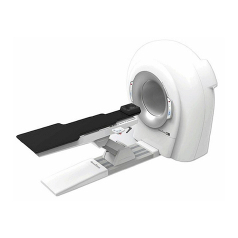
The system includes 3 main components:
Scanner Unit
Patient Table
Console Workstation
The console workstation is the computer that controls the scanner. In order to do that, the console runs a dedicated
software that provides the user interface to run and monitor the scanner unit.
Besides the software can be also used to perform the analysis of the acquired data.
The scanner is the main components of the system. It includes a radiological system, composed by the x-ray generator
and a flat panel and the electronics components / boards necessary for the machine's operation. These components are
mounted on a rotating structure driven by a motor.
During the scan, the gantry performs a rotation around the patient’s head taking maximum 360 images that are
acquired by the console.
4.1 Cables
The system includes the cables for the connection between main workstation and scanner. These two cables are:
Ethernet Cable(4 couples/26 AWG-FTP-Cat. 6)
CAN bus Cable (2 couples/24 AWG shielded)
The power supply cable is already connected inside the scanner, but needs to be connected to the main power of the
installation site by the installer.
ATTENTION:
The usage of accessories and cables different from the expected
ones can results in a decay of the electromagnetic compatibility
of the device!

Installing the system
______________________________________________________________________________________
NewTom 5G XL –Service Manual rev 4 Pag. 5-1
5 Installing the system
For a detailed description of the installation procedure, refer to the attached document “Installation Manual” code
97070044.

Console preparation
______________________________________________________________________________________
NewTom 5G XL –Service Manual rev 4 Pag. 6-1
6 Console preparation
The console workstation (or main workstation) is the computer that controls the scan machine.
Specific requirements, procedures and settings must be followed in order to prepare the computer to run the machine
and to obtain extreme performance.
The computer must comply with the specifications described in the “Workstation Setup” annex document.
For instructions about settings and installation on Main or Secondary Workstations (workstations that are not directly
connected with the machine) refer to the “Workstation Setup” annex document.

Networking and archive
______________________________________________________________________________________
NewTom 5G XL –Service Manual rev 4 Pag. 7-1
7 Networking and archive
The NNT software has been designed to provide the best functionality and performance when it is installed
in a LAN (Local Area Network) or workgroup.
Working in a workgroup means that different workstations have to share the same archives.
In the case of “NewTom VGi evo” these data include the documents created from the software (RawData,
Volumetric data, Studies, 2D images collections and Reports), the patients’ database and other files used by
the application.
For a complete guide of how to manage documents and archives, please refer to the specific document
97071196 “Software archive guide”
Other manuals for NEWTOM 5GXL
1
Table of contents
Other CEFLA Medical Equipment manuals

CEFLA
CEFLA NewTom 5G User manual

CEFLA
CEFLA MyRay Hyperion X9 User manual

CEFLA
CEFLA NewTom VGi evo User manual

CEFLA
CEFLA NewTom GiANO HR User manual

CEFLA
CEFLA NewTom 5G Series User manual

CEFLA
CEFLA NewTom 5G Series User manual

CEFLA
CEFLA NEWTOM 5GXL User manual

CEFLA
CEFLA NewTom 5G Vet User manual

CEFLA
CEFLA NewTom VGi evo User manual

CEFLA
CEFLA GiANO HR User manual