Steinberg Systems SBS-DM-1000USB User manual

SBS-DM-1000USB
BEDIENUNGSANLEITUNG
MULTIMETER BATTERIETESTER
USER MANUAL
MULTIMETER WITH BATTERY TESTER
INSTRUKCJA OBSŁUGI
MULTIMETR Z TESTEREM AKUMULATORA
NÁVOD K POUŽITÍ
MULTIMETR SE ZKOUŠEČKOU BATERIÍ
MANUEL D´UTILISATION
TESTEUR DE BATTERIE MULTIMÈTRE
ISTRUZIONI PER L’USO
MULTIMETRO TESTER BATTERIA
MANUAL DE INSTRUCCIONES
MULTÍMETRO CON COMPROBADOR DE BATERÍAS
DE | EN | PL | CZ | FR | IT | ES

3
09.07.2019
2
INHALT | CONTENT | TREŚĆ | OBSAH | CONTENU | CONTENUTO | CONTENIDO
Deutsch
English
Polski
Česky
Français
Italiano
Español
3
9
14
19
24
30
36
PRODUKTNAME MULTIMETER BATTERIETESTER
PRODUCT NAME MULTIMETER WITH BATTERY TESTER
NAZWA PRODUKTU MULTIMETR Z TESTEREM AKUMULATORA
NÁZEV VÝROBKU
NOM DU PRODUIT TESTEUR DE BATTERIE MULTIMÈTRE
NOME DEL PRODOTTO MULTIMETRO TESTER BATTERIA
NOMBRE DEL PRODUCTO
MODELL
SBS-DM-1000USB
PRODUCT MODEL
MODEL PRODUKTU
MODEL VÝROBKU
MODÈLE
MODELLO
MODELO
IMPORTEUR
EXPONDO POLSKA SP. Z O.O. SP. K.
IMPORTER
IMPORTER
DOVOZCE
IMPORTATEUR
IMPORTATORE
IMPORTADOR
ADRESSE VON IMPORTEUR
UL. NOWY KISIELIN-INNOWACYJNA 7, 66-002 ZIELONA GÓRA | POLAND, EU
IMPORTER ADDRESS
ADRES IMPORTERA
ADRESA DOVOZCE
ADRESSE DE L'IMPORTATEUR
INDIRIZZO DELL'IMPORTATORE
DIRECCIÓN DEL IMPORTADOR
Das Produkt erfüllt die geltenden
Sicherheitsnormen.
Gebrauchsanweisung beachten.
Recyclingprodukt.
Parameter Werte
Produktname Multimeter
Batterietester
Modell SBS-DM-1000USB
Batterietyp 9V(6F22)
Nennleistung [W] 3
Schutz vor Überspannungen CATIII 1000
Messbereich der Spannung
von Gleichstrom/
Wechselstrom
400mV~1000V/
4V~750V
Messbereich der Stromstärke
von Gleichstrom/
Wechselstrom
Messbereich des elektrischen
Widerstands / der elektrischen
Kapazität
51.2nF~100µF
Messbereich der Temperatur/
Arbeitszyklus
-20°C~1000°C/
5.12Hz~5.12MHz/
1%~99%
Schutzart IP IP20
Maximaler Ablesebereich 4000
Betriebstemperatur/ Relative
Arbeitsfeuchtigkeit [°C/%RH]
0~40/<85
Lagertemperatur/Relative
Lagerfeuchtigkei [°C/%RH]
-10~50/<85
Abmessungen [mm] 180x88x52
Gewicht [kg] 0,320
TECHNISCHE DATEN
Beschreibung des Handbuchs beziehen sich auf <Multimeter
Batterietester >. Benutzen Sie das Gerät nicht in Räumen mit
sehr hoher Luftfeuchtigkeit oder in unmittelbarer Nähe von
Wasserbehältern! Lassen Sie das Gerät nicht nass werden.
dürfen nicht verdeckt werden!
2.1. ELEKTRISCHE SICHERHEIT
a) Bei der Spannungsmessung muss sichergestellt
werden, dass der Regulator auf den entsprechenden
Frequenzbereich eingestellt ist.
b) Bei der Spannungsmessung von mehr als 50 V muss
besondere Vorsicht gewahrt werden.
c) Falls möglich, sollte vermieden werden, dass das
Gerät an „unter Spannung“ stehende Stromkreise
angeschlossen wird.
d) Vor Durchführung der Messungen: des Widerstandes,
des Dioden- oder Kontinuitätstests, des Kapazitäts-
oder Temperaturtests sollte sichergestellt werden,
dass der überprüfte Stromkreis nicht unter Spannung
steht.
e) Stellen Sie sicher, dass die richtige Funktion und der
richtige Messbereich ausgewählt sind, bevor Sie die
Messungen durchführen.
f) Bei Verwendung des Gerätes mit angeschlossenem
Stromwandler ist bei einem Stromausfall besondere
Vorsicht geboten.
g) Vor jedem Gebrauch sollte sichergestellt werden,
dass sich die Leitungen und Messungssensoren in
ohne Beschädigungen des Isoliermaterials.
h) Bevor der Batteriedeckel abgenommen wird, müssen
die Leitungen und Messungssensoren vom Gerät
abgenommen und der Regulator auf „OFF“ gestellt
werden.
i) Halten Sie bei der Messung die Messleitungen
ausschließlich an den isolierten Teilen fest.
j) Beachten Sie bei der Durchführung von Messungen
die allgemeinen Regeln und elektrotechnischen
Kenntnisse.
k) Ersetzen Sie abgenutzte Sicherungen durch eine
neue Sicherung des gleichen Typs und der gleichen
l) Ersetzen Sie defekte Messleitungen nur durch das
gleiche Modell oder durch die gleichen elektrischen
Parameter.
BEDIENUNGSANLEITUNG
1. ALLGEMEINE BESCHREIBUNG
Diese Anleitung ist als Hilfe für eine sichere und zuverlässige
Nutzung gedacht. Das Produkt wurde strikt nach den
technischen Vorgaben und unter Verwendung modernster
Technologien und Komponenten sowie unter Wahrung der
höchsten Qualitätsstandards entworfen und angefertigt.
VOR INBETRIEBNAHME MUSS DIE ANLEITUNG
GENAU DURCHGELESEN UND VERSTANDEN
WERDEN.
Für einen langen und zuverlässigen Betrieb des Geräts muss
auf die richtige Handhabung und Wartung entsprechend
den in dieser Anleitung angeführten Vorgaben geachtet
werden. Die in dieser Anleitung angegebenen technischen
behält sich das Recht vor, im Rahmen der Verbesserung der
Qualität Änderungen vorzunehmen.
ERLÄUTERUNG DER SYMBOLE
2. NUTZUNGSSICHERHEIT
ACHTUNG! Lesen Sie alle Sicherheitshinweise und
alle Anweisungen durch. Die Nichtbeachtung der
Warnungen und Anweisungen kann zu schweren
Verletzungen bis hin zum Tod führen.
Die originale Anweisung ist die deutschsprachige Fassung.
Sonstige Sprachfassungen sind Übersetzungen aus der
deutschen Sprache.
HINWEIS! In der vorliegenden Anleitung sind
Beispielbilder vorhanden, die von dem tatsächlichen
Aussehen das Produkt abweichen können.
DE
Nur zur Verwendung in geschlossenen Räumen.
ACHTUNG!, WARNUNG! oder HINWEIS!, um
auf bestimmte Umstände aufmerksam zu
machen (allgemeines Warnzeichen).

4 5
09.07.2019
m) Um Stromschläge und Beschädigungen an Geräten
zu vermeiden, dürfen die angegebenen Grenzwerte
für das Eingangssignal nicht überschritten werden.
n) Es ist verboten, die Position des Bereichsschalters
während der Messung zu ändern.
2.2. SICHERHEIT AM ARBEITSPLATZ
a) BenutzenSiedasGerätnichtinexplosionsgefährdeten
Bereichen, zum Beispiel in Gegenwart von
brennbaren Flüssigkeiten, Gasen oder Staub.
b) Im Falle eines Schadens oder einer Störung sollte
das Gerät sofort ausgeschaltet und dies einer
autorisierten Person gemeldet werden.
c) Wenn Sie nicht sicher sind, ob das Gerät
ordnungsgemäß funktioniert, wenden Sie sich an
den Service des Herstellers.
d) Reparaturen dürfen nur vom Service des Herstellers
durchgeführt werden. Führen Sie keine Reparaturen
auf eigene Faust durch!
e) Zum Löschen des Gerätes bei Brand oder Feuer, nur
Pulverfeuerlöscher oder Kohlendioxidlöscher (CO2)
verwenden.
f) Überprüfen Sie regelmäßig den Zustand der
Sicherheitsinformationsaufkleber. Falls die Aufkleber
unleserlich sind, sollten diese erneuert werden.
g) Bewahren Sie die Gebrauchsanleitung für
den weiteren Gebrauch auf. Sollte das Gerät
an Dritte weitergegeben werden, muss die
Gebrauchsanleitung mit ausgehändigt werden.
h) Verpackungselemente und kleine Montageteile
außerhalb der Reichweite von Kindern aufbewahren.
i) Im Laufe der Nutzung dieses Werkzeugs
übrigen Betriebsanweisungen richten.
2.3. PERSÖNLICHE SICHERHEIT
a) Es ist nicht gestattet, das Gerät im Zustand der
Drogen oder Medikamenten zu betreiben, wenn das
die Fähigkeit das Gerät zu bedienen, einschränkt.
b) Das Gerät darf nicht von Kindern oder Personen
mit eingeschränkten physischen, sensorischen und
geistigen Fähigkeiten oder ohne entsprechende
Erfahrung und entsprechendes Wissen bedient
werden. Dies ist nur unter Aufsicht einer für die
Sicherheit zuständigen Person und nach einer
Einweisung in die Bedienung der Maschine gestattet.
c) Das Gerät ist kein Spielzeug. Kinder sollten in der
Nähe des Geräts unter Aufsicht stehen, um Unfälle
zu vermeiden.
2.4. SICHERE ANWENDUNG DES GERÄTS
a) Nicht verwendete Werkzeuge sind außerhalb
der Reichweite von Kindern sowie von Personen
aufzubewahren, welche weder das Gerät noch die
Anleitung kennen. In den Händen unerfahrener
Personen können diese Geräte eine Gefahr darstellen.
b) Halten Sie das Gerät stets in einem einwandfreien
Zustand. Prüfen Sie vor jeder Inbetriebnahme, ob
am Gerät und seinen beweglichen Teilen Schäden
vorliegen (defekte Komponenten oder andere
Faktoren, die den sicheren Betrieb der Maschine
beeinträchtigen könnten). Im Falle eines Schadens
muss das Gerät vor Gebrauch in Reparatur gegeben
werden.
c) Halten Sie das Gerät außerhalb der Reichweite von
Kindern.
ACHTUNG! Obwohl das Gerät in Hinblick
auf Sicherheit entworfen wurde und über
Schutzmechanismen sowie zusätzlicher
Sicherheitselemente verfügt, besteht bei
der Bedienung eine geringe Unfall- oder
Verletzungsgefahr. Es wird empfohlen, bei der
Nutzung Vorsicht und Vernunft walten zu lassen..
3. NUTZUNGSBEDINGUNGEN
Das Gerät dient zur Messung von elektrischen Werten
sowie der Temperatur von ausgewählten Geräten und
Stromkreisen.
Für alle Schäden bei nicht sachgemäßer Verwendung
haftet allein der Betreiber.
3.1. GERÄTEBESCHREIBUNG
1. LCD-Display
2. SELECT Taste: Funktioniert im Bereich.
Testwahl: des Widerstands, der Dioden, der
Kontinuität des Stromkreises, der Kapazität, der
Spannungsbereiche, der Stromstärke, der Stromart,
des Temperaturbereichs und der Temperatureinheit
(indem die Taste gedrückt wird). Ausschalten der
und festgehalten wird).
3. HOLD-Taste: Den angezeigten Wert sperren /
freischalten.
4. PC-LINK Taste: Ein-/Ausschalten des PC Link Modus.
5. REL Taste: Aufzeichnung des momentan angezeigten
Werts im Speicher (Bezugswert). Der neue Wert
(relative Messung) stellt den Unterschied zwischen
dem Eingangswert (dem Wert der Messung) und
dem Bezugswert dar.
6. Hz/% Taste: Im Bereich „ACV/ACA“ oder „Hz“. Die
Frequenz (Hz) oder den Arbeitszyklus (%) zu wählen.
7. CDS Sensor
8. Drehknopf: Ausschalten des Geräts / Wahl der
Funktionen und des Messbereichs
9. Eingangsbuchse VHz
12. Eingangsbuchse: 20A
13. USB Port
3.2. VORBEREITUNG ZUR VERWENDUNG
VerwendenSiedasGerätnichtbeiUmgebungstemperaturen
über 40 °C sein und einer relativen Luftfeuchtigkeit über
80%. Achten Sie darauf, dass die Stromversorgung des
Gerätes den Angaben auf dem Produktschild entspricht.
Achtung! Die Grenzwerte des Überlastungsschutzes dürfen
nicht überschritten werden.
Detaillierte (elektrische) Parameter der Messungen:
• Wechselstromspannung (RMS)
Durchschnittliche Suche: Kalibrierung auf RMS
(Durchschnittsquadrat) der Sinuskurve.
Überlastungsschutz: 1.000V DC/750 V rms AC
• Gleichstromspannung
Überlastschutz: F 20 A/250 V Sicherung 20 A; bis zu 10
Sekunden ohne Sicherung, Sicherungen zurücksetzen PPTC
400 mA/250 V.
Bereich Genauigkeit
40mA
400mA
4A 1mA
20A 10mA
Bereich Genauigkeit Frequenz
4V
1mV
40~400Hz40V 10mV
400V 100mV
750V 1V 40~100Hz
d) Reparatur und Wartung von Geräten dürfen
Originalersatzteilen durchgeführt werden. Nur
so wird die Sicherheit während der Nutzung
gewährleistet.
e) Um die Funktionsfähigkeit des Gerätes zu
gewährleisten, dürfen die werksmäßig montierten
Abdeckungen oder Schrauben nicht entfernt werden.
f) Lassen Sie dieses Gerät während des Betriebs nicht
unbeaufsichtigt.
g) Das Gerät muss regelmäßig gereinigt werden, damit
sich nicht dauerhaft Schmutz festsetzt.
h) Lufteinlass und Luftauslass dürfen nicht verdeckt
werden.
i) Das Gerät ist kein Spielzeug. Reinigung und Wartung
dürfen nicht von Kindern ohne Aufsicht durch eine
erwachsene Person durchgeführt werden.
j) Es ist untersagt, in den Aufbau des Geräts
einzugreifen, um seine Parameter oder Konstruktion
zu ändern.
k) Geräte von Feuer – und Wärmequellen fernhalten
Durchschnittliche Suche: Kalibrierung auf RMS
(Durchschnittsquadrat) der Sinuskurve.
Überlastschutz: F 20 A/250 V Sicherung 20 A; bis zu 10
Sekunden ohne Sicherung, Sicherungen zurücksetzen PPTC
400 mA/250 V.
DE DE
18-28°C und einer Feuchtigkeit von 70% RH.).
• Gleichstromspannung
Bereich Genauigkeit
400mV
0,1mV
4V 1mV
40V 10mV
400V 100mV
1000V 1V
Überlastungsschutz: 1.000 V DC/750 V RMS AC
Bereich Genauigkeit Frequenz
40~400Hz
40mA
400mA
4A 1mA
20A 10mA
• Wechselstromspannung
• Widerstand
Bereich Genauigkeit
Überlastschutz: 250 V DC oder AC RMS
• Elektrische Kapazität
Bereich Genauigkeit
51,2nF 10pF
512nF
100pF
5,12µF 1nF
51,2µF 10nF
100µF 100nF
Überlastschutz: 250 V DC oder AC RMS
• Frequenz
Bereich Genauigkeit Frequenz
5,12Hz
0,001Hz
Sinusförmig 0,6
V RMS (5,12
MHz: 1,5 V
RMS)
51,2Hz 0,01Hz
512Hz 0,1Hz
5,12kHz 1Hz
51,2kHz 10Hz
512kHz 100Hz
5,12MHz 1kHz
Überlastschutz: 250 V DC oder AC RMS
ACHTUNG! Die Zeichnung von diesem
Bedienungsanleitung S. 42.

6 7
09.07.2019
4) Lesen Sie das Ergebnis auf der LCD-Anzeige ab.
• Achtung: Es muss sichergestellt werden, dass der
• Maximale Belastung: 250 V RMS < 10 s
Achtung:
es einige Sekunden dauern, bis ein stabiler Messwert
vorliegt.
• Wenn der Eingang nicht angeschlossen ist, d. h.
im Leerlauf, wird „OL“ angezeigt, wenn der Bereich
überschritten wird.
• Bei der Prüfung des Widerstands der Schaltung ist
darauf zu achten, dass die zu prüfende Schaltung
vollständig von der Stromversorgung getrennt ist
und alle Kondensatoren vollständig entladen sind.
3.3.1.3. DIODENTEST UND DURCHGANGSTEST DER
ELEKTRISCHEN SCHALTUNG
1) Verbinden Sie die schwarze Messleitung mit der
COM-Buchse und die rote Messleitung mit dem
Buchse „VHz
3) Um die Funktion zu ändern, drücken Sie die SELECT-
Taste, um eine Diode oder einen elektrischen
Durchgangstest auszuwählen.
4) Drücken Sie die Taste „SELECT “, um den Diodentest
auszuwählen.
5) Schließen Sie die schwarzen und roten Messleitungen
Diode an und lesen Sie den Spannungsabfallwert
von der Anzeige ab.
6) Drücken Sie „SELECT“, um den elektrischen
Durchgangstest auszuwählen.
7) Schließen Sie die Sonden an die zu prüfende
Schaltung an. Ein akustisches Signal wird
kontinuierlich ausgegeben, wenn der Widerstand
Hinweis: Achten Sie darauf, dass der geprüfte Stromkreis
nicht „unter Spannung“ steht.
Maximale Belastung: 250 V RMS<10 s
3.3.1.4. MESSUNG DER ELEKTRISCHEN KAPAZITÄT
1) Verbinden Sie das schwarze Messkabel mit der
Buchse „COM“ und das rote Messkabel mit der
Buchse „VHz
3) Verbinden Sie die Sonden mit dem zu testenden
Element.
4) Lesen Sie das Ergebnis auf der LCD-Anzeige ab.
Hinweis:
• Kondensatoren sollten vor der Messung entladen
werden.
• Bei der Prüfung von Komponenten mit großer
Kapazität dauert es länger, bis der Endwert angezeigt
wird (für den 100 uF-Bereich dauert es etwa 15
Sekunden).
• Wenn Sie Kondensatoren mit niedriger Kapazität
Sie dann die Messung fort, um die Genauigkeit der
Messung zu gewährleisten.
• Maximale Belastung: 250 V RMS<10 p.
Überlastschutz: Sicherungen werden auf PPTC 400 mA/250
V zurückgesetzt
• Batterietest
Bereich Beschreibung Testbedingungen
1,5V – 12V
Überlastschutz: 250 V DC oder AC RMS
3.3.1.5. FREQUENZMESSUNG
1) Verbinden Sie das schwarze Messkabel mit der
Buchse „COM“ und das rote Messkabel mit der
Buchse „VHz
2) Drehen Sie den Regler in den „Hz“-Bereich.
3) Stellen Sie den ausgewählten Test mit der Taste
„Hz/%“ ein: Hz (Frequenz) oder Duty (Arbeitszyklus).
4) Schließen Sie die Sonden zur Messung an eine
Quelle oder Last an.
5) Lesen Sie das Ergebnis auf der LCD-Anzeige ab.
3.3.1.6. TEMPERATURMESSUNG
2) Den schwarzen Messungsleitungsdraht an die „COM
3) Die Sonde an die ausgewählte
Temperaturmessungsstelle anschließen, um die
Messung durchzuführen.
4) Das Ergebnis auf dem LC-Display ablesen. Maximale
Belastung: 250 V RMS <10 s
A. Die Temperaturfunktion zeigt eine zufällige Zahl
an, um die Messung durchzuführen, muss das
Thermoelement an der Messstelle platziert werden.
B. Es ist untersagt, das Thermoelement gegen ein
anderes auszutauschen.
C. Hohe Temperaturen müssen mit einer speziellen
Sonde zur Überprüfung von hohen Temperaturen
gemessen werden.
3.3.1.7. GLEICHSTROM-(DC)-/WECHSELSTROM-(AC)-
MESSUNG
1) Verbinden Sie das schwarze Messkabel mit der
Buchse „COM“ und das rote Messkabel mit der
Buchse:
BATT“.
2) Stellen Sie den Regler auf die gewünschte Position
im Bereich „uA~“, „mA~“ oder „A~“, die
voreingestellte Funktion ist die Widerstandsmessung;
zum Ändern der Funktion, drücken Sie die SELECT-
Taste, um den Diodentest oder den elektrischen
Durchgangstest auszuwählen.
3) Stellen Sie den ausgewählten Test - DC oder AC - mit
der SELECT-Taste ein.
4) Schließen Sie die Sonden zur Messung an eine
Quelle oder Last an.
5) Lesen Sie das Ergebnis auf der LCD-Anzeige ab. Die
Polarität des roten Messkabels wird zusammen mit
dem DC-Messwert angezeigt.
3.3.1.8. BATTERIETEST
1) Verbinden Sie das schwarze Messkabel mit der
Buchse „COM“ und das rote Messkabel mit der
2) Bringen Sie den Regler in die Position „ “.
3) Schließen Sie die Sonden zur Messung an eine
Quelle oder Last an.
4) Lesen Sie das Ergebnis auf der LCD-Anzeige ab.
(Positive Messung beim Ladestrom: ca. 25 mA,
wenn kein Ladestrom vorhanden ist, ist die Messung
negativ.)
3.3.1.9. PC-LINK
Das Messgerät verfügt über eine serielle
Datenausgabefunktion. Es kann über eine USB-Schnittstelle
an einen Computer angeschlossen werden, so dass
Messdaten vom Computer erfasst, analysiert, verarbeitet
und gedruckt werden können. Bevor Sie diese Funktion
nutzen können, müssen Sie die PC-Link-Software und den
USB-Treiber auf Ihrem Computer installieren. (Hinweis: Die
Software ist auf Englisch.)
1) Installieren Sie die auf der CD enthaltene Software.
2) Nach dem Einschalten des Gerätes erscheint auf dem
Display die Funktion „PC-Link“, wenn sie erlischt,
sollte sie über die Taste „PC-Link“ aktiviert werden.
3) Verbinden Sie den Computer mit dem Gerät über das
USB-Kabel.
4) Starten Sie die Software „PC-Link“ auf Ihrem
SET PART. Wählen Sie dann den entsprechenden
COM-Port aus.
5) Wählen Sie die Standardabtastfrequenz oder eine
andere gewünschte Abtastrate. Drücken Sie die OK-
Taste, um die Einstellungen abzuschließen.
6) Drücken Sie Start in PC-LINK SOFT, um synchrone
Daten oder Diagramme in der Softwareschnittstelle
zu messen und anzuzeigen.
7) Um die Datenverbindungsfunktion zu deaktivieren,
drücken Sie die Taste „PC-LINK“, bis das Symbol „PC-
LINK“ auf dem Display verschwindet.
3.3.2. NUTZERANWEISUNGEN
• Eine Überschreitung des Anzeigebereichs hat zur
• Das Gerät schaltet sich automatisch nach 15 min Ruhe
aus. Die SELECT-Taste drücken, um das automatische
Ausschalten des Geräts zu desaktivieren.
• Erscheint das „ “ Symbol, muss die Batterie
ausgetauscht werden.
• Die Anzeige eines Dreieckes mit einem
Ausrufezeichen bedeutet:
eingeben werden kann; es ist möglich, eine
höhere Spannung anzuzeigen, aber es kann die
internen Schaltkreise des Gerätes beschädigen
oder einen elektrischen Schlag verursachen.
und der Maximalstrom von 20 A 20 A beträgt,
wird bei Überschreitung dieser Grenzwerte die
Sicherung zerstört. Da der 20 A-Bereich nicht
geschützt ist, sollte die Messzeit weniger als 1
Sekunde betragen, um eine Überhitzung des
Stromkreises zu vermeiden:
• Seien Sie vorsichtig bei der Messung von
Hochspannung, um einen möglichen elektrischen
Schlag zu vermeiden.
3.4. REINIGUNG UND WARTUNG
b) Lassen Sie nach jeder Reinigung alle Teile gut
trocknen, bevor das Gerät erneut verwendet wird.
c) Bewahren Sie das Gerät an einem trockenen, kühlen,
vor Feuchtigkeit und direkter Sonneneinstrahlung
geschütztem Ort auf.
d) Es ist verboten, das Gerät mit einem Wasserstrahl zu
besprühen oder in Wasser zu tauchen.
Vorbeugung vor Schäden sollte das Gerät regelmäßig
überprüft werden.
Bereich Beschreibung Testbedingungen
Darstellung der
annähernden
Diodenspannung.
Gleichstrom ca. 0,4 mA.
Gleichstromspannung
ca. 1,5V.
Die eingebaute
Klingel erzeugt
ein Signal, wenn
der Widerstand
schwächer ist als
Stromkreis 0,5V
Bereich Genauigkeit Frequenz
0,1%~99% Sinusförmig 0,6
V RMS >10kHz
Überlastschutz: 250 V DC oder AC RMS
• Temperatur (Sensor NiCr-NiSi)
Bereich Genauigkeit
°C -20~150°C 1°C
150~1000°C
Überlastschutz: Sicherungen werden auf PPTC 400 mA/250
V zurückgesetzt
• Diodentest und Signal bei einem unterbrochenen
Stromkreis
• Arbeitszyklus
3.3. ARBEIT MIT DEM GERÄT
3.3.1. MESSUNGSANLEITUNG
3.3.1.1. GLEICHSPANNUNG/WECHSELSPANNUNG
1) Den schwarzen Messungsleitungsdraht an die Buchse
die Buchse „VHz
2) Den Knopf auf „V~
drücken, um zum ausgewählten DC/AC-Test
überzugehen.
3) Die Sonden an die zur Durchführung der Messung
bestimmte Quelle oder Belastung anschließen.
4) Das Ergebnis auf dem LC-Display ablesen.
3.3.1.2. WIDERSTANDSMESSUNG
1) Verbinden Sie die schwarze Messleitung mit der
„COM“-Buchse und die rote Messleitung mit der
„VHz-Buchse
3) Schließen Sie die Sonden an die zu messende Quelle
oder Last an.
DE DE

8 9
09.07.2019
f) Benutzen Sie einen weichen Lappen zur Reinigung.
g) Entfernen Sie die Batterie aus dem Gerät, wenn es
über einen längeren Zeitraum nicht genutzt wird.
h) Schützen Sie das Gerät vor Feuchtigkeit. Wenn es
nass wird, wischen Sie es sofort trocken. Flüssigkeiten
können Mineralien enthalten, die elektronische
Schaltungen angreifen können.
i) Verwenden und lagern Sie das Gerät unter normalen
Temperaturbedingungen. Extreme Temperaturen
können die Lebensdauer des Geräts verkürzen, die
oder schmelzen.
j) Mit dem Gerät vorsichtig und feinfühlig umgehen.
Ein Herunterfallen des Gerätes kann die Leiterplatten
beschädigen und zu Fehlfunktionen des Gerätes
führen.
k) Das Gerät vor Staub und Schmutz schützen.
l) verwenden Sie nur neue Batterien der in den
technischen Daten angegebenen Größe und des
angegebenen Typs. Bevor die Batterien eingelegt
oder ausgetauscht werden, muss sichergestellt
werden, dass das Gerät an keinen externen
Stromkreis angeschlossen und dass der Regulator
auf „OFF“ gestellt ist und dass die Messleitungen von
den Klemmen getrennt sind.
m) Um einen elektrischen Schlag zu vermeiden, trennen
Sie die Messleitungen von den Messkreisen, bevor
Sie die Sicherung austauschen. Zum Schutz vor Feuer
verschlissene Sicherungen nur durch Sicherungen
F-200 mA / 250 V ersetzen.
n) Verwenden Sie das Gerät erst, wenn die hintere
Abdeckung ordnungsgemäß geschlossen und mit
der Schraube gesichert ist.
SICHERE ENTSORGUNG VON AKKUMULATOREN UND
BATTERIEN
Verwenden Sie für das Gerät 6F22 Batterien mit 9V.
Um die Batterie einzubauen, muss man:
2. Batterien mit entsprechenden technischen
Parametern hereinlegen.
3. Den Deckel der Batterie schließen und festschrauben.
Entnehmen Sie verbrauchte Batterien aus dem Gerät.
Führen Sie dazu die gleichen Schritte durch wie beim
Einsetzen der Batterien.
Entsorgen Sie leere Batterien bei den entsprechenden
Abgabestellen.
ENTSORGUNG GEBRAUCHTER GERÄTE
Dieses Produkt darf nicht über den normalen Hausmüll
entsorgt werden. Geben Sie das Gerät bei entsprechenden
Sammel- und Recyclinghöfen für Elektro- und
Elektronikgeräte ab. Überprüfen Sie das Symbol auf dem
Produkt, der Bedienungsanleitung und der Verpackung.
Die bei der Konstruktion des Gerätes verwendeten
recycelt werden. Mit der Entscheidung für das Recycling
leisten Sie einen wesentlichen Beitrag zum Schutz unserer
Umwelt. Wenden Sie sich an die örtlichen Behörden,
um Informationen über Ihre lokale Recyclinganlagen zu
erhalten.
standards.
Read instructions before use.
The product must be recycled.
Only use indoors.
Parameter description Parameter
value
Product name Multimeter with
battery tester
Model SBS-DM-1000USB
Battery type 9V(6F22)
Rated power [W] 3
Over Voltage Protection CATIII 1000
Measuring range of direct/
alternating current voltage
400mV~1000V/
4V~750V
Measuring range of direct/
alternating current amperage
Measuring range of electrical
resistance/capacitance
51.2nF~100µF
Measuring range of
temperature/frequency/duty
cycle
-20°C~1000°C/
5.12Hz~5.12MHz/
1%~99%
Protection rating IP IP20
Maximum reading 4000
Working temperature /
Relative working humidity
[°C/ %RH]
0~40/<85
Storage temperature/ Relative
storage humidity [°C/ %RH]
-10~50/<85
Dimensions [mm] 180x88x52
Weight [kg] 0,320
TECHNICAL DATA
instructions to refer to <Multimeter with battery tester>. Do
not use in very humid environments or in the direct vicinity
of water tanks. Prevent the device from getting wet. Risk of
electric shock! Do not cover the ventilation openings!
2.1. ELECTRICAL SAFETY
a) When measuring the voltage, make sure that the
knob is set to appropriate range.
b) Exercise caution when measuring voltage above DC
60V, AC 30V.
c) If possible, avoid connecting the device to live
circuits.
d) Before taking measurements of: resistance, diode or
continuity test, capacitance test or temperature test,
make sure that the tested circuit is not live.
e) Before taking the measurements, make sure that the
correct function and measuring range have been
selected.
f) Take special care in the event of a break in the circuit
when using the device in a system with an electric
current transformer connected to the terminals.
g) Before every use, make sure that the test leads and
probes are in good condition, e.g. the insulation is
undamaged.
h) Before disassembling the battery cover, disconnect
the test leads and probes from the device and set the
i) When measuring, make sure that you are holding
the insulated parts of the test leads.
j) Please observe general electrotechnical principles
and guidelines when taking measurements.
k) A blown fuse must be replaced with a new one of the
l) Replace damaged test leads only with the same
model or with the same electrical parameters.
m) To avoid electric shock and damage to the
instruments, do not exceed the limits of the input
signals.
n) Never change the position of the range switch
during the measurement.
2.2. SAFETY IN THE WORKPLACE
a) Do not use the device in a potentially explosive
environment, for example in the presence of
b) If you discover damage or irregular operation,
a supervisor without delay.
USER MANUAL
1. GENERAL DESCRIPTION
The user manual is designed to assist in the safe and
trouble-free use of the device. The product is designed
and manufactured in accordance with strict technical
guidelines, using state-of-the-art technologies and
components. Additionally, it is produced in compliance
with the most stringent quality standards.
DO NOT USE THE DEVICE UNLESS YOU HAVE
THOROUGHLY READ AND UNDERSTOOD THIS
USER MANUAL.
To increase the product life of the device and to ensure
trouble-free operation, use it in accordance with this user
manual and regularly perform maintenance tasks. The
up to date. The manufacturer reserves the right to make
changes associated with quality improvement.
LEGEND
2. USAGE SAFETY
ATTENTION! Read all safety warnings and all
instructions. Failure to follow the warnings and
instructions may result in serious injury or even
death.
The original operation manual is written in German. Other
language versions are translations from the German.
PLEASE NOTE! Drawings in this manual are for
illustration purposes only and in some details may
WARNING! or CAUTION! or REMEMBER!
Applicable to the given situation. (general
warning sign)
DE EN

10 11
09.07.2019
Range Description Test conditions
Displaying
approximate
diode voltage
Constant current about
0,4 mA.
DC voltage around 1,5V.
• AC voltage
Average detection: calibrated to RMS (average square) of
a sine wave.
Overload protection: 1000V DC/750Vrms AC
• Constant current
Overload protection: F 20A / 250V 20A fuse; up to 10
seconds without a fuse, resettable PPTC 400mA / 250V
fuses.
• Intensity of alternating current
Range Accuracy Resolution
40mA
400mA
4A 1mA
20A 10mA
• Resistance
Range Accuracy Resolution Frequency
4V
1mV
40~400Hz40V 10mV
400V 100mV
750V 1V 40~100Hz
Range Accuracy Resolution
Overload protection: 250V DC or AC rms
• Electrical capacity
Average detection: calibrated to RMS (root mean square)
of a sine wave.
Overload protection: F 20A / 250V 20A fuse; up to 10
seconds without a fuse, resettable PPTC 400mA / 250V
fuses.
• DC voltage
Range Accuracy Resolution
400mV
0,1mV
4V 1mV
40V 10mV
400V 100mV
1000V 1V
Overload protection: 1000V DC/750Vrms AC
Range Accuracy Resolution Frequency
40~400Hz
40mA
400mA
4A 1mA
20A 10mA
Range Accuracy Resolution
51,2nF 10pF
512nF
100pF
5,12µF 1nF
51,2µF 10nF
100µF 100nF
Overload protection: 250V DC or AC rms
• Frequency
Range Accuracy Resolution Sensitivity
5,12Hz
0,001Hz
Sinusoid
0.6 V rms
(5,12 MHz:
1,5 V rms)
51,2Hz 0,01Hz
512Hz 0,1Hz
5,12kHz 1Hz
51,2kHz 10Hz
512kHz 100Hz
5,12MHz 1kHz
Overload protection: 250V DC or AC rms
• Work cycle
Range Accuracy Sensitivity Frequency
0,1%~99% Sinusoid
0.6 V rms >10kHz
Overload protection: 250V DC or AC rms
• Temperature (NiCr-NiSi sensor)
Range Accuracy Resolution
°C -20~150°C 1°C
150~1000°C
Overload protection: resettable PPTC 400mA / 250V fuses.
• Diode test and signal of interrupted circuit
c) If there are any doubts as to the correct operation
of the device, contact the manufacturer's support
service.
d) Only the manufacturer's service point may repair the
device. Do not attempt any repairs independently!
(CO2
electrical devices) to put it out.
f) Regularly inspect the condition of the safety labels. If
the labels are illegible, they must be replaced.
g) Please keep this manual available for future
reference. If this device is passed on to a third party,
the manual must be passed on with it.
h) Keep packaging elements and small assembly parts
in a place not available to children.
i) If this device is used together with another
equipment, the remaining instructions for use shall
also be followed.
2.3. PERSONAL SAFETY
a) Do not use the device when tired, ill or under the
device.
b) The device is not designed to be handled by persons
(including children) with limited mental and sensory
functions or persons lacking relevant experience
and/or knowledge unless they are supervised by
a person responsible for their safety or they have
received instruction on how to operate the device.
c) The device is not a toy. Children must be supervised
to ensure that they do not play with the device.
2.4. SAFE DEVICE USE
a) When not in use, store in a safe place, away from
children and people not familiar with the device who
have not read the user manual. The device may pose
a hazard in the hands of inexperienced users.
b) Keep the device in perfect technical condition.
Before each use check for general damage and
especially check for cracked parts or elements and
for any other conditions which may impact the safe
operation of the device. If damage is discovered,
hand over the device for repair before use.
c) Keep the device out of the reach of children.
d) Device repair or maintenance should be carried out
This will ensure safe use.
e) To ensure the operational integrity of the device, do
any screws.
f) Do not leave this appliance unattended while it is in
use.
g) Clean the device regularly to prevent stubborn grime
from accumulating.
h) Do not cover the air intake and outlet.
i) The device is not a toy. Cleaning and maintenance
may not be carried out by children without
supervision by an adult person.
j) It is forbidden to interfere with the structure of
the device in order to change its parameters or
construction.
ATTENTION! Despite the safe design of the device
and its protective features, and despite the use of
additional elements protecting the operator, there is
still a slight risk of accident or injury when using the
device. Stay alert and use common sense when using
the device.
3. USE GUIDELINES
The device measures the electrical values and the
temperatures of selected devices and electrical circuits.
The user is liable for any damage resulting from
unintended use of the device.
3.1. DEVICE DESCRIPTION
1. LCD display.
selection: Resistance, diodes, circuit continuity,
capacitance, and the measuring range: voltage,
amperage, the type of current, temperature ranges
button).
3. HOLD button/ Lock/unlock the displayed value.
5. REL button: Saving the currently displayed value
in the memory (reference value). The new value
input value (measurement) and the reference value.
(%) measurement
7. CDS sensor
and measuring range.
9. Input jack: VHz
12. Input jack: 20A
13. USB port
3.2. PREPARING FOR USE
The temperature of environment must not be higher than
40°C and the relative humidity should be less than 80%.
The power cord connected to the appliance must be
correspond to the technical details on the product label.
Please note: The limit values for overload protection must
not be exceeded.
Detailed (electrical) measurement parameters:
ATTENTION! This product‘s view can be found on
the last pages of the operating instructions (pp. 42).
of last digits (at temperature: 18-28°C and humidity
EN EN

12 13
09.07.2019
f) Use a soft cloth for cleaning.
g) Do not leave the battery in the device if it will not be
used for a longer period of time.
h) Protect the device against moisture. If it is wet, wipe
it dry immediately. Liquids may contain minerals
which can corrode electronic circuits.
i) Use and store the device in standard temperature
conditions. Extreme temperatures can shorten the
life of the device, damage the batteries and deform
or melt plastic parts.
j) Handle the device with care. Dropping it may damage
printed circuit boards and cause malfunctioning.
k) Protect the device from dust and dirt.
l) Use only new batteries of the size and type indicated
replacing the batteries, make sure that the device is
not connected to an external circuit, that the control
disconnected from the terminals.
m) To avoid electric shock, disconnect the test leads
from the measuring circuits before replacing the
fuse.
whose rating is F-200mA / 250V.
n) Do not use the device until the back cover is properly
closed and secured with a screw.
SAFE REMOVAL OF BATTERIES AND RECHARGEABLE
BATTERIES
9V (6F22) batteries are installed in the devices.
Inserting a battery:
1. Open the battery cover on the back of the device
with a screwdriver.
2. Insert the batteries that correspond to the technical
parameters.
3. Close and screw on the battery cover.
Remove used batteries from the device using the same
procedure by which you installed them.
Recycle batteries with the appropriate organisation or
company.
DISPOSING OF USED DEVICES
Do not dispose of this device in municipal waste systems.
Hand it over to an electric and electrical device recycling
and collection point. Check the symbol on the product,
instruction manual and packaging. The plastics used
to construct the device can be recycled in accordance
with their markings. By choosing to recycle you are
environment. Contact local authorities for information on
your local recycling facility.
3.3.1.8. BATTERY TEST
3) Connect the probes to the source or load to make
the measurement.
4) Read the result from the LCD display. (The
measurement is positive when the charging current
is approx. 25 mA. When there is no charging current,
the measurement is negative).
3.3.1.9. PC-LINK
The meter has the function of serial data output. It can
be connected to a computer via a USB interface thanks
to which measurement data can be registered, analysed,
processed and printed by the computer. Before using this
function, install the PC-Link software and USB driver on
your computer. (Note: the software is in English.)
1) Install the software included on the CD.
will appear on the display. If it goes out, it should be
3) Connect the computer to the device using a USB
cable.
the appropriate COM port.
5) Select the default sample rate or select another
desired sample rate. Press the OK button to complete
the settings.
6) Press Start in PC-LINK SOFT to measure and display
synchronized data or graphs in the software
interface.
disappears from the display.
3.3.2. DIRECTIONS FOR USE
will be displayed.
of inactivity. Press SELECT button to deactivate the
device automatic shutdown.
• A displayed triangle with an exclamation mark
means that
applied. A higher voltage can be shown but it
can destroy the internal circuits of the device or
cause an electric shock.
maximum for 20A is 20A. Exceeding these limits
will destroy the fuse. Since the 20A range is not
protected, the measurement time should be
less than 1 second to prevent the circuit from
overheating.
• Be careful when measuring high voltages because of
the risk of electric shock.
3.4. CLEANING AND MAINTENANCE
a) Use only non-corrosive cleaners to clean the surface.
b) After cleaning the device, all parts should be dried
completely before using it again.
c) Store the unit in a dry, cool place, free from moisture
and direct exposure to sunlight.
d) Do not spray the device with a water jet or submerge
it in water.
e) The device must be regularly inspected to check its
3.3. DEVICE USE
3.3.1. MEASUREMENT INSTRUCTIONS
3.3.1.1. DC/AC VOLTAGE
socket.
~
the selected DC/AC test
3) Connect the probes to the source or load to be
measured.
4) Read the result from the LCD display.
3.3.1.2. RESISTANCE MEASUREMENT
3) Connect the probes to the source or load to be
measured.
4) Read the result from the LCD display.
Please note: Make sure that the circuit under test is not live.
Maximum load: 250 V rms <10 s
Note:
may take a few seconds to obtain.
• When the input is not connected, i.e. the circuit is
is exceeded.
• When testing a circuit resistance, make sure that the
circuit under test is completely disconnected from
the power supply and that all capacitors have been
completely discharged.
3.3.1.3. THE DIODE TEST AND ELECTRICAL CIRCUIT
CONTINUITY TEST
3) To change the function, press the SELECT button to
select the diode test or the continuity test.
5) Connect the black and red test leads to the cathode
voltage drop from the display.
continuity test.
7) Connect the probes to the circuit to be tested. The
acoustic signal will be continuous if the resistance is
Range Description Test conditions
The built-in buzzer
sounds when the
resistance is less than
Open circuit voltage
around 0,5V
Overload protection: resettable PPTC 400mA / 250V fuses.
• Battery test
Range Accuracy Test conditions
1,5V – 12V
Overload protection: 250V DC or AC rms
Note:
Make sure that the circuit under test is not energized.
Maximum load: 250 V rms <10 s
3.3.1.4. THE ELECTRICAL CAPACITY MEASUREMENT
3) Connect the probes to the part being tested.
4) Read the result from the LCD display.
Note:
• The capacitors should be discharged before
measurement.
• When testing high-capacity components, the
is shown (for the 100uF range it will take about 15
seconds).
• Maximum load: 250 V rms <10 s.
3.3.1.5. FREQUENCY MEASUREMENT
(frequency) or Duty (duty cycle).
4) Connect the probes to the source or load to make
the measurement.
5) Read the result from the LCD display.
3.3.1.6. TEMPERATURE MEASUREMENT
3) Connect the probe to the selected temperature
measurement location.
4) Read the result from the LCD display.
Maximum load: 250 V rms <10 s
A. The temperature function indicates a random
number. In order to take a measurement, place the
thermocouple at the measuring point
one.
C. High temperatures should be measured using
a probe designed to test high temperatures
3.3.1.7. DC / AC MEASUREMENT
the red test lead to the following jacks:
•
•
~~~
measurement. To change the function, press the
SELECT button to choose the diode test or electrical
circuit continuity test.
3) Use the SELECT button to choose the DC or AC test.
4) Connect the probes to the source or load to make
the measurement.
5) Read the result from the LCD display. Together with
the DC measurement value, the polarization of the
red test lead will be indicated.
EN EN

14 15
09.07.2019
b) W razie stwierdzenia uszkodzenia lub
uprawnionej.
samodzielnie!
2).
h) Elementy opakowania oraz drobne elementy
nadzoru.
UWAGA!
elektrycznych.
Odpowiedzialność za wszelkie szkody powstałe
w wyniku użytkowania niezgodnego z przeznaczeniem
ponosi użytkownik.
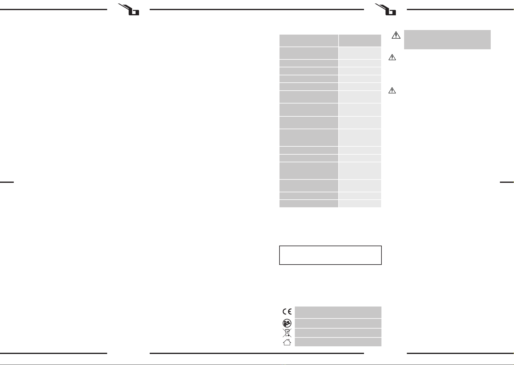
3. Przycisk D.HOLD: Blokowanie/ odblokowywanie
Link
7. Czujnik CDS
i zakresu pomiaru
13. Port USB
3.2. PRZYGOTOWANIE DO PRACY
UWAGA!
instrukcji na stronie 42.
celem zmiany jego parametrów lub budowy.
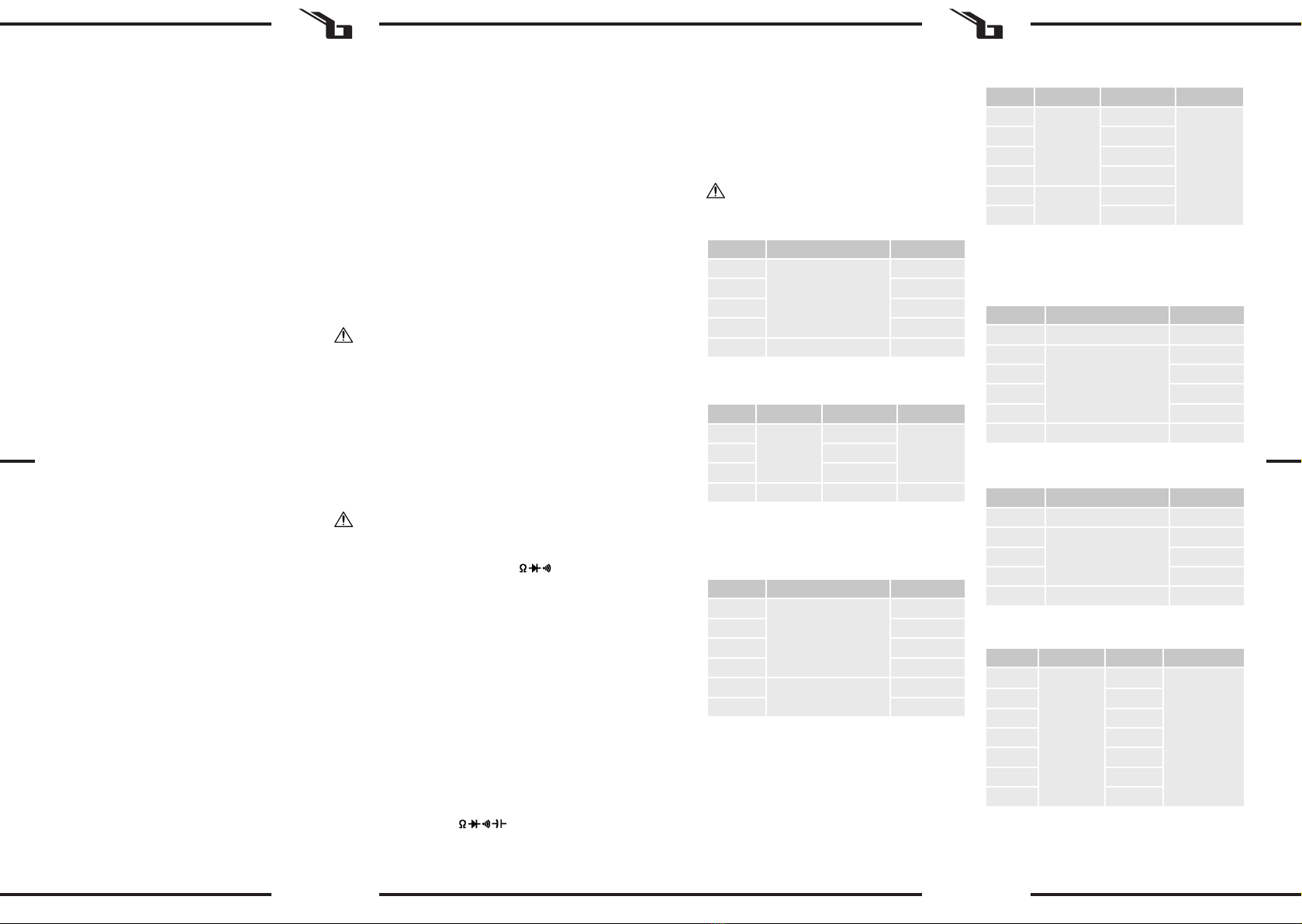
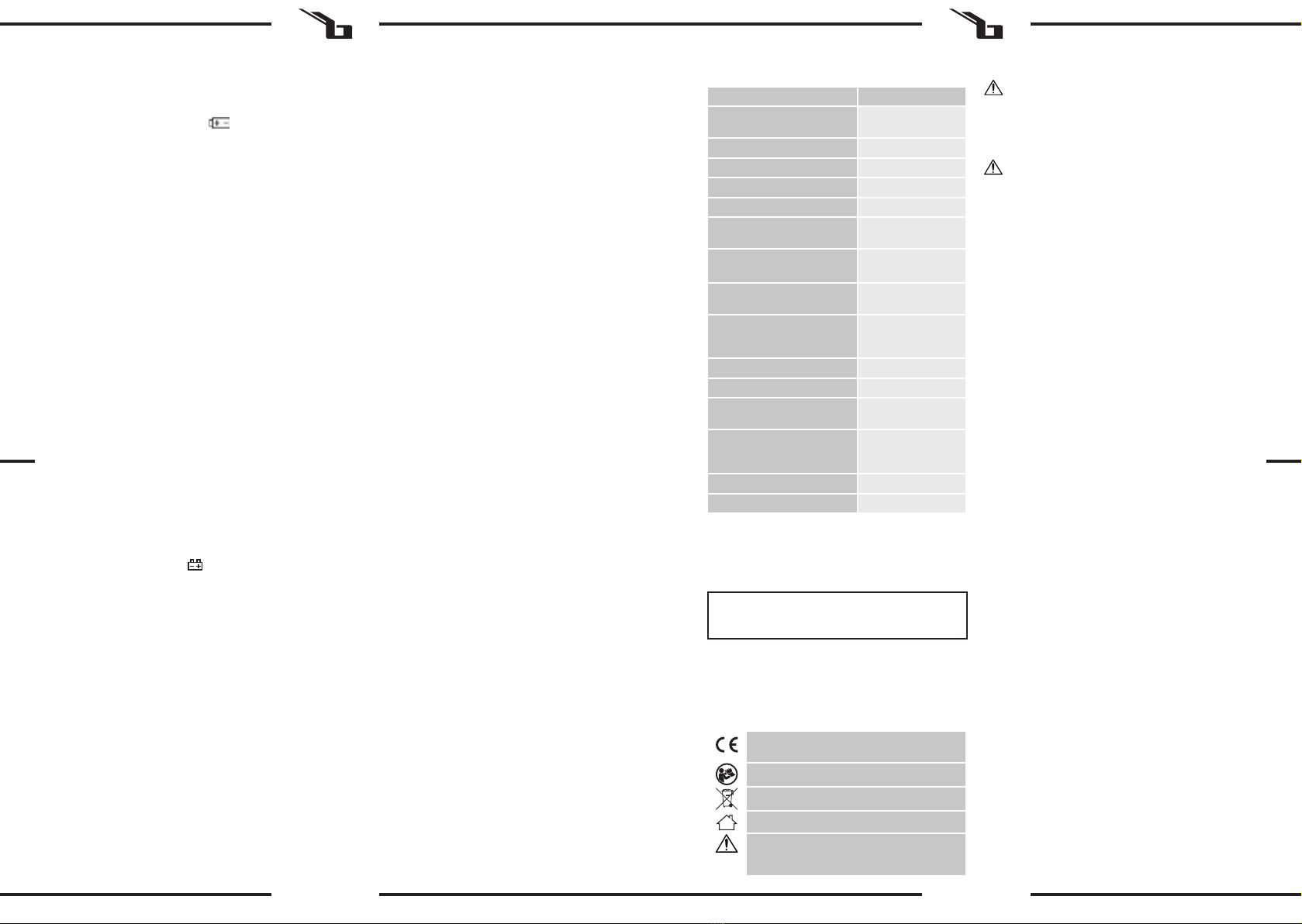
Opis parametru
Nazwa produktu Multimetr z testerem
akumulatora
Model SBS-DM-1000USB
Typ baterii 9V(6F22)
Moc znamionowa [W] 3
CATIII 1000
400mV~1000V/
4V~750V
51.2nF~100µF
Zakres pomiaru temperatury/
-20°C~1000°C/
5.12Hz~5.12MHz/
1%~99%
Klasa ochrony IP IP20
Maksymalny odczyt 4000
Temperatura pracy/
[°C/%RH]
0~40/<85
-10~50/<85
Wymiary [mm] 180x88x52
0,320
DANE TECHNICZNE
jest ustawione na odpowiedni zakres.
d) Przed wykonaniem pomiarów: rezystancji, testu
technicznym np. bez uszkodzenia izolacji.
i) Podczas dokonywania pomiaru przewody
do ogólnych zasad i wiedzy elektrotechnicznej.
na ten sam model lub o tych samych parametrach
elektrycznych.
w trakcie dokonywanego pomiaru.
1. OGÓLNY OPIS
Instrukcja przeznaczona jest do pomocy w bezpiecznym
PRZED PRZYSTĄPIENIEM DO PRACY NALEŻY
DOKŁADNIE PRZECZYTAĆ I ZROZUMIEĆ NINIEJSZĄ
INSTRUKCJĘ.
zgodnie ze wskazówkami zawartymi w tej instrukcji. Dane
aktualne. Producent zastrzega sobie prawo dokonywania
2.
UWAGA!
niemieckiego.
UWAGA!
ostrzegawczy).
PL PL

16 17
09.07.2019
3.3.1. INSTRUKCJA POMIARU
„VHz
~
przeznaczonego do wykonania pomiaru.
3.3.1.2. POMIAR REZYSTANCJI
„VHz
przeznaczonego do wykonania pomiaru.
•
Uwaga:
przekroczenia zakresu.
3.3.1
ELEKTRYCZNEGO
„VHz
elektrycznego.
elektrycznego.
Zakres Opis Warunki testu
w obwodzie
PPTC 400mA/250V
• Test baterii
Zakres Warunki testu
1,5V – 12V
•
<10 s
Uwaga:
pomiarem.
wykonania pomiaru.
3.3.1.6. POMIAR TEMPERATURY
temperatury w celu wykonania pomiaru.
w punkcie pomiarowym
sondy przeznaczonej do testowania wysokich
temperatur.
(DC)/
ZMIENNEGO (AC)
~ ~ ~
wykonania pomiaru.
pomiaru DC wskazana zostanie polaryzacja
czerwonego przewodu pomiarowego.
Zakres Opis Warunki testu
•
kwadratowa) fali sinusoidalnej. Ochrona przed
•
20A; do 10 sekund bez bezpiecznika, bezpieczniki
resetowane PPTC 400mA/250V.
•
Zakres
40mA
400mA
4A 1mA
20A 10mA
• Opór
Zakres
4V
1mV
40~400Hz40V 10mV
400V 100mV
750V 1V 40~100Hz
Zakres
•
kwadratowa) fali sinusoidalnej. Ochrona przed
sekund bez bezpiecznika, bezpieczniki resetowane PPTC
400mA/250V.
•
Zakres
400mV
0,1mV
4V 1mV
40V 10mV
400V 100mV
1000V 1V
Zakres
40~400Hz
40mA
400mA
4A 1mA
20A 10mA
Zakres
51,2nF 10pF
512nF
100pF
5,12µF 1nF
51,2µF 10nF
100µF 100nF
•
Zakres
5,12Hz
0,001Hz
Sinusoida
0,6 V rms
(5,12 MHz:
1,5 V rms)
51,2Hz 0,01Hz
512Hz 0,1Hz
5,12kHz 1Hz
51,2kHz 10Hz
512kHz 100Hz
5,12MHz 1kHz
• Cykl pracy
Zakres
0,1%~99% Sinusoida
0,6 V rms >10kHz
• Temperatura (czujnik NiCr-NiSi)
Zakres
°C -20~150°C 1°C
150~1000°C
PPTC 400mA/250V.
•
PL PL

18 19
09.07.2019
obwodów elektronicznych.
warunkach temperaturowych. Ekstremalne temperatury
i typie wskazanym w parametrach technicznych.
tylko na bezpiecznik o parametrach F-200mA / 250V.
AKUMULATORÓW I BATERII.
technicznym.
niniejszegoproduktupoprzeznormalneodpadykomunalne,
3.3.1.8. TEST BATERII
wykonania pomiaru.
3.3.1.9. PC-LINK
analizowane, przetwarzane i drukowane przez komputer.
komputerze oprogramowanie PC-Link i sterownik USB.
USB.
w interfejsie oprogramowania.
• Przekroczenie zakresu wskazania spowoduje
200mA, a maksymalny dla 10A wynosi 10A,
przekroczenie tych limitów zniszczy bezpiecznik.
zapobiec przegrzaniu obwodu.
3.4. CZYSZCZENIE I KONSERWACJA
Recyklovatelný výrobek.
Popis parametru Hodnota parametru
Multimetr se
Model SBS-DM-1000USB
Typ baterie 9V(6F22)
Jmenovitý výkon [W] 3
CATIII 1000
400mV~1000V/
4V~750V
51.2nF~100µF
-20°C~1000°C/
5.12Hz~5.12MHz/
1%~99%
IP20
4000
0~40/<85
%RH]
-10~50/<85
180x88x52
Hmotnost [kg] 0,320
TECHNICKÉ ÚDAJE
otvory!
elektrotechniky.
model nebo za model se stejnými elektrickými
parametry.
nebo prachu
2).
1. VŠEOBECNÝ POPIS
.
PŘED ZAHÁJENÍM PRÁCE SI DŮKLADNĚ PŘEČTĚTE
TENTO NÁVOD A UJISTĚTE SE, ŽE JSTE POCHOPILI
VŠECHNY POKYNY.
2.
POZNÁMKA!
POZOR!
PL CZ

20 21
09.07.2019
Rozsah Popis
0,4 mA.
proudu cca 1,5V.
mA/250 V
•
•
mA/250 V
•
Rozsah
40mA
400mA
4A 1mA
20A 10mA
• Odpor
Rozsah Frekvence
4V
1mV
40~400Hz40V 10mV
400V 100mV
750V 1V 40~100Hz
Rozsah
•
mA/250 V
•
Rozsah
400mV
0,1mV
4V 1mV
40V 10mV
400V 100mV
1000V 1V
Rozsah Frekvence
40~400Hz
40mA
400mA
4A 1mA
20A 10mA
Rozsah
51,2nF 10pF
512nF
100pF
5,12µF 1nF
51,2µF 10nF
100µF 100nF
• Frekvence
Rozsah Citlivost
5,12Hz
0,001Hz
Sinusoida
0,6 Vrms
(5,12 MHz:
1,5 V rms)
51,2Hz 0,01Hz
512Hz 0,1Hz
5,12kHz 1Hz
51,2kHz 10Hz
512kHz 100Hz
5,12MHz 1kHz
•
Rozsah Citlivost Frekvence
0,1%~99% Sinusoida
0,6 V rms >10kHz
• Teplota (senzor NiCr-NiSi)
Rozsah
°C -20~150°C 1°C
150~1000°C
mA/250 V
•
obsluhovat.
parametry nebo konstrukci.
POZNÁMKA!
Odpovědnost za veškeré škody vzniklé v důsledku
použití zařízení v rozporu s určením nese uživatel.
1. LCD displej
. Volba
testu: odporu, diod, spojitosti obvodu, kapacity,
hodnoty
7. CDS senzor
13. USB port
POZNÁMKA!
CZ CZ

22 23
09.07.2019
odpojeny od svorek.
pojistky pouze za pojistku s parametry F 200 mA/250
V.
odevzdat.
LINK SOFT.
zmizel z displeje.
elektrickým proudem.
svitu.
.
~
“.
“.
Pozor:
3.3.1.3. TEST DIODY A KONTINUITY ELEKTRICKÉHO
OBVODU
“.
“.
“.
“.
• Test baterii
Rozsah
testu
1,5V – 12V
Pozor:
“.
3
PROUDU (DC)(AC)
• pro rozsah od 2 A do 20 A: „20 A“,
~“, „m~“
nebo „A~
obvodu.
AC.
“.
3.3.1.9. PC-LINK
CZ CZ

24 25
09.07.2019
en vigueur.
Respectez les consignes du manuel.
Description des paramètres Valeur des
paramètres
Nom du produit Testeur de batterie
multimètre
Modèle SBS-DM-1000USB
Type de batterie 9V(6F22)
Puissance nominale [W] 3
Protection contre les
surtensions
CATIII 1000
Plage de mesure de la tension
du courant continu/courant
alternatif
400mV~1000V/
4V~750V
du courant continu/courant
alternatif
Plage de mesure de
51.2nF~100µF
Plage de mesure de la
rapport cyclique
-20°C~1000°C/
5.12Hz~5.12MHz/
1%~99%
Classe de protection IP IP20
Lecture maximale 4000
relative de travail [°C/ RH]
0~40/<85
[°C/ %RH]
-10~50/<85
Dimensions [mm] 180x88x52
Poids [kg] 0,320
DÉTAILS TECHNIQUES
Les notions d'«appareil», de «machine» et de «produit»
se rapportent à/au < Testeur de batterie multimètre >.
2.1. SÉCURITÉ ÉLECTRIQUE
a) Lors de la mesure de la tension, assurez-vous que le
b) Faites particulièrement attention lorsque vous
circuits sous tension.
e) Avant de prendre des mesures, assurez-vous que la
f) Faites particulièrement attention en cas de rupture
du circuit lors de l'utilisation de l'appareil dans un
aux pinces.
g) Avant chaque utilisation, assurez-vous que les
dommage.
position « OFF ».
i) Lors de la mesure, tenez les câbles par les parties
MANUEL D´UTILISATION
1. DESCRIPTION GÉNÉRALE
techniques applicables et en utilisant les technologies et
composants les plus modernes. Il est conforme aux normes
LISEZ ATTENTIVEMENT LE PRÉSENT MANUEL ET
ASSUREZ-VOUS DE BIEN LE COMPRENDRE AVANT
LA PREMIÈRE UTILISATION.
contenues dans ce document sont à jour. Le fabricant se
SYMBOLES
2. CONSIGNES DE SÉCURITÉ
ATTENTION! Veuillez lire attentivement toutes les
non-respect des avertissements et des consignes
la mort.
allemand. Toutes les autres versions sont des traductions
de l'allemand.
REMARQUE! Les illustrations contenues dans le
ATTENTION !, AVERTISSEMENT ! et REMARQUE
attirent l'attention sur des circonstances
n) Il est interdit de changer la position du commutateur
de plage pendant la mesure.
2.2. SÉCURITÉ AU POSTE DE TRAVAIL
a) N'utilisez pas l'appareil dans les zones à risque
b) En cas de dommages ou de mauvais fonctionnement,
c) En cas d’incertitude quant au fonctionnement correct
de l’appareil, contactez le service client du fabricant.
e) En cas de feu ou d’incendie, utilisez uniquement des
extincteurs à poudre ou au dioxyde de carbone (CO2)
illisibles, remplacez-les.
rapportant à ces outils.
2.3. SÉCURITÉ DES PERSONNES
l'appareil.
trouvent sous la supervision et la protection d'une
personne responsable ou qu'une telle personne leur
l'utilisation de l’appareil.
c) Cet appareil n'est pas un jouet. Les enfants doivent
ne jouent pas avec l’appareil.
2.4. UTILISATION SÉCURITAIRE DE L'APPAREIL
a) Les outils qui ne sont pas en cours d'utilisation
personnes qui ne connaissent ni l'appareil, ni le
manuel d'utilisation s'y rapportant. Entre les mains
ATTENTION!
comporte des dispositifs de protection, ainsi que des
pas possible d’exclure entièrement tout risque de
blessure lors de son utilisation. Nous recommandons
de faire preuve de prudence et de bon sens lorsque
vous utilisez l’appareil.
3. CONDITIONS D’UTILISATION
L’utilisateur porte l’entière responsabilité pour
l’ensemble des dommages attribuables à un usage
inapproprié.
3.1. DESCRIPTION DE L'APPAREIL
1. Écran LCD.
2. Bouton SELECT : Fonctionne dans la plage
5. Bouton REL : Enregistre la valeur actuellement
6. Bouton Hz /% : Dans la plage « ACV / ACA » ou « Hz
(%).
7. Capteur CDS
fonction et la plage de mesure.
13. Port USB
ATTENTION! Le plan de ce produit se trouve à la
dernière page du manuel d‘utilisation, p. 42
l'aide de pièces de rechange d'origine. Cela garantit
f) Ne laissez pas l’appareil fonctionner sans surveillance.
l’encrassement.
i) Cet appareil n'est pas un jouet. Le nettoyage et
enfants, à moins qu’ils se trouvent sous la supervision
d’un adulte responsable.
les paramètres ou la construction.
chaleur.
FR FR

26 27
09.07.2019
Protection contre les surcharges : fusibles PPTC
• Test de batterie
Plage Description Conditions de
test
1,5V – 12V
Protection contre les surcharges : 250V DC ou AC rms
Plage Description Conditions de test
la tension
approximative
de la diode..
Courant continu environ
0,4 mA.
Tension du courant continu
environ 1,5V.
La sonnerie
lorsque la
Tension de circuit ouvert
environ 0,5V
• Tension du courant alternatif
moyenne) d'une onde sinusoïdale.
Protection contre les surcharges : 1000 V CC/750 Vrms CA
•
Protection contre les surcharges : Fusible F 20A / 250V 20A;
jusqu’à 10 secondes sans fusible, fusibles PPTC 400mA /
Plage
40mA
400mA
4A 1mA
20A 10mA
•
Plage
4V
1mV
40~400Hz40V 10mV
400V 100mV
750V 1V 40~100Hz
Plage
Protection contre les surcharges : 250V DC ou AC rms
•
moyenne) d'une onde sinusoïdale.
Protection contre les surcharges : Fusible F 20A / 250V 20A;
jusqu’à 10 secondes sans fusible, fusibles PPTC 400mA /
• Tension du courant continu
Plage
400mV
0,1mV
4V 1mV
40V 10mV
400V 100mV
1000V 1V
Protection contre les surcharges : 1 000 V CC/750 Vrms CA
mV.
Plage
40~400Hz
40mA
400mA
4A 1mA
20A 10mA
Plage
51,2nF 10pF
512nF
100pF
5,12µF 1nF
51,2µF 10nF
100µF 100nF
Protection contre les surcharges : 250V DC ou AC rms
•
Plage
5,12Hz
0,001Hz
Sinusoïde
0,6 V rms
(5,12 MHz :
1,5 V rms)
51,2Hz 0,01Hz
512Hz 0,1Hz
5,12kHz 1Hz
51,2kHz 10Hz
512kHz 100Hz
5,12MHz 1kHz
• Cycle de service
Plage
0,1%~99% Sinusoïde
0,6 V rms >10kHz
Protection contre les surcharges : 250V DC ou AC rms
•
Plage
°C -20~150°C 1°C
150~1000°C
Protection contre les surcharges : fusibles PPTC
• Test de diode et signal du circuit interrompu
3.2. PRÉPARATION À L'UTILISATION
Attention ! Les valeurs limites pour la protection contre les
•
Protection contre les surcharges : 250V DC ou AC rms
3.3.1.2. MESURE DE RÉSISTANCE
1) Connectez le câble de mesure noir à la prise «
COM » et le câble de mesure rouge à la prise « VHz
».
».
3) Connectez les sondes à la source ou à la charge à
mesurer.
•
sous tension.
Charge maximale : 250 V rms <10 s
Attention:
lecture stable peut prendre plusieurs secondes.
assurez-vous que le circuit à tester est complètement
3.3.1.3. TEST DE DIODE ET DE CONTINUITÉ DU CIRCUIT
ÉLECTRIQUE
1) Connectez le câble de mesure noir à la prise «
COM » et le câble de mesure rouge à la prise « VHz
»
».
3) Pour changer de fonction, appuyez sur le bouton
le test de diode.
5) Connectez les câbles de mesure, noir et rouge à la
7) Connectez les sondes au circuit à tester. Le signal
•
sous tension. Charge maximale : 250 V rms <10 s
3.3.1.4. MESURE DE LA CAPACITÉ ÉLECTRIQUE
1) Connectez le câble de mesure noir à la prise «
COM » et le câble de mesure rouge à la prise « VHz
».
».,
Attention :
mesure.
valeur (pour la plage 100uF, il faudra environ 15
secondes).
d'abord sur ‘REL », puis poursuivez la mesure.
• Charge maximale : 250 V rms <10 s
3.3. UTILISATION DE L'APPAREIL
3.3.1. INSTRUCTIONS DE MESURE
3.3.1.1. TENSION DU COURANT CONTINU / COURANT
ALTERNATIF
1) Connectez le câble de mesure noir à la prise «
COM » et le câble de mesure rouge à la prise «VHz
».
~» Appuyez le
bouton SELECT, pour passer aux tests CC / CA
3) Connectez les sondes à la source ou à la charge à
mesurer.
FR FR

28 29
09.07.2019
i) Utilisez et stockez l'appareil dans des conditions de
les pièces en plastique.
Une chute pourrait endommager les cartes de circuit
l'appareil.
l) Utilisez uniquement des piles neuves de taille et type
commencer le montage ou le remplacement des
à un circuit externe, que le bouton de commande est
câbles de mesure des circuits de mesure avant de
fusibles aux paramètres F-200mA / 250V.
n) N'utilisez pas l'appareil tant que le capot arrière n'est
RECYCLAGE SÉCURITAIRE DES ACCUMULATEURS ET
DES PILES
Pour poser la batterie, il faut :
1. Ouvrir le couvercle du compartiment correspondant
à l'arrière de l'appareil, à l’aide d‘un tournevis.
techniques.
3. Fermer et visser le couvercle du compartiment
correspondant.
que lors de l'insertion.
Pour la mise au rebut, rapportez les batteries dans un
MISE AU REBUT DES APPAREILS USAGÉS
dans un point de collecte et de recyclage pour appareils
Pour obtenir de plus amples informations sur les points de
3.3.1.9. PC-LINK
par ordinateur. Avant d'utiliser cette fonction, le logiciel
ordinateur. (Remarque : le logiciel est en version anglaise.)
2) Après la mise sous tension de l'appareil, la fonction «
à l'aide du bouton « PC-Link ».
3) Connectez l'ordinateur à l'appareil avec un câble
USB.
graphiques dans l’interface du logiciel.
3.3.2. MODE D'EMPLOI
• Lorsque le symbole «
les circuits internes de l’appareil ou provoquer
400 mA et que le courant maximal pour 20A est
• Faites attention lorsque vous mesurez des tensions
3.4. NETTOYAGE ET ENTRETIEN
des produits sans agents corrosifs.
c) Conservez l'appareil dans un endroit propre, frais et
soleil.
d) Il est interdit d’asperger l'appareil d'eau ou de
l'immerger dans l'eau.
dommage.
g) Ne laissez pas de piles dans l’appareil lorsque vous
3.3.1.5. MESURE DE FRÉQUENCE
1) Connectez le câble de mesure noir à la prise «
COM » et le câble de mesure rouge à la prise « VHz
»
4) Connectez les sondes à la source ou à la charge pour
3.3.1.6. MESURE DE LA TEMPÉRATURE
2) Connectez le câble de mesure noir à la prise « COM »
Charge maximale : 250 V rms <10 s
thermocouple au point de mesure
B. Il est interdit de remplacer le thermocouple par un
autre.
3.3.1.7. MESURE DE L'INTENSITÉ DU COURANT
CONTINUE (DC)/ COURANT ALTERNATIF (AC)
1) Connectez le câble de mesure noir à la prise « COM
» et le câble de mesure rouge à la prise :
• Pour la plage de 2A à 20A : « 20A »
BATT »
plage « uA~», « mA~» ou « A~». La fonction
bouton SELECT.
4) Connectez les sondes à la source ou à la charge pour
3.3.1.8. TEST DE BATTERIE
1) Connectez le câble de mesure noir à la prise « COM
BATT »
».,
3) Connectez les sondes à la source ou à la charge pour
quand le courant de charge : est d'environ 25 mA,
en l'absence de courant de charge, la mesure est
FR FR

30 31
09.07.2019
Il prodotto soddisfa le attuali norme di
sicurezza.
Leggere attentamente le istruzioni.
Prodotto riciclabile.
Usare solo in ambienti chiusi.
Parametri - Descrizione Parametri - Valore
Nome del prodotto Multimetro a tenaglia
Modello SBS-DM-1000USB
Tipo di batteria 9V(6F22)
Potenza nominale [W] 3
Protezione contro
i sovraccarichi
CATIII 1000
Campo di misurazione della
tensione della corrente
continua/alternata
400mV~1000V/
4V~750V
Campo di misurazione
dell’amperaggio della corrente
continua/ alternata
Campo di misurazione della
resistenza/ capacità elettrica
51.2nF~100µF
Campo di misurazione della
temperatura/ frequenza/ ciclo
di lavoro
-20°C~1000°C/
5.12Hz~5.12MHz/
1%~99%
Classe di protezione IP IP20
Lettura massima 4000
Temperatura di esercizio/
Umidità relativa [°C/%RH]
0~40/<85
Temperatura ambiente
circostante/ Umidità relativa
ambiente circostante [°C/%RH]
-10~50/<85
Dimensioni [mm] 180x88x52
Peso [kg] 0,320
DATI TECNICI
e descrizioni contenute nel manuale si riferisce alla/al <
Multimetro a tenaglia >. Non utilizzare l'apparecchio in
ambienti con umidità molto elevata / nelle immediate
vicinanze di contenitori d'acqua! Non bagnare il dispositivo.
Rischio di scossa elettrica! Le aperture di ventilazione non
devono essere coperte!
2.1. SICUREZZA ELETTRICA
a) Durante la misurazione della tensione assicurarsi che
manopola sia impostata sull’apposita posizione.
b) Prestare particolare attenzione durante la
misurazione della tensione superiore a DC 60V, AC
30V.
c) Se possibile, evitare di collegare lo strumento ai
circuiti sotto tensione.
d) Prima di eseguire la misurazione della resistenza,
la prova dei diodi o il test di continuità, capacità
o temperatura, assicurarsi che il circuito in prova non
sia sotto tensione.
scelto la funzione e il campo di misura corretti.
f) Prestare particolare attenzione nel caso in cui si
dello strumento con il trasformatore di corrente
collegato alle ganasce.
g) Prima di ogni utilizzo, assicurarsi che i cavi e le sonde
di misurazione siano in buone condizioni tecniche,
p.es. senza danni all’isolamento.
h) Prima di smontare il coperchio del vano batterie,
scollegare i cavi e le sonde di misurazione dallo
strumento e portare la manopola nella posizione
i) Durante la misurazione impugnare i cavi di misura
nella parte isolata.
j) Durante la misurazione attenersi alle regole generali
e alle conoscenze elettrotecniche.
k) Un fusibile consumato deve essere sostituito da uno
nuovo dello stesso tipo e delle stesse caratteristiche.
l) Sostituire i puntali di misura difettosi solo per lo
stesso modello o con le stesse proprietà elettriche.
m) Per evitare scosse elettriche e danni agli strumenti,
ingresso.
range di misura durante la misurazione.
ISTRUZIONI PER L’USO
1. DESCRIZIONE GENERALE
Queste istruzioni sono intese come ausilio per un uso sicuro
e realizzato secondo le direttive tecniche e l'utilizzo delle
tecnologie e componenti più moderne e seguendo gli
standard di qualità più elevati.
PRIMA DELLA MESSA IN FUNZIONE È NECESSARIO
AVER LETTO E COMPRESO LE ISTRUZIONI D'USO
assicurarsi di maneggiarlo e curarne la manutenzione
secondo le disposizioni presentate in questo manuale.
sono attuali. Il fornitore si riserva il diritto di apportare
delle migliorie nel contesto del miglioramento dei propri
prodotti.
SPIEGAZIONE DEI SIMBOLI
2. SICUREZZA NELL'IMPIEGO
ATTENZIONE! Leggere le istruzioni d'uso e di
sicurezza. Non prestare attenzione alle avvertenze
e alle istruzioni può condurre a gravi lesioni
o addirittura al decesso.
Il manuale originale è stato scritto in tedesco. Le versioni in
altre lingue sono traduzioni dalla lingua tedesca.
AVVERTENZA! Le immagini contenute in questo
manuale sono puramente indicative e potrebbero
ATTENZIONE o AVVERTENZA! o NOTA!
per richiamare l'attenzione su determinate
circostanze (indicazioni generali di avvertenza).
f) Non lasciare il dispositivo incustodito mentre è in
uso.
g) Pulire regolarmente l'apparecchio in modo da
evitare l'accumulo di sporcizia.
h) Non coprire l'ingresso e l'uscita dell'aria.
i) Questo apparecchio non è un giocattolo! La pulizia
e la manutenzione non devono essere eseguite da
bambini a meno che non siano sotto la supervisione
di un adulto.
j) È vietato intervenire sulla costruzione del dispositivo
k) Tenere dispositivi lontano da fonti di fuoco e calore.
ATTENZIONE! Anche se l'apparecchiatura è
stata progettata per essere sicura, sono presenti
degli ulteriori meccanismi di sicurezza. Malgrado
l'applicazione di queste misure supplementari di
sicurezza sussiste comunque il rischio di ferirsi. Si
raccomanda inoltre di usare cautela e buon senso.
3. CONDIZIONI D'USO
Lo strumento serve a misurare i valori elettrici e la
temperatura di dispositivi selezionati e circuiti elettrici.
L'operatore è responsabile di tutti i danni derivanti da
un uso improprio.
3.1. DESCRIZIONE DEL DISPOSITIVO
1. Display LCD.
2. Pulsante SELECT: funziona in intervallo.
Selezione del test di: resistenza, diodi, continuità
del circuito elettrico, capacità, intervalli di tensione,
corrente, tipo di corrente, intervallo e unità di
misura della temperatura (se il pulsante viene tenuto
(premere e tenere premuto il pulsante).
3. Pulsante HOLD: blocca/ sblocca il valore visualizzato.
4. Pulsante PC-LINK: attivazione/disattivazione della
modalità PC Link.
5. Pulsante REL: memorizzazione del valore attuale
mostrato (valore di riferimento). Il nuovo valore
ingresso (di misura) e il valore di riferimento.
della frequenza (Hz) o il ciclo di lavoro (%)
7. Sensore CDS.
8. Manopola rotante: spegnimento del dispositivo/
selezione delle funzioni e del campo di misurazione.
9. Terminale di ingresso: VHz
12. Terminale di ingresso: 20 A
13. Uscita USB
3.2. PREPARAZIONE AL FUNZIONAMENTO
La temperatura ambiente non deve superare i 40°C e
l‘umidità relativa non deve superare l‘80%. Assicurarsi che
l‘alimentazione corrisponda a quella indicata sul quadro
tecnico del prodotto. Attenzione! È vietato superare i valori
limite di protezione da sovraccarico.
Parametri (elettrici) dettagliati di misura:
ATTENZIONE: L´esploso di questo prodotto si trova
nell´ultima pagina del manuale d´uso, p. 42.
2.2. SICUREZZA SUL LAVORO
a) Non usare il dispositivo all'interno di luoghi
altamente combustibili, per esempio in presenza di
b) In presenza di un danno o un difetto, il dispositivo
deve subito essere spento e bisogna avvisare una
persona autorizzata.
c) Se non si è sicuri del corretto funzionamento del
dispositivo, rivolgersi al servizio assistenza del
fornitore.
d) Le riparazioni devono essere eseguite esclusivamente
dal servizio assistenza del produttore. Non eseguire
le riparazioni da soli!
e) In caso di incendio, utilizzare solo estintori a polvere
o ad anidride carbonica (CO2).
f) Controllare regolarmente lo stato delle etichette
informative di sicurezza. Se le etichette non sono ben
leggibili, devono essere sostituite.
g) Conservare le istruzioni d‘uso per uso futuro. Nel
consegnare anche queste istruzioni.
h) Tenere gli elementi di imballaggio e le piccole parti
di assemblaggio fuori dalla portata dei bambini.
i) Durante l’impiego del dispositivo in contemporanea
con altri dispositivi, è consigliabile rispettare le altre
istruzioni d’uso.
2.3. SICUREZZA PERSONALE
a) Non è consentito l'uso del dispositivo in uno stato
droghe o farmaci, se questi limitano la capacità di
utilizzare il dispositivo.
b) Questo dispositivo non è adatto per essere
utilizzato da persone, bambini compresi, con
così come da privi di adeguata esperienza
e/o conoscenze. Si fa eccezione per coloro i quali
che si prenda carico della loro sicurezza e abbia
ricevuto istruzioni dettagliate al riguardo.
c) Questo dispositivo non è un giocattolo. I bambini
con il prodotto.
2.4. USO SICURO DEL DISPOSITIVO
a) Gli strumenti inutilizzati devono essere tenuti fuori
dalla portata dei bambini e delle persone che non
hanno familiarità con il dispositivo e le istruzioni
d’uso. Nelle mani di persone inesperte, questo
dispositivo può rappresentare un pericolo.
b) Mantenere il dispositivo in perfette condizioni.
danni generali o danni alle parti mobili (frattura
di parti e componenti o altre condizioni che
potrebbero compromettere il funzionamento sicuro
del prodotto). In caso di danni, l'unità deve essere
riparata prima dell'uso.
c) Tenere il dispositivo fuori dalla portata dei bambini.
d) La riparazione e la manutenzione dell'attrezzatura
devono essere eseguite esclusivamente da personale
originali. Ciò garantisce la sicurezza durante l'uso.
e) Per garantire l'integrità di funzionamento
dell'apparecchio, i coperchi o le viti installati in
fabbrica non devono essere rimossi.
IT IT

32 33
09.07.2019
3.3.1.3. TEST DEL DIODO E DELLA CONTINUITÀ DEL
CIRCUITO
per selezionare un LED o un test di continuità
elettrica.
diodo.
5) Collegare i cavi di misura neri e rossi al catodo (-) e
valore della caduta di tensione.
continuità elettrica.
7) Collegare le sonde al circuito da testare. Se la
acustico sarà continuo.
3.3.1.4. MISURAZIONE DELLA CAPACITÀ ELETTRICA
quello rosso alla presa „VHz
3) Collegare le sonde di misura al componente testato.
4) Leggere il risultato sul display LCD.
Attenzione:
• I condensatori dovrebbero essere scaricati prima
della misurazione.
• Durante i test di componenti ad alta capacità, la
lettura potrebbe richiedere più tempo prima che
100uF ci vorranno circa 15 secondi).
• Durante il test dei condensatori a bassa capacità
la misurazione.
• Carico massimo: 250 V rms <10 s.
3.3.1.5. MISURAZIONE DELLA FREQUENZA
quello rosso alla presa „VHz
2) Impostare la manopola nella posizione del range
Hz (frequenza) o Duty (ciclo del lavoro).
eseguire la misura.
5) Leggere il risultato sul display LCD.
3.3.1.6. MISURAZIONE DELLA TEMPERATURA
2) Collegare il cavo di misura nero al terminale di
3) Collegare la sonda al punto di misura della
temperatura selezionato.
4) Leggere il risultato sul display LCD.
Carico massimo: 250 V rms <10 s
A. La funzione di temperatura indica un numero
termocoppia nel punto di misura.
B. È vietato sostituire la termocoppia in dotazione con
un’altra.
C. Misurare le temperature elevate utilizzando
l’apposita sonda
Protezione da sovraccarico: fusibili ripristinabili PPTC
400mA/250V
• Test della batteria
Campo
di misura
Precisione Condizioni
di prova
1,5V – 12V
Protezione da sovraccarico: 250V CC o CA rms
Posizione Descrizione Condizioni di prova
Visualizzazione
della tensione
approssimativa
del diodo LED.
Corrente continua di
circa 0,4 mA.
Tensione in corrente
continua di circa 1,5V.
Il cicalino
integrato emette
un segnale
acustico se la
resistenza è
inferiore a 100
Tensione del circuito
aperto di circa 0,5V
• Tensione in corrente alternata (RMS)
Risposta media: calibrata in RMS (radice quadrata)
dell’onda sinusoidale.
Protezione da sovraccarico: 1000V DC/750Vrms AC
• Corrente continua
Protezione da sovraccarico: F 20A/ 250V fusibile 20A;
400mA/250V
• Corrente alternata
Campo
di misura Precisione Risoluzione
40mA
400mA
4A 1mA
20A 10mA
• Resistenza
Campo
di misura Precisione Risoluzione Frequenza
4V
1mV
40~400Hz40V 10mV
400V 100mV
750V 1V 40~100Hz
Campo
di misura Precisione Risoluzione
Protezione da sovraccarico: 250V CC o CA rms
• Capacità elettrica
Risposta media: calibrata in RMS (radice quadrata)
dell’onda sinusoidale.
Protezione da sovraccarico: F 20A/ 250V fusibile 20A;
400mA/250V
• Tensione in corrente continua
Campo
di misura Precisione Risoluzione
400mV
0,1mV
4V 1mV
40V 10mV
400V 100mV
1000V 1V
Protezione da sovraccarico: 1000V DC/750Vrms AC
Campo
di misura Precisione Risoluzione Frequenza
40~400Hz
40mA
400mA
4A 1mA
20A 10mA
Campo
di misura Precisione Risoluzione
51,2nF 10pF
512nF
100pF
5,12µF 1nF
51,2µF 10nF
100µF 100nF
Protezione da sovraccarico: 250V CC o CA rms
• Frequenza
Campo di
misura Precisione Risoluzione Sensibilità
5,12Hz
0,001Hz
Sinusoide
0,6 V rms
(5,12 MHz:
1,5 V rms)
51,2Hz 0,01Hz
512Hz 0,1Hz
5,12kHz 1Hz
51,2kHz 10Hz
512kHz 100Hz
5,12MHz 1kHz
Protezione da sovraccarico: 250V CC o CA rms
• Ciclo del lavoro
Campo
di misura Precisione Sensibilità Frequenza
0,1%~99% Sinusoide
0,6 V rms >10kHz
Protezione da sovraccarico: 250V CC o CA rms
• Temperatura (sensore NiCr-NiSi)
Campo
di misura
Precisione Risoluzione
°C -20~150°C 1°C
150~1000°C
Protezione da sovraccarico: fusibili ripristinabili PPTC
400mA/250V
• Prova dei diodi e test di continuità
3.3. LAVORARE CON IL DISPOSITIVO
3.3.1. ISTRUZIONI DI MISURAZIONE
3.3.1.1. TENSIONE IN CORRENTE CONTINUA/
ALTERNATA
1) Collegare il cavo di misura nero al terminale di
~
CA selezionato
3) Collegare le sonde alla fonte o al carico in prova.
4) Leggere il risultato sul display LCD.
3.3.1.2. MISURAZIONE DELLA RESISTENZA
quello rosso alla presa „VHz
3) Collegare le sonde di misura alla fonte o al carico
destinato per eseguire la misurazione.
4) Leggere il risultato sul display LCD.
Attenzione: assicurarsi che il circuito in prova non sia
sotto tensione.
Carico massimo: 250 V rms <10 s
Attenzione:
• Per la misurazione di una resistenza superiore
ottenere una lettura stabile.
• Quando l'ingresso non è collegato, cioè in un circuito
range.
• Durante il controllo della resistenza del circuito,
occorre assicurarsi che il circuito testato sia
completamente scollegato dall'alimentazione e che
tutti i condensatori siano completamente scarichi.
IT IT

34 35
09.07.2019
3.3.1.7. MISURAZIONE DELL’INTENSITÀ DELLA
CORRENTE CONTINUA (CC)/ ALTERNATA (CA)
quello rosso alla presa:
2) Impostare la manopola nella posizione desiderata
~ ~ ~
preimpostata è la misurazione della resistenza. Per
cambiare la funzione, premere il pulsante SELECT
per selezionare il test del diodo o il test di continuità
elettrica.
3) Impostare il test selezionato - CC o CA - con il tasto
SELECT.
4) Collegare le sonde ad una fonte o ad un carico per
5) Leggere il risultato sul display LCD. Insieme al valore
di misurazione CC, viene indicata la polarità del cavo
di misura rosso.
3.3.1.8. TEST DELLA BATTERIA
3) Collegare le sonde ad una fonte o ad un carico per
4) Leggere il risultato sul display LCD (Misurazione
positiva quando la corrente di carica è di circa 25
mA, quando non c'è corrente di carica allora la
misurazione è negativa).
3.3.1.9. PC-LINK
Il misuratore ha una funzione di uscita dati seriali.
Ildispositivo può essere collegato ad un computer tramite
interfaccia USB in modo che i dati di misura possano essere
registrati, analizzati, elaborati e stampati dal computer.
Prima di utilizzare questa funzione, è necessario installare
sul computer il software PC-Link e il driver USB. (Nota: il
software è in lingua inglese.)
1) Installare il software fornito in dotazione sul CD.
2) Dopo l'accensione del dispositivo, il display mostrerà
3) Collegare il computer al dispositivo utilizzando il
cavo USB.
selezionare il port COM appropriato.
5) Selezionare la frequenza di campionamento
campionamento desiderata. Premere OK per
completare le impostazioni.
6) Premere Start in PC-LINK SOFT per misurare
nell'interfaccia del software.
7) Per disabilitare la funzione di connessione dati,
3.3.2. INDICAZIONI PER L’UTILIZZO
condizione di fuori scala.
• Lo strumento si spegne automaticamente dopo 15
minuti di inattività. Premere il pulsante SELECT per
disattivare lo spegnimento automatico.
• All’apparire del simbolo „
• La comparsa di un triangolo con punto esclamativo
indica che:
a 1000 V, può essere visualizzata una tensione
superiore, ma essa potrebbe danneggiare
i circuiti interni dell'unità o causare scosse
elettriche.
e la corrente massima della presa 20A è di 20A,
il superamento di questi limiti distruggerà il
fusibile. Dato che la gamma 20A non è protetta, il
tempo di misurazione dovrebbe essere inferiore
a 1 secondo per evitare il surriscaldamento del
circuito
• Prestare attenzione quando si misurano alte tensioni
per evitare la possibilità di scosse elettriche.
3.4. PULIZIA E MANUTENZIONE
senza ingredienti corrosivi.
b) Dopo la pulizia, prima di riutilizzare l'apparecchio,
asciugare tutte le parti.
c) Tenere l'apparecchio in un luogo asciutto, fresco,
protetto dall'umidità e dalla luce diretta del sole.
d) È vietato spruzzare il dispositivo con un getto
d'acqua o immergere il dispositivo in acqua.
f) Per la pulizia utilizzare un panno morbido.
g) Non lasciare la batteria nel dispositivo se il
funzionamento viene interrotto per un lungo
periodo di tempo.
h) Proteggere lo strumento dall’umidità. In caso
venga bagnato, asciugarlo immediatamente.
I liquidi possono contenere minerali corrosivi per
i circuiti elettronici.
i) Utilizzare e stivare lo strumento nelle condizioni
di temperatura standard. Le temperature estreme
potrebbero ridurre la vita dello strumento,
danneggiare le batterie e deformare o fondere le
parti in plastica.
j) Manipolare lo strumento con delicatezza e
attenzione. La caduta potrebbe danneggiare
circuiti stampati e causare il funzionamento
anomalo dello strumento.
k) Proteggere lo strumento da polvere e sporco.
l) Usare solo batterie nuove di dimensioni e tipo
indicati nei parametri tecnici. Prima di montare
o sostituire le batterie, assicurarsi che lo strumento
non sia collegato a un circuito esterno, che il
i cavi di misura siano scollegati.
m) Per evitare scosse elettriche, scollegare i cavi di
misura dai circuiti di misura prima di sostituire il
fusibile. Per proteggersi dal rischio di incendio,
sostituire i fusibili usurati solo con fusibili F-200mA
/ 250V.
con la vite.
SMALTIMENTO SICURO DELLE BATTERIE E DELLE PILE
Nel dispositivo vengono utilizzate le seguenti batterie:
9V(6F22).
Per inserire le batterie:
1. Aprire il coperchio del vano batterie sul retro tramite
un cacciavite.
2. Inserire batterie con adeguate caratteristiche
tecniche.
3. Chiudere e avvitare il coperchio del vano batterie.
Rimuovere le batterie usate dal dispositivo seguendo la
stessa procedura utilizzata per l'installazione.
Per lo smaltimento consegnare le batterie
all'organizzazione/azienda competente.
SMALTIMENTO DELLE ATTREZZATURE USATE
Questo prodotto, se non più funzionante, non deve
consegnato ad un’organizzazione competente per lo
smaltimento dei dispositivi elettrici e elettronici. Maggiori
informazioni sono reperibili sull'etichetta sul prodotto, sul
manuale di istruzioni o sull'imballaggio. I materiali utilizzati
nel dispositivo possono essere riciclati secondo indicazioni.
Riutilizzando i materiali o i dispositivi, si contribuisce
a tutelare l'ambiente circostante. Le informazioni sui
rispettivi punti di smaltimento sono reperibili presso le
autorità locali.
IT IT

36 37
09.07.2019
El producto cumple con las normas de
seguridad vigentes.
Respetar las instrucciones de uso.
Producto reciclable.
Nombre del producto
comprobador de
Modelo SBS-DM-1000USB
9V(6F22)
Potencia nominal [W] 3
Protección contra
sobretensiones
CATIII 1000
Rango de medición de
voltaje DC / AC
400mV~1000V/
4V~750V
Rango de medición de
intensidad DC / AC
Rango de medición de
51.2nF~100µF
Rango de medición de
temperatura / frecuencia /
ciclo de trabajo
-20°C~1000°C/
5.12Hz~5.12MHz/
1%~99%
Clase de protección IP IP20
4000
Temperatura de trabajo/
Humedad relativa de trabajo
[°C/%RH]
0~40/<85
Temperatura de almacenaje/
Humedad relativa de
almacenaje [°C/%RH]
-10~50/<85
Dimensiones [mm] 180x88x52
Peso [kg] 0,320
DATOS TÉCNICOS
locales con humedad muy elevada / en las inmediaciones
deben cubrirse!
2.1. SEGURIDAD ELÉCTRICA
b) Tenga especial cuidado a la hora de medir tensiones
superiores a DC 60V, AC 30V.
c) En la medida de lo posible, evite conectar el
d) Antes de medir la resistencia, hacer las pruebas de
diodos o continuidad, la prueba de capacidad o la
seleccionado la función y el rango de medición
adecuados.
f) Tenga especial cuidado en caso de que tenga lugar
una interrupción en el circuito mientras use el
dispositivo junto con el transformador de corriente
conectado a las pinzas.
por ejemplo, sin daños de aislamiento.
h) Antes de quitar la tapa de las pilas, desconecte los
circuitos y las sondas de medición del aparato, y
coloque la perilla en posición OFF.
i) Mientras realice la medición, sostenga los cables de
medición o la sonda por las partes aisladas.
generales y al conocimiento de electrotecnia.
k) El fusible usado debe reemplazarse por uno nuevo
l) Reemplace los cables de prueba dañados solo con
las señales de entrada.
rango durante la medición.
2.2. SEGURIDAD EN EL PUESTO DE TRABAJO
a) No utilice el aparato en atmósferas potencialmente
MANUAL DE INSTRUCCIONES
1. DESCRIPCIÓN GENERAL
Este manual ha sido elaborado para favorecer un empleo
ANTES DE LA PUESTA EN FUNCIONAMIENTO,
LEA LAS INSTRUCCIONES MINUCIOSAMENTE Y
ASEGÚRESE DE COMPRENDERLAS.
aparato, el manejo y mantenimiento deben llevarse a cabo
de acuerdo con las instrucciones de este manual. Los
actualizados. El fabricante se reserva el derecho de realizar
2. SEGURIDAD
¡ATENCIÓN! Lea todas las instrucciones e
indicaciones de seguridad. La inobservancia de
las advertencias e instrucciones al respecto puede
provocar lesiones graves o incluso la muerte.
textos en otras lenguas son traducciones del original en
¡ADVERTENCIA! En este manual se incluyen fotos
con la apariencia real del dispositivo..
llamar la atención sobre ciertas circunstancias
(señal general de advertencia)..
correctamente, póngase en contacto con el servicio
d) Las reparaciones solo pueden ser realizadas por
reparaciones por su cuenta!
de polvo o dióxido de carbono (CO2) para apagar el
aparato.
f) Compruebe regularmente el estado de las etiquetas
de información de seguridad. Si las pegatinas fueran
g) Conserve el manual de instrucciones para futuras
consultas. Este manual debe ser entregado a toda
persona que vaya a hacer uso del dispositivo.
h) Los elementos de embalaje y pequeñas piezas de
montaje deben mantenerse alejados del alcance de
los niños.
deben observarse otras instrucciones de uso.
2.3. SEGURIDAD PERSONAL
drogas o medicamentos, ya que estos limitan la
capacidad de manejo del aparato.
b) Este aparato no debe ser utilizado por personas
o mentales reducidas, o con falta de la experiencia
y/o los conocimientos necesarios, a menos que
sean supervisadas por una persona responsable de
su seguridad o que hayan recibido de esta persona
responsable las indicaciones pertinentes en relación
al manejo del aparato.
c) Este aparato no es un juguete. Debe controlar que
2.4. MANEJO SEGURO DEL APARATO
a) Mantenga las herramientas fuera del alcance de los
instrucciones pertinentes al respecto. En manos de
personas inexpertas este equipo puede representar
un peligro.
b) Mantenga el aparato en perfecto estado
de funcionamiento. Antes de cada trabajo,
piezas móviles (fractura de piezas y componentes
u otras condiciones que puedan perjudicar el
daños, el aparato debe ser reparado antes de volver
a ponerse en funcionamiento.
c) Mantenga la unidad fuera del alcance de los niños.
d) La reparación y el mantenimiento de los equipos
y siempre empleando piezas de repuesto originales.
Esto garantiza la seguridad durante el uso.
dispositivo, no se deben retirar las cubiertas o los
funcionamiento.
g) Limpie regularmente el dispositivo para evitar que la
suciedad se incruste permanentemente.
¡ATENCIÓN! Aunque en la fabricación de
este aparato se ha prestado gran importancia
a la seguridad, dispone de ciertos mecanismos de
protección extras. A pesar del uso de elementos de
seguridad adicionales, existe el riesgo de lesiones
durante el funcionamiento, por lo que se recomienda
3. INSTRUCCIONES DE USO
seleccionados.
El usuario es responsable de los daños derivados de un
uso inadecuado del aparato.
3.1. DESCRIPCIÓN DEL APARATO
1. Pantalla LCD.
2. Botón SELECT: Opera en el rango . Selección
de prueba: resistencia, diodos, continuidad de
circuito, capacidad, rangos (voltaje, corriente, tipo
de corriente, rango y temperatura (presionando
botón.
3. Botón HOLD: Bloqueo/desbloqueo del valor
mostrado.
4. Botón PC-LINK: Activar/desactivar el modo PC Link
5. Botón REL: Almacenamiento del valor actual en
la memoria (valor de referencia). El nuevo valor
(medición relativa) es la diferencia entre el valor de
entrada (medición) y el valor de referencia.
o el ciclo de trabajo (%).
7. Sensor de CDS
8. Mando: apagar el dispositivo / seleccionar la función
y el rango de medición.
9. Ranura de entrada: VHz
12. Ranura de entrada: 20 A
13. Puerto USB
3.2. PREPARACIÓN PARA LA PUESTA EN MARCHA
La temperatura ambiente no debe superar los 40°C y la
humedad relativa no debe exceder el 85%.
se corresponden con las indicaciones que aparecen en la
a sobrecargas.
¡ATENCIÓN! La ilustración de este producto se
p. 42.
i) Este aparato no es un juguete. La limpieza y el
mantenimiento no deben ser llevados a cabo por
k) Mantenga el dispositivo alejado de fuentes de fuego
o calor.
°C, y
ES ES

38 39
09.07.2019
3.3.1.3. PRUEBA DE CONTINUIDAD DEL CIRCUITO
ELÉCTRICO
3) Para cambiar la función, presione el botón SELECT
para seleccionar diodo o prueba de continuidad.
prueba de diodo.
7) Conecte las sondas al circuito a probar. La señal
•
3.3.1.4. MEDICIÓN DE LA CAPACIDAD ELÉCTRICA
probando.
4) Lea el resultado en la pantalla LCD.
• Los condensadores deben ser descargados antes de
la medición.
• Cuando se prueban componentes de alta capacidad,
aproximadamente 15 segundos).
1uF), para garantizar la precisión, primero presione
3.3.1.5. MEDIDA DE FRECUENCIA
(frecuencia) o Duty (ciclo de trabajo).
4) Conecte las sondas a la fuente o cargue para la
medición.
5) Lea el resultado en la pantalla LCD.
3.3.1.6. MEDICIÓN DE TEMPERATURA
2) Conecte el cable de medición negro a la entrada
3) Conecte la sonda al lugar de medición de
temperatura deseado para realizar la medición.
4) Lea el resultado en la pantalla LCD.
aleatorio. Para realizar la medición, debe colocar el
termopar en el punto de medición.
B. Prohibido sustituir el termopar.
C. Las altas temperaturas se deben medir con la sonda
indicada para ello
Protección contra sobrecarga: fusibles PPTC 400 mA/250V
reiniciables.
Rango Precisión Condiciones de la
prueba
1,5V – 12V
Protección de sobrecarga: 250V DC o AC rms
Rango Descripción Condiciones de la prueba
Visualización
de la tensión
aproximada del
diodo.
Corriente continua de
aproximadamente 0,4 mA.
Tensión de la
corriente continua de
aproximadamente 1,5V.
El zumbador
integrado
emite una
señal cuando la
resistencia baja
Tensión del circuito abierto
de aproximadamente 0,5V
• Tensión de la corriente alterna
la onda sinusoidal. Protección frente a sobrecargas: 1000V
DC/750Vrms AC
• Intensidad de la corriente continua
Protección de sobrecarga: F 20A / 250V fusible 20A;
durante 10 segundos sin fusible, fusibles reajustables PPTC
400mA/250V
• Intensidad de la corriente alterna
Rango Precisión Resolución
40mA
400mA
4A 1mA
20A 10mA
• Resistencia
Rango Precisión Resolución Frecuencia
4V
1mV
40~400Hz40V 10mV
400V 100mV
750V 1V 40~100Hz
Rango Precisión Resolución
Protección de sobrecarga: 250V DC o AC rms
•
la onda sinusoidal.
Protección de sobrecarga: F 20A / 250V fusible 20A;
durante 10 segundos sin fusible, fusibles reajustables PPTC
400mA/250V
• Tensión de la corriente continua
Rango Precisión Resolución
400mV
0,1mV
4V 1mV
40V 10mV
400V 100mV
1000V 1V
Protección frente a sobrecargas: 1000V DC/750Vrms AC
Rango Precisión Resolución Frecuencia
40~400Hz
40mA
400mA
4A 1mA
20A 10mA
Rango Precisión Resolución
51,2nF 10pF
512nF
100pF
5,12µF 1nF
51,2µF 10nF
100µF 100nF
Protección de sobrecarga: 250V DC o AC rms
• Frecuencia
Rango Precisión Resolución Sensibilidad
5,12Hz
0,001Hz
Sinusoides
0.6 V rms
(5,12 MHz:
1,5 V rms)
51,2Hz 0,01Hz
512Hz 0,1Hz
5,12kHz 1Hz
51,2kHz 10Hz
512kHz 100Hz
5,12MHz 1kHz
Protección de sobrecarga: 250V DC o AC rms
• Ciclo de trabajo
Rango Precisión Sensibilidad Frecuencia
0,1%~99% Sinusoides
0.6 V rms >10kHz
• Temperatura (czujnik NiCr-NiSi)
Zakres
°C -20~150°C 1°C
150~1000°C
Protección contra sobrecarga: fusibles PPTC 400 mA/250V
reiniciables.
• Prueba de diodos y señal de circuito interrumpido
3.3. MANEJO DEL APARATO
3.3.1. INSTRUCCIONES DE MEDICIÓN
3.3.1.1.TENSIÓN DE LA CORRIENTE CONTINUA/
ALTERNA
1) Conecte el cable de medición negro a la entrada
COM, y el rojo a la entrada VHz .
2) Coloque la perilla en posición V~, pulse el botón
SELECT para pasar a la prueba DC/AC seleccionada.
3) Conecte la sonda a la fuente o carga asignada para
realizar la medición.
4) Lea el resultado en la pantalla LCD.
3.3.1.2. MEDIDA DE RESISTENCIA
3) Conecte las sondas a la fuente o carga a medir.
4) Lea el resultado en la pantalla LCD.
lectura estable puede tomar varios segundos.
excede el rango.
desconectado de la fuente de alimentación y que todos
ES ES
Table of contents
Languages:
Other Steinberg Systems Multimeter manuals

Steinberg Systems
Steinberg Systems SBS-DM-1000 User manual

Steinberg Systems
Steinberg Systems SBS-CM-1000 User manual

Steinberg Systems
Steinberg Systems SBS-DM-600NCV User manual

Steinberg Systems
Steinberg Systems SBS-CM-600 User manual

Steinberg Systems
Steinberg Systems SBS-DMB-1000TR User manual

Steinberg Systems
Steinberg Systems SBS-DM-1000NCV User manual