Stelrad ELECTRIC Series User manual

AGATA
EFLOW

AGATA EFLOW
Stelrad
UIN Colour Height
mm
Length
mm
Heat output (Towel warmer)
Power (Watts) Btu/hr
Heat output (Fan heater)
Power (Watts) Btu/hr
Electric voltage -
Frequency
E01112030600 White 1203 600 500 1707 1000 3414 230V - 50Hz
E01115280600 White 1528 600 700 2390 1000 3414 230V - 50Hz
E01118520600 White 1852 600 1000 3414 1000 3414 230V - 50Hz
E01212030600 Anthracite 1203 600 500 1707 1000 3414 230V - 50Hz
E01215280600 Anthracite 1528 600 700 2390 1000 3414 230V - 50Hz
E01218520600 Anthracite 1852 600 1000 3414 1000 3414 230V - 50Hz
The E-Flow fan heater at the base of the towel rail includes manual controls for individual use of the towel rail and fan heater or both to-
gether as a 3 in 1 unit.
AUTOMATIC
SAFETY
VALVE
CLASS 2
INSULATUION
2ASV
Anthracite
grey
Traffic
white
IN STOCK
YEAR WARRANTY
ELECTRIC
COMPONENTS
2
YEAR WARRANTY
HEATING
PARTS
5
STEEL
FUNCTION
3in1
This product is LOT20 compliant.
The Agata E-Flow is a straight, flat tube electric towel rail design, featuring five banks of three tubes with
spaces between each bank, offering a modern asymmetric design. It combines contemporary design with
functional heating and energy saving features.
The flat steel tubes are filled with a fluid which is heated up using an electrical element immersed in the
fluid inside. This maintenance free and specially formulated fluid is designed to distribute the heat quickly
and evenly across the towel radiator, which in turn emits the heat into your room through radiation.
EFLOW ELECTRIC TOWEL RADIATORS
Integrated control panel
The colour coordinated push button control on the E-Flow fan heater is located at the base of the electric towel radiator.
With numerous functions for efficiency, energy saving and safety in mind.
Remote control
A colour coordinated hand held digital remote control is available with a wall mounting bracket.
AGATA EFLOW
Positioning and installing
•This appliance is designed to heat domestic rooms or similar and to dry towels.
•This appliance is designed to dry towels washed in water only. It must not be used for other purposes.
•The appliance must be used permanently mounted on a wall as described in the instructions.
•Do not install the appliance with the fan facing upwards.
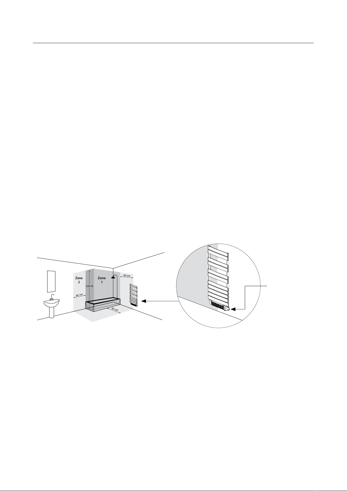
•In bathrooms (with bath or shower), install the appliance outside zone 1.
•The appliance must be installed in such a way that the electronic controls and other control devices
may not be touched by someone in the bath or shower. The towel warmer must not be connected
with a plug.
•This product comes with a 900mm colour coordinated cable (no plug), so it can be spur wired to the
heating circuit.
•To avoid all risks for young children, install the appliance with the lowest heating element at least
600 mm from the floor.
•No need to maintain or service this product once installed. However, should any technical problems
arise, contact a qualified professional or your local dealer. All operations on the appliance must be car-
ried out by a qualified professional who before performing maintenance must make sure the appliance
is turned off, cold and disconnected from the household mains.
150 mm MIN 150 mm MIN
110 mm MIN
150 mm MIN600 mm MIN
A
B645 mm
150 mm MIN 150 mm MIN
110 mm MIN
150 mm MIN600 mm MIN
Zone
2
Zone
1
Pavimento / Floor / Sol / Fußboden / Suelo
Pavimento / Vloer / Posadzka / Tlak
Dispositivo di comando
IT
Control device
GB
Dispositif de commande
FR
Bedienblende
DE
Dispositivo de mando
ES
Dispositivo de comando
PT
Bedieningsapparaat
NL
Urządzenia zabezpieczające
PL
Naprava za upravljanje
SI
* Zona / Zone / Bereich / Strefa / Področje
FIG. / ABB. / RYS. / SLIKA
1
FIG. / ABB. / RYS. / SLIKA
2
FIG. / ABB. / RYS. / SLIKA
3
FIG. / ABB. / RYS. / SLIKA
4
FIG. / ABB. / RYS. / SLIKA
7
FIG. / ABB. / RYS. / SLIKA
5
FIG. / ABB. / RYS. / SLIKA
8
FIG. / ABB. / RYS. / SLIKA
6
FIG. / ABB. / RYS. / SLIKA
9
A
B
N
D MC LI
E
G
F
H
Control device
EFLOW ELECTRIC TOWEL RADIATORS

AGATA EFLOW EFLOW ELECTRIC TOWEL RADIATORS
Electrical connection
•To be installed by a specialised engineer in accordance with the applicable standards in the
country concerned.
•When the appliance is installed, make sure the power is off and the mains switch is in the “O“ position.
•The appliance requires a 230 V ~ 50 Hz power supply. Make sure the power line is appropriate for the
data shown on the appliance’s rating plate.
•Make sure the fixed power line is fitted with a disconnecting switch allowing the appliance to
be disconnected completely from the household mains, included the Pilot Wire, when present,
in accordance with the wiring rules.
•If the appliance is installed in a bathroom, the power line must be fitted with a 30 mA RCD
(high sensitivity residual current protection device). The power supply line and Pilot Wire
control unit must be protected by the same RCD.
•Permanently connected appliances must be connected using a connector block placed within
a proper junction box.
•When installing the appliance in damp rooms (kitchen, bathroom), the point of connection
with the household mains must be at least 25 cm from the floor.
•If the Pilot Wire is not connected to the programming unit, it must be terminated and insulated.
Under no circumstances should the Pilot Wire be connected to the earth.
•Make sure the power cable cannot in any way come into contact with the surface of the appliance.
22
GB
23
Modifying the characteristics of the appliance and
removing any xed component including the caps
and/or removing or rotating the control device in any
3. POSITIONING AND INSTALLING
This appliance is designed to heat domestic rooms or similar
and to dry towels.
WARNING:
This appliance is designed to dry towels washed in water
only. It must not be used for other purposes. The appli-
ance must be used permanently mounted on a wall as
described in the instructions. Install the appliance with
the control device at the bottom right and the control
buttons towards the front as in Fig. 3.
Do not install the appliance with the fan facing up-
wards
In bathrooms (with bath or shower), install the ap-
pliance outside zone 1.
The appliance must be installed in such a way that
the electronic controls and other control devices
may not be touched by someone in the bath or
shower. The towel warmer must not be connected
with a plug.
2. GENERAL INFORMATION
Storage and maintenance:
Avoid storing the appliance in places at risk of
freezing.
Protect from frost.
Unpack the appliance carefully and rest it on the
polystyrene corner pieces or a soft support to avoid
damage.
The package contains:
– the appliance
–
remote control with two batteries and container for
wall mouting
– mounting kit
– instructions
Read all the instructions carefully before installation
and use. Keep for future consultation.
Install and use the appliance as described in these
instructions only.
These instructions do not cover all situations which
might arise. Caution and common sense should be
applied when installing, operating and servicing the
appliance.
A Brand/Manufacturer
B Model, type, category
C Voltage and Power
D Double isolation
E Country of origin
F EC marking
G Serial Number
H Product Code
The appliance’s technical specications are indicated on the rating plate on the bottom right of the towel warmer (Fig. 1).
1. SPECIFICATIONS OF THE APPLIANCE
Voltage: 230 V~ 50 Hz
Insulation class: II
Protection class IP24
way are expressly prohibited (Fig. 2).
Make sure the appliance is complete and undam-
aged. If damaged, do not use the appliance, but con-
tact your local dealer or a qualied professional.
The materials used for packaging can be recy-
cled. You are therefore recommended to dispose
of them in special differentiated waste collection
containers.
I Protection class
L Quality marks
M Disposal procedures
Table 1
Total
power
[W]
Towel warmer
+ fan power
[W]
Model with symmetrical
flat tube Model with tube
(Ø 25 mm) Model with
asymmetrical flat tube Model with symmetrical
flat tube (50x10 mm) Model with tube
(Ø 22 mm)
Size
[ l x h mm ]
A ( I )
mm B ( h )
mm
Size
[ l x h mm ]
A ( I )
mm B ( h )
mm
Size
[ l x h mm ]
A ( I )
mm B ( h )
mm
Size
[ l x h mm ]
A ( I )
mm B ( h )
mm
Size
[ l x h mm ]
A ( I )
mm B ( h )
mm
1500 500+1000 550x850 410 693
1500 500+1000 550x1090 410 881 550x890 410 608 600x1203 410 985 550x980 410 773 550x1056 410 798
1500 500+1000 550x1190 410 974
1700 700+1000 550x1322 410 1113 550x1220 410 974 600x1528 410 1310 550x1345 410 1098 550x1281 410 1023
1700 700+1000 550x1420 410 1205
2000 1000+1000 550x1730 410 1513 550x1710 410 1469 600x1852 410 1635 - - - 550x1220 410 983

AGATA EFLOW
Controls
Control Panel Control Panel LEDs
GB
26
27
USING THE APPLIANCE FROM THE CONTROL PANEL:
CYCLE
15 min
Infrared Receiver
Cycle Button
Fan Heater key
Main switch
MANUAL Button
LED “L5”
LED “L4”
LED “L3”
LED “L2”
LED “L1”
Clogged lter light
Never touch the appliance with wet or damp hands
or feet.
Do not wet the electronic control unit with water or
other uids. If this occurs, disconnect the appliance
from the mains power supply and allow to dry com-
pletely.
When the appliance is installed at high altitude, the air
will be hotter than the set temperature.
If you think room temperature could drop below freez-
ing point, activate the “Anti-freeze” mode.
To turn off the appliance completely, switch off
the main switch by moving it in the “O” position.
This is recommended whenever the appliance is
not used for long periods.
4. REGULATION AND OPERATION
This appliance is designed to heat
domestic rooms or similar and to
dry towels.
Some parts of this product can be-
come very hot and cause burns.
Particular attention has to be given
where children and vulnerable peo-
ple are present.
Keep combustible or ammable ma-
terials or pressure vessels (e.g. spray cans, re ex-
tinguishers) at least 50 cm from the appliance. Do
not vaporise any type of substance on the surface
of the appliance.
26
GB
27
4. 3.1 CyCLE
Use the “Cycle” function to heat the room or dry towels or
garments more quickly.
To activate “Cycle” mode, press the “Cycle” but-
ton until LED “L1” becomes green.
The appliance heats for 60 minutes at maximum power, ir-
respective of the set temperature.
4.2.3 ANTI-FREEZE
In “Anti-Freeze“ mode the temperature set point is xed at
7 °C. The appliance starts heating when room temperature
goes under 7 °C and with low energy consumption it pre-
vents the room temperature to reach the freezing point.
This operating mode is recommended when no people is in
the room for more than 1 day.
To activate “Anti-Freeze” mode, press the
“MANUAL” button until LED “L4” turns green.
4.3 FUNCTIONS
The appliance has a number of special functions to custom-
ise and optimise use.
4.2.2 PILOT WIRE
To activate “Pilot Wire” mode, press the “MANUAL” button until
LED “L3” turns green.
The house must be tted with a home
management system using this type of technology. To verify
correct transmission of the programming commands, follow
the scheme below according to the mode set.
If the Pilot Wire programmer is not connected, “Comfort”
operating mode is selected automatically.
Mode
Comfort
Night/Eco
(Comfort
-3.5 °C)
Anti-Freeze Standby Comfort
-1 °C
Comfort
-2 °C
Signal to be
transmitted
Voltage
between
Pilot Wire and
neutral wires
0 volt 230 volt 115 volt
Negative
115 volt
Positive
230 volt For
an interval
of 3 s
230 volt For
an interval
of 7 s
CYCLE
CONTROL PANEL LEDS
“L1” Cycle, Fan , Green
“L2” Comfort, Night/Eco, Chrono , Green
“L3” Pilot Wire Green
“L4” Anti-Freeze, Open Window Green
“L5” Standby Red
4.1 ON/STANDBy
To turn the appliance on, place the main
switch on the control panel in the “I” position.
The towel warmer turns on in the previously
selected operating mode and emits a beep.
To turn the appliance off completely, place the
switch in the “0” position.
To activate “Standby” mode, press the “MANUAL” button until
LED “L5” turns red.
The appliance can be controlled by the infrared remote con-
trol with LCD display or manually by the control panel.
4.2 OPERATING MODES (CONTROL PANEL)
The appliance provides 3 operating modes which allow the
user to heat the environment in the most suitable way with
respect to their needs.
MANUAL BUTTON
The MANUAL button can be used to select the appliance’s
principal operating modes without using the remote control
and to cancel the “Open Window“ action (see chap. 4.3.3).
Press the “MANUAL” button to select the following modes
in sequence: “Comfort“, “Pilot Wire“, “Anti-Freeze“,
“Standby“. The corresponding LED lights up.
4. 2.1 COMFORT
“Comfort” mode is designed for normal use of the appliance
to heat the room.
To activate “Comfort” mode, press the
“MANUAL” button until LED “L2” turns green.
Pilot Wire Comfort
Anti-Freeze
The factory set temperature is 19 °C. To modify this
temperature, use the “+” and “-” buttons on the remote
control.
28
GB
29
Never use at batteries and new batteries together,
always use batteries of the same type and brand.
Flat batteries must be removed from the appliance
immediately and disposed of appropriately. When
replacing the batteries or disposing of the remote
control, the batteries must be removed and dis-
posed of in compliance with current legislation as
they are harmful to the environment. Never throw
batteries into a re.
Keep batteries away from children.
Children may change batteries only if supervised
by an adult.
Remove the batteries if you will not be using the
appliance for a long period.
Take appropriate precautions when handling leak-
ing batteries!
Avoid contact with the skin, eyes and mucous
membranes.
If you come into contact with the battery liquid,
rinse the parts affected immediately with plenty of
water and seek medical advice immediately.
Characteristics:
5 m MAX
Fig. 12
The remote control can be placed in the wall mount in-
cluded in the packaging.
Do not drop the remote control nor leave it exposed to direct
sunlight. Do not spray water or other liquids onto the remote
control.
Do not place the remote control on top of the appliance or
close to intense heat sources.
Inserting or replacing the batteries:
• Remove the cover on the back of the remote control.
• Insert two “AAA” LR03 1.5 V alkaline batteries. When in-
serting the batteries, always respect the polarity (+ and
-) indicated on the battery and the appliance.
• Put the cover back.
REMOTE
CONTROL
Display LCD
“Mode“ selection key
Size 100 x 42 x 20.5 mm
Power supply “AAA” LR03 1.5 V alkaline
batteries
“+“ key
“-“ key
Fan Heater key
ON/Standby keyOverdrive (2h) key
GB
30
31
TURNING ON FOR THE FIRST TIME
After inserting the batteries, set the day of the week and
time.
Adjust the day of the week by using the “+“ or “-“
keys (1=MON, 2=TUE,…7=SUN), then conrm by
pressing the “Mode“ selection key.
The hour starts ashing. In the same way, ad-
just the hour by using the “+“ or “-“ keys and
conrm with “Mode“ selection key.
Minutes are now ashing: repeat the same pro-
cedure.
ON/STANDByMODE
In “Standby” mode the current time and the day of the week
appear on the display.
NOTE:
If the appliance is turned on using the remote control after it
has been without power, the date, time and program set on
the remote control will be restored.
The appliance responds to the commands received from the
remote control with the ashing of LED “L5”.
Signal transmission from the remote control to the appliance.
DISPLAy
Fan Heater
Clock
Chrono temperature Set
Chrono program time bar
Days of the Week
Keypad Lock
Chrono presets
Overdrive (2h)
Children Safety
Signal broadcast
Temperature set point/Fan heater timer
Operating modes
Press the “ON/Standby” key by aiming the re-
mote control at the control panel to turn the
appliance and the remote control on in the op-
erating mode active before the appliance was
turned off.
If the batteries in the remote control have been replaced, the
appliance resumes operation in “Comfort” mode.
The appliance emits a double beep when it enters the ”Stand-
by” mode and a single long beep when it exits the ”Standby”
mode.
IMPORTANT: After having pressed the ”Standby” but-
ton on the control panel, the appliance ignores all orders
transmitted by the remote control other than ”Standby” and
emits a beep to indicate the error.
Compared to the control panel, the remote control offers
the possibility to only activate certain operating modes and
functions.
OPER ATING MODES (REMOTE CONTROL)
The appliance provides 5 operating modes which allow the
user to heat the environment in the most suitable way with
respect to his needs.
All the operating modes are suspended (“Pilot Wire“ includ-
ed), but the appliance is powered and waiting for command
reception.
Press the “Mode“ selection key to select the
desired operating mode. An icon on the LCD
will show the selected operating mode.
27
MAX: 2 m
FIG. 10
Always handle the remote control with great care and place it within the
special plastic container for wall mounting, included in the packaging.
Do not drop the remote control nor leave it exposed to direct sunlight. Do
not spray water or other liquids onto the remote control. Do not place the
remote control on top of the appliance or close to intense sources of heat.
INSERTING OR REPLACING THE BATTERIES
1) Remove the cover on the back of the remote control.
2)Insert two “AAA” LR03 1.5 V alkaline baeries. When inserting the
baeries, always respect the polarity (+ and -) indicated on the baery
and the appliance. Baeries not included.
3) Put the cover back.
Never use flat baeries and new baeries together, always use baeries
of the same type and brand.
Flat baeries must be removed from the appliance immediately and
disposed of appropriately. When replacing the baeries or disposing
of the remote control, the baeries must be removed and disposed
of in compliance with current legislation as they are harmful to the
environment. Never throw baeries into a fire.
Keep baeries away from children. Children may change baeries only if
supervised by an adult. Remove the baeries if you will not be using the
appliance for a long period. Take appropriate precautions when handling
leaking baeries!
Avoid contact with the skin, eyes and mucous membranes.
If you come into contact with the baery liquid, rinse the parts aected
immediately with plenty of water and seek medical advice immediately.
OPERATION
STAND-BY STATE BY RC
In “Standby” mode the LCD displays the Standby icon, the hour and day of
the week.
All the operating modes are suspended (“Pilot Wire” included), but the
appliance is powered and waiting for command reception. To turn on or
o the appliance, press the “Standby” key. The radiators turns on in the
previously selected operating mode and emits a beep.
In “Chrono” mode the display shows the time, in the other modes the
temperature seing is displayed.
The entry into “Standby” mode is signalled by means of a double beep, the
exit from “Standby” mode by means of a long beep.
TURNING ON FOR THE FIRST TIME
After inserting the baeries, set the year, month, day of the week and time.
Adjust the day of the week by using the “+” and “-” keys (1=MON, 2=TUE,…
7=SUN), then confirm by pressing the “Mode” selection key. The hour starts
flashing. In the same way, adjust the hour by using the “+” and “-” keys and
confirm with “Mode” selection key. Repeat the same procedure for the
minutes. The year of start is 2019.
PILOT WIRE
TO ACTIVATE THE “PILOT WIRE” MODE
Press the “Mode” selection key until the
icon appears on the LCD .
Users can only set the “Comfort” temperature on the appliance. Select the
desired temperature set point by using the “+” or “-” keys.
The home must be fied with an automation system supporting this type
of technology. In this case, correct transmission of the programming
commands can be verified using the following diagram according to the
mode set: (see table 1).
The icon showing the mode selected on the control unit (Standby,
Comfort, Night/Eco, Anti-Freeze) is displayed together with the icon.
If the Pilot Wire programmer is not connected, “Comfort” operating mode
is selected automatically.
Mode Comfort Night/
Eco
(Comfort
-3,5 °C)
Anti-
Freeze
Standby Comfort
-1°C
Comfort
-2°C
Signal to be
transmied
Voltage
between
Pilot Wire
and neutral
wires
XXX volt 230 volt 115 volt
Negative
115 volt
Positive
230 volt
For an
interval
of 3 s
230 volt For
an interval
of 7 s
COMFORT
The “Comfort” temperature corresponds to the temperature desired by
the user. All “Pilot Wire” commands are disabled.
Press the “Mode” selection key until the icon appears on the LCD.
Select the desired temperature set point by using the “+” or “-” keys.
The temperature can be choosen in the interval between 13 °C and 30 °C.
The behavioural indicator allows you to check if the chosen temperature
set point is aligned with the recommended guidelines, in order to avoid the
waste of energy and reduce the energy consumption.
An arrow will appear by one of the three colored bars that represent
the energy consumption in a qualitative way, according to the
following scheme:
(a)Green Dark:The chosen temperature set point is already lower than
the recommended. Heating on.
(b)Green Light:The chosen temperature set point is adequate, but it would
be beer to further decrease it. Heating on.
Red:The chosen temperature set point is high, it would be beer to
decrease it. Heating on.
(d)Green Dark Flashing:The chosen temperature set point is already
lower than the recommended. Heating o.
(e)Green Light Flashing:The chosen temperature set point is adequate,
but it would be beer to further decrease it. Heating o.
(f)Red Flashing :The chosen temperature set point is high, it would be
beer to decrease it. Heating o.
NIGHT/ECO
In “Night/Eco” mode the temperature set point must not be higher than
“Comfort” temperature set point.
If the “Comfort” temperature is set below the “Night/Eco” temperature,
the laer will be automatically adjusted accordingly.
Press the “Mode” selection key until the icon appears on the LCD.
Select the desired temperature set point by using the “+” or “-” keys.
The use of this operating mode is recommended in nighime hours and
in case no people are in the room for more than 2 hours. Default night is T
comfort -3°C.
ANTI-FREEZE
In “Anti-Freeze” mode the temperature set point is fixed at 7 °C. The appliance
starts heating when room temperature goes under 7 °C and with low energy
consumption it prevents the room temperature from reaching freezing point.
Use
Remote control
The remote control communicates with the appliance by
infrared rays. For efficient communication, point the remote
control at the receiver on the appliance). The distance
between the remote control and the receiver must not be
more than 5m.
The appliance responds to the commands received from the
remote control with a beep lasting about 2 seconds.
Display
EFLOW ELECTRIC TOWEL RADIATORS
Operating modes (for the Control Panel and Remote Control)
Pilot Wire (n/a in the UK) Comfort Night / Eco Chrono Anti-freeze Standby
Functions (for the Control Panel and Remote Control)
Cycle Fan heater Open window Child safety Override Keypad lock
MAX: 5m
This manual suits for next models
7
Table of contents
Other Stelrad Heater manuals

Stelrad
Stelrad ELECTRIC Series User manual

Stelrad
Stelrad ELECTRIC Series User manual

Stelrad
Stelrad Regal User manual

Stelrad
Stelrad ELECTRIC Series User manual

Stelrad
Stelrad LECCO User manual

Stelrad
Stelrad ELECTRIC Series User manual

Stelrad
Stelrad Alyne GYA0610F User manual

Stelrad
Stelrad ELECTRIC Series User manual

Stelrad
Stelrad E-VENTO 0184B0002 Guide

Stelrad
Stelrad ELECTRIC Series User manual


