Stepp SMT series User manual

OPERATIONS/MAINTENANCE/PARTS
MANUAL
LP or Diesel Burner Systems
12325 River Road North Branch MN 55056 ~ Phone: 651-674-4491 ~ Fax: 651-674-4221
www.steppmfg.com
Rev. 12/2014

2
Warranty
Stepp Manufacturing Company Inc. hereby warrants to the original purchaser that products
manufactured by Stepp Mfg. will be free from defects in material and workmanship for a
period of one (1) year from the date of purchase.
Stepp Mfg., at its discretion, will provide for the repair or replacement of any part found
upon examination by Stepp Mfg. to be defective, except as noted below. Such repair or re-
placement will be free of charge to the original purchaser for a period of one (1) year from
the date of purchase, except as noted below.
No warranty is extended to cover:
•Product pump wear or damage caused by foreign objects.
•Routine maintenance, cleaning, and adjustments.
•Parts/components that have been altered, misused, or improperly adjusted or maintained.
•Transportation to and from the place of warranty repair.
•Removal of material from equipment.
The following items are covered solely by their manufactures warranty:
•Engines
•Hydraulic components
•Burners
•Pumps
•Tires
•Other component parts
The following items are covered by a pro-rata warranty:
•Hoses that carry heated materials.
•Heating elements for hoses and wands.
Disclaimer of further warranty:
Stepp Mfg. makes no warranty, expressed or implied, other than this warranty. The implied
warranties of merchantability and fitness for particular purpose are hereby disclaimed. Re-
pair or replacement of products or parts proving to be defective in material or workmanship
shall be the exclusive remedy for breach of this warranty.
Stepp Mfg shall not be liable for incidental or consequential damages including but not
limited to: damages for inconvenience, rental or purchase of replacement equipment, for
loss of profits, loss of material, or other loss resulting from breach of this warranty.
Stepp Mfg reserves the right to incorporate any changes in design into its products without
obligation to make such changes on products previously manufactured.
Please see Warranty section for more details.
Stepp Manufacturing Co., Inc.
12325 River Road
North Branch, MN 55056
P: 651-674-4491 F: 651-674-4221
www.steppmfg.com

3
INTRODUCTION
SMT Mini Tanker
Thank you for selecting Stepp highway maintenance equipment. We are confi-
dent you will be satisfied with the Stepp SMT Mini Tanker. Stepp Manufacturing
is backed by over 70 years of experience in the design and manufacture of high-
way maintenance equipment. This experience along with our innovative design
and unique features make the Stepp SMT the most efficient Mini Tanker availa-
ble. Continued research and development, along with input from you, the user,
help make this possible.
To assure safe operation of this equipment, the operator must read and under-
stand all operating procedures and safety notices contained in this manual. In
addition, the operator must receive proper instruction on how to safely operate
the Stepp SMT. Contact the manufacture if any questions arise or if you desire
training for additional staff members.
Operating instructions, adjustments and periodic maintenance procedures are
given so you, the operator, can keep your unit working like new and expect
many years of dependable service from it. Remember, any machine, regardless
of design or type, will perform only in relation to the way it is operated and the
maintenance it receives.
Read this manual carefully and observe all Warnings and Cautions. If you have
any recommendations or comments regarding this manual, please send them
attention to: Engineering Dept., Stepp Manufacturing Co. Inc., 12325 River
Road, North Branch MN. 55056-6225 or call 651-674-4491.
When ordering parts or making any inquiry about the Stepp SMT be sure to in-
clude the model number and serial number found on the data plate attached to
the frame.

4
TABLE OF CONTENTS
Introduction 3
Contents 5
Operations 7
Maintenance 17
Troubleshooting 21
Parts 27
NHTSA Reporting Safety Defects 38
Warranty Guide 39
Watlow Programming 45
Schematics 55
Hydraulic Oil MSDS 57
Engine Inserts 69
IMPORTANT NOTICE!
This manual contains cautions and warnings that alert you to potential safety issues.
WARNING is used to inform you of conditions or operations that could cause serious injury or death.
CAUTION is used to inform you of conditions or operations that could cause damage to the equipment
NOTE is used to provide you with additional information that may be helpful or useful for a particular situation.
This manual explains the basic operations, maintenance and use of the Stepp SMT Mini Tanker. The main ob-
jective of this equipment is to heat, transport, store, and apply various asphalts and emulsions for crack filling,
seal coating, and priming of road surfaces. An optional engine driven pump may be installed to deliver heated
product to the road surface through a wand or spray bar.

5
Before Starting or Operating this Machine
Understand and observe all the following Warnings, Cautions, and Notes.
WARNINGS
This equipment contains mechanical and heating components that may cause serious injury or death if not
handled or maintained properly. All personnel must be properly trained in the operation and maintenance of
this equipment.
Before refueling, shut off the burners and allow all flames in the burner and pilot light to extinguish. Shut off
the engine.
Check fuel lines, fuel line connections, and all other components for leaks. If any leaks are found, they must
be repaired before using the unit.
Know the temperature required for the material being used, and do not exceed this temperature. Avoid over
heating, as this may cause equipment damage, personal injury, and/or death.
Never load a tank with heated oil when moisture is present in the tank. Depending on the temperature of the
hot oil, the moisture may instantly boil causing hot oil to foam up and out of the tank causing severe burns.
Do not operate the tack tank burner when the amount of material in the tank is less than 4" above the flues.
Allow 10 minutes cool-down time after the burner has been shut off before exposing the flues. Exposed flues
will over-heat and cause an explosion and/or fire.
The tack tank cover must be unlatched when operating the tack tank burner. This is to provide for emergen-
cy venting, in the event of a flash, to prevent the tank from exploding.
CAUTIONS
Know the materials being used and know the proper handling, heating, application, clean-up, and storage
procedures. Not all materials are compatible with each other. Many materials have a very limited shelf life.
Most materials require special handling procedures to prevent personal injury and/or equipment damage.
Contact your material supplier and/or manufacturer for proper handling instructions. Equipment malfunction
or damage due to improper handling or use of the materials is not covered by warranty.
Do not exceed the maximum heating temperature or storage time as recommended by the material manu-
facturer. This may cause emulsion type materials to separate and become difficult or impossible to remove
from the machine. Consult with the material manufacturer for recommendations.
Over-agitation or circulation may cause emulsion type materials to separate and become difficult or impossi-
ble to remove from the machine. Consult with the material manufacturer for recommendations.
Do not mix Anionic and Cationic materials together, as the materials attach to each other and will become
difficult or impossible to remove from the machine. If you are not sure consult your material supplier.
NOTES
Become familiar with the Material Safety Data Sheet (MSDS) for the material being used in the machine and
take appropriate safety precautions. Wear the proper clothing and protective gear as recommended by the
MSDS and your safety director.
DO NOT use the equipment unless it is in good condition.
In case of skin contact with hot materials, dip into cool, clean water immediately. Do not wipe the product,
as this will spread the burn.
Consult the MSDS and contact your safety director for proper extinguishing of petroleum based fires.
Carry a fire extinguisher(s) as recommended by your safety director.
Notify your supervisor or the manufacturer if any questions arise concerning the operation of this equipment.

6

7
OPERATIONS
8
OPERATIONS Transporting
WARNING: Prior to transporting, the driver of the tow vehicle must assure the safety of the
operation. The driver must also know, and assure, the product temperature is within limits.
Trailer Hook-up
1. Connect trailer to towing vehicle.
a. Check that hitch is engaged properly.
b. Attach safety chains to towing vehicle.
c. Connect battery charging circuit to tow vehicle if required.
d. Connect electrical plug to towing vehicle.
e. Connect breakaway cable to towing vehicle.
f. Check operation of lights and brakes.
2. Secure trailer for transport.
a. Shut OFF the engine and burners.
b. Shut OFF all fuel valves.
c. Be sure the product temperature is not above the recommended operating tempera-
ture.
d. Securely latch the tank cover.
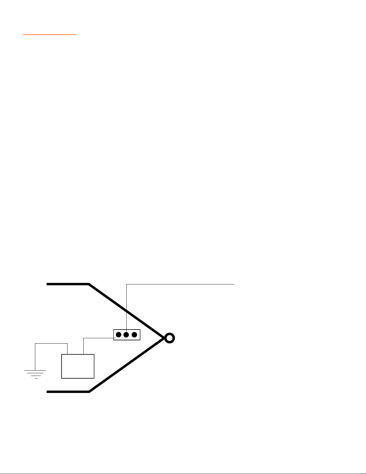
12 volt
battery
Connection to the tow vehicles battery is required
when the Stepp SMT is equipped with spark ignition or
electronic thermostats and does not have its own
charging system. (ie: onboard engine or generator)
The isolator will protect the battery on the trailer from
discharging through the tow vehicles electrical system.
+
-
Connect to 12 volt power on tow vehicle
14 GAUGE RED
ISOLATOR
TRAILER

9
1. Loading Procedures:
a. Check that the proper material is being used.
b. The tank must be thoroughly cleaned if the material being loaded is not compatible
with that already in the tank. Check with your material supplier for compatibility.
c. Tank is loaded through top manhole cover.
WARNING: Never load a tank with heated oil when moisture is present in the tank. Use cau-
tion when loading to avoid splashing hot material on yourself or others.
OPERATIONS Loading

10
OPERATIONS LP Burner w/ Thermostat
This system uses electrical sparks to ignite the pilot lights that, in turn, ignite the burners. If
the pilot light goes out, the system will attempt a re-ignition. If the re-ignition is not successful,
the gas supply will automatically be shut off and the system must be vented before resetting
the system. The system is reset by switching the 12 volt power supply OFF then ON again.
By use of a thermostat, the system automatically controls the burners to maintain the desired
product temperature.
WARNING: BEFORE IGINITING BURNER: Know the materials being used. DO NOT exceed
flash point or operating range temperatures.
Igniting Burner
1. Turn OFF burner and pilot valves.
2. Attach liquid LP bottle to system and set regulator between 10 and 20 PSI, depending
on intensity of flame desired.
3. Open pilot light valve.
4. Turn on main power switch and a clicking sound can be heard as the ignition system
starts to work.
5. When the pilot light ignites, proceed to next step. If ignition has failed, reset power
switch. NOTE: The ignition system is designed to sense flame at the pilot light to act as
flameout protection. If flame is not present within approximately six seconds, the igni-
tion igniter will drop out and require resetting with the power switch.
WARNING: The burner chamber will require venting to eliminate the possibility of gas build
up after each ignition reset.
6. Open burner valve then set thermostat to the desired temperature and the burner will
ignite.
7. Operate engine or other charging circuit as necessary to provide power to the thermo-
stat and spark ignition system.
To Shut Off Burners
1. Turn off power switch on the control box.
CAUTION: When storing the equipment, turn off fuel supply tank valve and allow the fuel sys-
tem to burn off. This will prevent temperature changes from building excess pressure in the
system and possibly damaging components. Then turn OFF the power switch.

11
When equipped with a Baso Safety Valve, this system will shut off the gas supply to the burn-
ers if the flame should go out for any reason. This system is not equipped with automatic tem-
perature controls. It is the operators responsibility to shut off the burners when the product
reaches the recommended temperature. Allow for temperature “creep” when the burners are
shut off.
Igniting Burner
1. Verify that the main burner valve and lighting wand valve are OFF.
2. Attach Liquid LP bottle to system and set regulator between 10 to 20 PSI, depending
on intensity of flame desired.
3. Open pilot light control valve between four to six turns.
4. Open lighting wand valve ¼ to ½ turn and light immediately to prevent gas build-up and
fire hazard.
5. Insert lighting wand near outlet of pilot light.
6. Push the button on the safety control valve (baso valve).
7. Once the pilot light has ignited, hold the button down 30-45 seconds, or until it stays
energized by itself.
8. Once the pilot light is lit and the Baso Valve is staying in the operating position, close
valve on lighting wand and store.
9. Open the main burner valve slowly until you acquire the desired flame.
To Shut Off Burners
1. Turn off the burner control valve and allow the burner to self-extinguish.
2. Close pilot light valve.
CAUTION: When storing the equipment, turn off fuel supply tank valve and allow the fuel sys-
tem to burn off through the lighting wand. This will prevent temperature changes from building
up excess pressure in the system and possibly causing damage to the equipment, or perso-
nell injury and/or death.
OPERATIONS LP Burner w/ Baso Valve
12
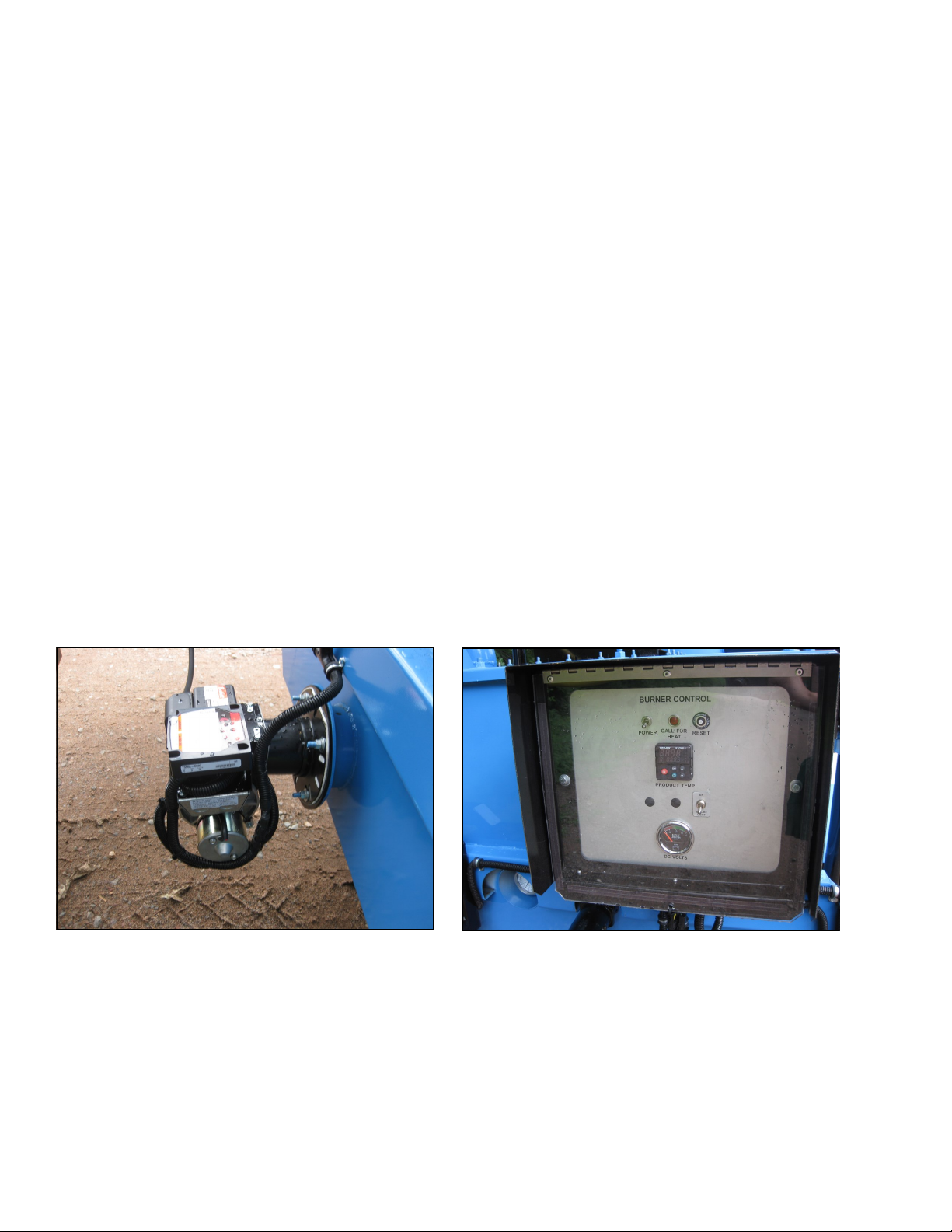
This system incorporates a 12 volt burner and blower assembly and burns #2 diesel fuel. A
12 volt battery and charging circuit supplies power to the burner, blower motor, and thermo-
stat. The charging circuit may consist of an engine driven alternator mounted on the unit, or a
hook-up to the tow vehicle’s charging system. The thermostat will automatically control the
burners to maintain the desired temperature. The temperature of the material is shown on
LCD digital displays.
Igniting Burner
1. Check fuel tank for proper fuel type and quantity.
2. Set thermostat to the product manufacturers recommended level.
3. Turn ON burner power switch and the burner will ignite.
4. Operate battery charging device.
To Shut Off Burner
1. Set thermostat to the lowest setting.
2. Turn OFF burner power switch.
CAUTION: The burner requires a minimum of 12 volts for proper operation. Poor combustion
with excessive smoke and lack of heat or burner malfunction will result with lower voltage. As-
sure the battery is fully charged and the charging circuit is operating properly for maximum
performance.
OPERATIONS Diesel Burner

13
OPERATIONS Pumping System w/ Spray Wand
An optional pump may be installed to pump material through a spray wand. The pump may
be driven by a gas or diesel engine or by an electrical or hydraulic system. The plumbing
must be purged of material when finished to prevent plumbing freeze-up. This is done by re-
versing the pump to suck the material out of the wand. An optional flush tank may also be in-
stalled to further flush the system of any remaining material. NOTE: All valves should be OFF
unless directed to be open.
1. Circulate. In this operation, the contents of the tank are pumped through the recirculation
system and directed back to the tank to aid heating and mixing.
a. Set Recirculate/Spray valve (2) to "Recirculate" position.
b. Open tank valve (1).
c. Engage pump in “Forward” direction.
2. Spray. In this operation, the contents of the tank are pumped to the wand for application
to the road surface.
a. Set Recirculate/Spray valve (2) to "Spray" position.
b. Open tank valve (1).
b. Engage pump in “Forward” direction.
c. Open valve on spray wand.
3. System Purge. (suck back) In this operation, the pump is “Reversed” to purge the product
from the system.
a. Disengage pump.
b. Set Recirculate/Spray valve (2) to "Spray" position.
c. Open tank valve (1).
d. Open valve on wand, then engage pump in “Reverse” for two minutes.
e. Close tank valve (1) and disengage pump.
14
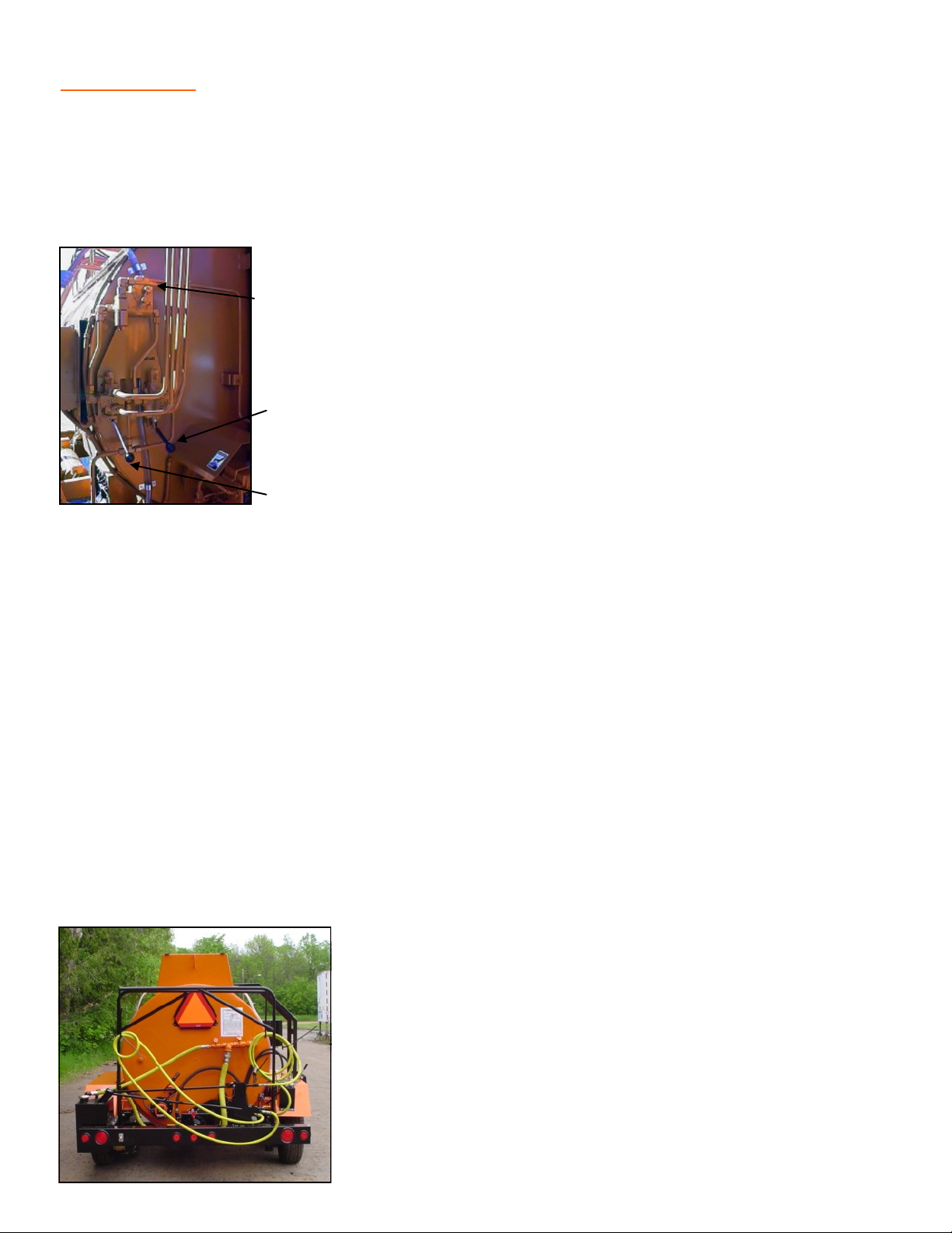
Product Pump Hydraulic Control Valve
Agitator Hydraulic Control Valve
Variable Flow Divider (Agitator RPM Control)
Agitator operation is control by a hydraulic control valve. Move the lever from the center posi-
tion to engage the agitator. The agitator may be operated in either forward or reverse direc-
tion. Adjust the variable flow divider to obtain the desired agitator RPM. (20 RPM recommend-
ed) Depending on the type of product used, the contents of the tank may need to be heated
before agitator operation.
Electric Heated Hose & Wand
This system incorporates heating elements located inside the hose and wand to heat the ma-
terial and prevent a plugged system. Power for the heating elements is supplied by a 24 volt
alternator mounted on the engine.
With this system, no suck-back or flushing of the hose & wand is needed. Activate the electric
wand heat control switch to melt the material in the hose & wand.
The Electric Wand heat control should be turned on 30 to 40 minutes before trying to pump
material through the hose and wand. This will allow time for the material to re-liquefy in the
hose.
CAUTION: DO NOT activate the electric wand heat unless the hose and wand have product
in them. Absence of product will cause the element to overheat and destroy the hose possi-
bly causing serious injury. Do not allow flushing solvent in the hose. The presence of flush
solvent in a heated hose will create a fire hazard. DO NOT activate electric heating elements
in an empty hose. DO NOT suck-back the material out of the hose & wand. DO NOT flush the
hose & wand.
OPERATIONS Agitator
15
The plumbing system must be sucked-back and flushed of material when operations are com-
plete or the system will plug and cause difficulty the next time the equipment is used. See
previous pages for material suck-back instructions and operational charts to assist in valve
operational placement. Be sure to select the appropriate chart to fit your equipment.
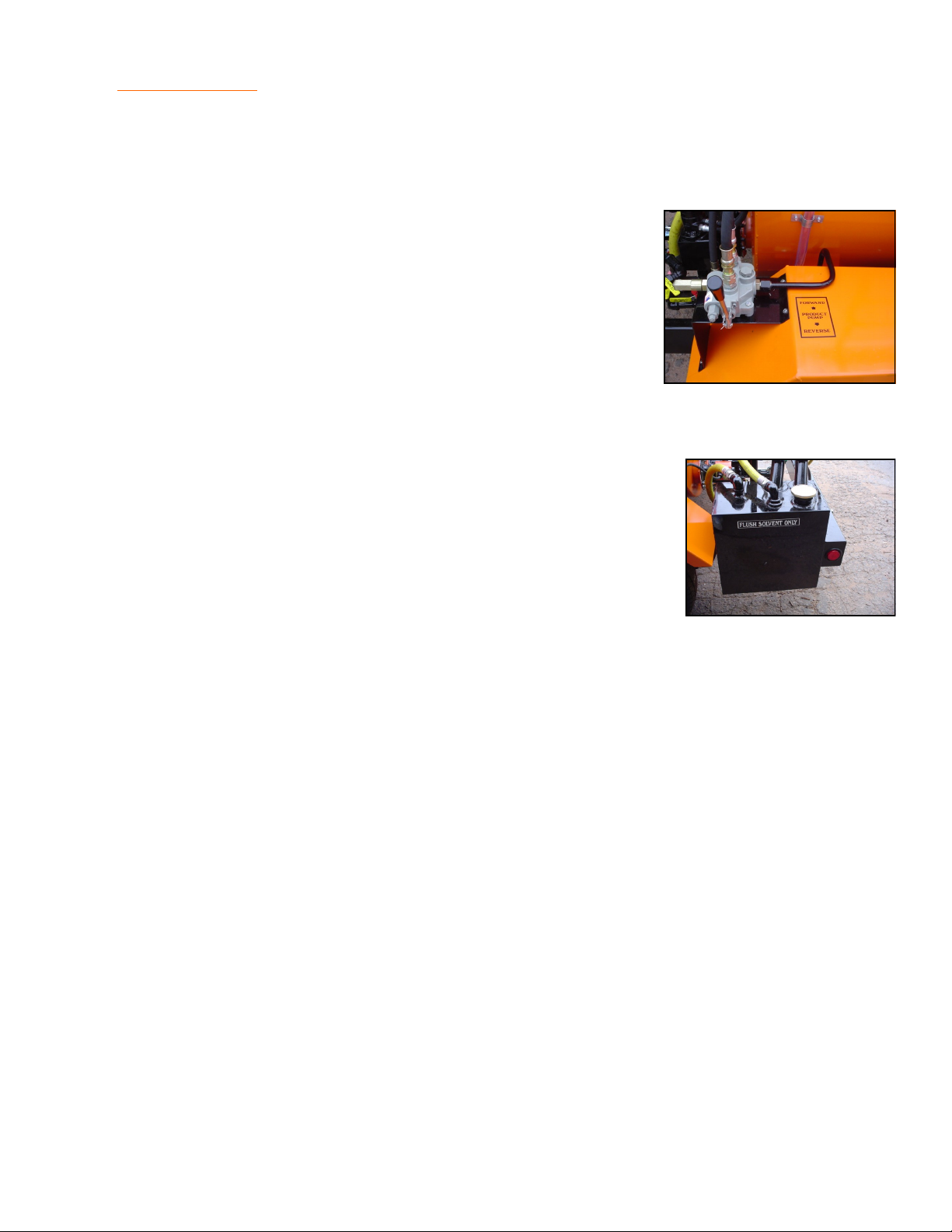
To "Flush" the System:
1. Tank valve must be closed for flushing and suck-back opera-
tions.
2. Set flush/product valve to "Flush" position.
3. Move the product pump hydraulic control to the "Pump" posi-
tion.
4. Hold flush switch in the "up" position to flush the system.
5. After 1 minute (minimum) release the flush switch then stop the product pump.
Suck-Back of Flush Solvent:
1. Close the tank valve and set flush/product valve to "Flush" posi-
tion.
2. Move the product pump hydraulic control to the "reverse" posi-
tion.
3. Open manual air valve located near manifold valve.
4. After 1 minute return the product pump hydraulic control the center (neutral) position.
5. Close manual air valve.
NOTE: The flush solvent circulates through the system back to the flush tank for reuse. After
a period of time the solvent in the flush tank will accumulate excessive sludge and become
ineffective. The flush tank will then need to be cleaned and replenished with fresh solvent. A
removable cover is located on the rear of the flush tank to allow access for cleaning the
sludge from the tank.
Freezing Weather Operations & Storage:
Emulsion materials must not be allowed to freeze. When operating in cold weather keep the
material heated and circulating to prevent freezing. A non-freezing flush solvent should be
used.
NOTE: When storing the equipment be certain:
All material has been drained from the tank, plumbing, and spray bar.
All the plumbing components have been thoroughly flushed with a non-freezing
flush solvent.
OPERATIONS Shutdown Procedures
16
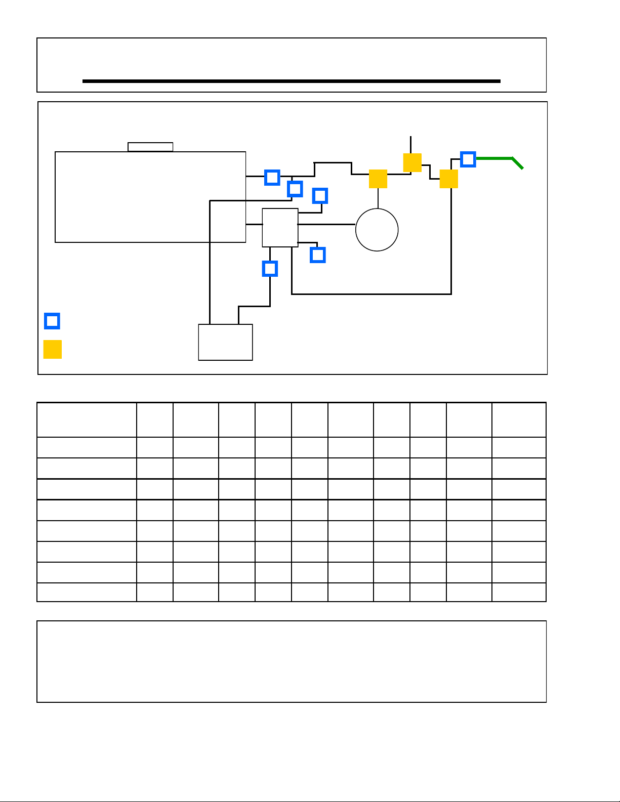
CAUTION: Do not allow flushing solvent to enter product tank. Do not operate heaters unless
heating elements are completely covered with a minimum of 6 inches of product. Note:
WPC=Wand pressure control valve. Position WPC valve handle between circulation and
spray to control wand pressure.
OPERATION V-1V-2V-3V-4V-5V-6
WPC
V-7V-9V-10 PUMP
Circulate ON Recirc Off Off Off Wand On Off N/A Forward
Wand On Wand Off Off Off WPC Off Off Wand Forward
Air Purge Wand Off Wand Off On Off Wand Off Off Wand Forward
Flush Wand* Off Wand On Off Off Wand Off Off Wand Forward
Pump Unload On Wand Off Off Off Recirc Off Off Unload Forward
Air Purge Plmb Off Recirc Off On Off Recirc On Off Wand Forward
Flush Plumbing Off Recirc On Off Off Recirc Off On Wand Forward
PRODUCT
TANK
Tank Valve
(7)
Flush Valve
(9)
Unload/Wand
Valve (10)
Air In
Valve (4)
Wand/Recirc
Valve (2) Wand/Recirc
Valve WPC (6)
WAND
UNLOAD
PUMP
FLUSH
TANK
Drain (5)
Flush
Valve (3)
Tank
Valve
(1)
7
94
2
1
6
5
3
* Wand position to
flush wand——
Re-circulate position to
flush re-circulating
plumbing.
= 2 Port Valve
= 3 Port Valve
PUMPING OPERATIONS
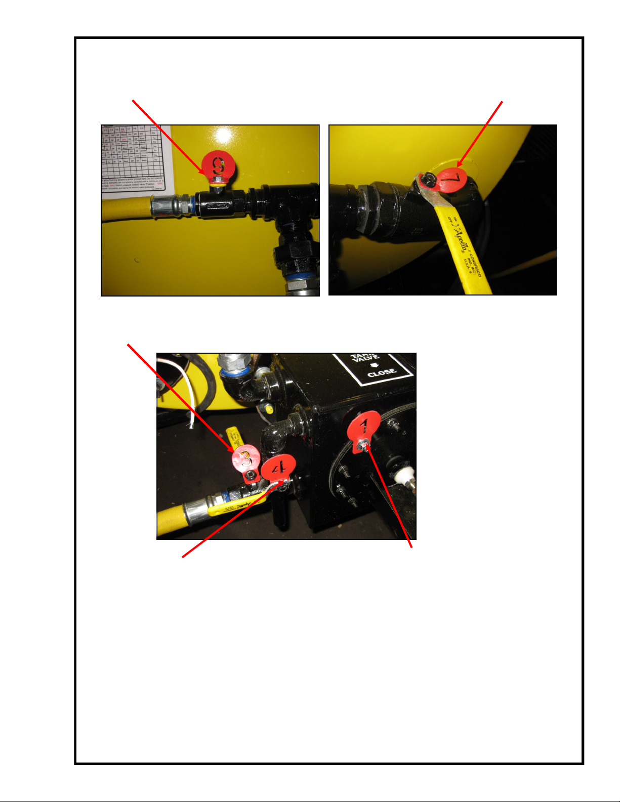
17
UPPER TANK VALVE (7)
FLUSH VALVE (3)
TANK VALVE (1)
PUMPING SYSTEM
FLUSH VALVE (9)
AIR IN VALVE (4)

18
WAND/RECIRC VALVE (2)
WAND/RECIRC
WPC
VALVE (6)
DRAIN (5)
UNLOAD (10)

19
MAINTENANCE

20
ITEM OPERATION TO PERFORM DAILY EVERY
WEEK
EVERY
MONTH
EVERY
3MO
EVERY
6MO
EVERY
YEAR
SMT MINI TANKER MAINTENANCE SCHEDULE
Table of contents
Other Stepp Industrial Equipment manuals


