Stepp OJK-H series User manual

OPERATIONS/MAINTENANCE/PARTS
MANUAL
Diesel Burner Systems
12325 River Road North Branch MN 55056 ~ Phone: 651-674-4491 ~ Fax: 651-674-4221
www.steppmfg.com
Rev. 12/2014

2
Warranty
Stepp Manufacturing Company Inc. hereby warrants to the original purchaser that products
manufactured by Stepp Mfg. will be free from defects in material and workmanship for a
period of one (1) year from the date of purchase.
Stepp Mfg., at its discretion, will provide for the repair or replacement of any part found
upon examination by Stepp Mfg. to be defective, except as noted below. Such repair or re-
placement will be free of charge to the original purchaser for a period of one (1) year from
the date of purchase, except as noted below.
No warranty is extended to cover:
•Product pump wear or damage caused by foreign objects.
•Routine maintenance, cleaning, and adjustments.
•Parts/components that have been altered, misused, or improperly adjusted or maintained.
•Transportation to and from the place of warranty repair.
•Removal of material from equipment.
The following items are covered solely by their manufactures warranty:
•Engines
•Hydraulic components
•Burners
•Pumps
•Tires
•Other component parts
The following items are covered by a pro-rata warranty:
•Hoses that carry heated materials.
•Heating elements for hoses and wands.
Disclaimer of further warranty:
Stepp Mfg. makes no warranty, expressed or implied, other than this warranty. The implied
warranties of merchantability and fitness for particular purpose are hereby disclaimed. Re-
pair or replacement of products or parts proving to be defective in material or workmanship
shall be the exclusive remedy for breach of this warranty.
Stepp Mfg. shall not be liable for incidental or consequential damages including but not
limited to: damages for inconvenience, rental or purchase of replacement equipment, for
loss of profits, loss of material, or other loss resulting from breach of this warranty.
Stepp Mfg. reserves the right to incorporate any changes in design into its products without
obligation to make such changes on products previously manufactured.
Please see Warranty section for more details.
Stepp Manufacturing Co., Inc.
12325 River Road
North Branch, MN 55056
P: 651-674-4491 F: 651-674-4221
www.steppmfg.com

3
INTRODUCTION
OJK Stepp Oil Jacketed Kettle
Thank you for selecting Stepp highway maintenance equipment. We are confi-
dent you will be satisfied with the Stepp Oil Jacketed Kettle. Stepp Manufactur-
ing is backed by over 70 years of experience in the design and manufacture of
highway maintenance equipment. This experience along with our innovative de-
sign and unique features make the Stepp Oil Jacketed Kettle the fastest and
most efficient kettle available.
In order to assure safe operation of this equipment, the operator must read and
understand all operating procedures and safety notices contained in this manu-
al. In addition, the operator must receive instruction on how to safely operate the
Stepp Oil Jacketed Kettle. Contact the manufacturer if any questions arise or if
you desire training for additional staff members.
Operating instructions, adjustments and periodic maintenance procedures are
given so you, the operator, can keep your unit working like new and expect
many years of dependable service from it. Remember, any machine, regardless
of design or type, will perform only in relation to the way it is operated and the
maintenance it receives.
Read this manual carefully and observe all warnings and cautions. If you have
any recommendations or comments regarding this manual, please send them
attention to: Stepp Manufacturing Co. Inc., 12325 River Road, North Branch
MN. 55056-6225 or call 651-674-4491. All comments we receive are reviewed
and may be incorporated into future manuals.
When ordering parts or making any inquiry about the Stepp Oil Jacketed Kettle,
be sure to include the model number and serial number found on the data plate
attached to the frame.

4
TABLE OF CONTENTS
Introduction 3
Contents 5
Warnings, Cautions, Notes 5
Quick Specs 6
Description 7
Operations 15
Maintenance 23
Troubleshooting 43
Replacement Parts 51
NHTSA Reporting Safety Defects 68
Warranty Guide 69
Watlow Programming 75
Schematics 85
Heat Transfer Oil MSDS 89
Hydraulic Oil MSDS 99
Engine Manual/Burner Manual Inserts
Air Compressor Manual/Tire Information Inserts
IMPORTANT NOTICE!
This manual contains cautions and warnings that alert you to potential safety issues.
WARNING is used to inform you of conditions or operations that could cause serious injury or death.
CAUTION is used to inform you of conditions or operations that could cause damage to the equipment
NOTE is used to provide you with additional information that may be helpful or useful for a particular situation.
This manual explains the basic operations, maintenance and use of the Stepp OJK Oil
Jacketed Kettle. The main objective of this equipment is to melt rubberized crack seal-
ing and water proofing compound and apply them to road surfaces.

5
Before Starting or Operating this Machine
Understand and observe all the following Warnings, Cautions, and Notes.
WARNINGS
This equipment contains mechanical and heating components that may cause serious injury or death if not
handled or maintained properly. All personnel must be properly trained in the operation and maintenance of
this equipment.
Before refueling, shut off the burners and allow all flames in the burner and pilot light to extinguish. Shut off
the engine.
Check fuel lines, fuel line connections, and all other components for leaks. If any leaks are found, they must
be repaired before using the unit.
Know the temperature required for the material being used, and do not exceed this temperature. Avoid over
heating, as this may cause equipment damage, personal injury, and/or death.
Never load a tank with heated oil when moisture is present in the tank. Depending on the temperature of the
hot oil, the moisture may instantly boil causing hot oil to foam up and out of the tank causing severe burns.
Do not operate the tack tank burner when the amount of material in the tank is less than 4" above the flues.
Allow 10 minutes cool-down time after the burner has been shut off before exposing the flues. Exposed flues
will over-heat and cause an explosion and/or fire.
The tack tank cover must be unlatched when operating the tack tank burner. This is to provide for emergen-
cy venting, in the event of a flash, to prevent the tank from exploding.
CAUTIONS
Know the materials being used and know the proper handling, heating, application, clean-up, and storage
procedures. Not all materials are compatible with each other. Many materials have a very limited shelf life.
Most materials require special handling procedures to prevent personal injury and/or equipment damage.
Contact your material supplier and/or manufacturer for proper handling instructions. Equipment malfunction
or damage due to improper handling or use of the materials is not covered by warranty.
Do not exceed the maximum heating temperature or storage time as recommended by the material manu-
facturer. This may cause emulsion type materials to separate and become difficult or impossible to remove
from the machine. Consult with the material manufacturer for recommendations.
Over-agitation or circulation may cause emulsion type materials to separate and become difficult or impossi-
ble to remove from the machine. Consult with the material manufacturer for recommendations.
Do not mix Anionic and Cationic materials together, as the materials attach to each other and will become
difficult or impossible to remove from the machine. If you are not sure consult your material supplier.
NOTES
Become familiar with the Material Safety Data Sheet (MSDS) for the material being used in the machine and
take appropriate safety precautions. Wear the proper clothing and protective gear as recommended by the
MSDS and your safety director.
DO NOT use the equipment unless it is in good condition.
In case of skin contact with hot materials, dip into cool, clean water immediately. Do not wipe the product,
as this will spread the burn.
Consult the MSDS and contact your safety director for proper extinguishing of petroleum based fires.
Carry a fire extinguisher(s) as recommended by your safety director.
Notify your supervisor or the manufacturer if any questions arise concerning the operation of this equipment.

6
This Oil Jacketed Kettle (double boiler) will be used to melt rubberized crack sealing
and water proofing compounds and apply them to the road surface. The machine shall be
the manufacturer’s current production model, trailer mounted, and completely self con-
tained. It shall be capable of heating, melting, and applying all grades of rubberized asphalt
crack sealer, joint sealants, and waterproofing compounds without the need for additional
equipment. The machine shall be capable of heating sealing material from ambient to appli-
cation temperature in 60 minutes or less.
Quick Spec OJK 185 OJK 275 OJK 400
Capacity 190 Gallon 280 Gallon 440 Gallon
Heat Transfer
Oil Capacity 110 Gallon 118 Gallon 130 Gallon
Tires (4)
ST225/75R15 (4)
225/75R15 (4)
ST235/80R16
GVWR 10,000 lbs 12,000 lbs 14,000 lbs
Empty Weight
(avg.) 5,600 lbs 6,000 lbs 6,500 lbs
Dimensions
(avg.)
210”L
90”W
85”H
210”L
90”W
90”H
210”L
90”W
97”H
Diesel Burner
BTU 350,000 BTU 350,000 BTU 350,000 BTU
The Stepp Oil Jacketed Kettle is the perfect blend of
PERFORMANCE, DURABILITY,
and VERSATILITY
for your pothole patching needs and budget!

7
DESCRIPTION
8
DESCRIPTION
The Stepp OJK is designed to melt and apply rubberized crack sealing compounds to fill
cracks in the roadway surface.
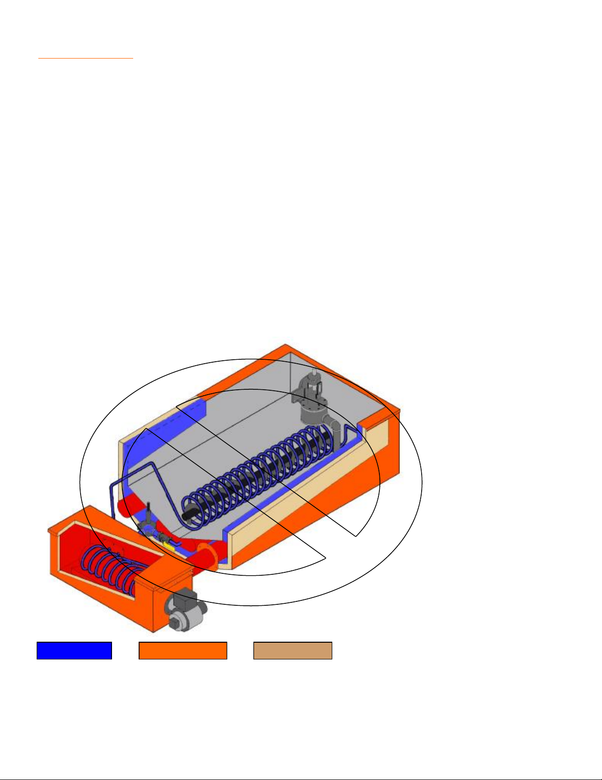
The OJK uses a tank surrounded by an oil jacket filled with heat transfer oil. The heat transfer
oil is heated by a diesel fired burner and is circulated in the oil jacket by a pump. In addition to
the oil jacket there is a coil surrounding the agitating auger in the tank. Heat transfer oil is
pumped through this coil to facilitate heating of the asphalt material. The temperature of the
product and the heat transfer oil is automatically maintained by electronic temperature con-
trols.
The heated asphalt is applied to the crack by an electrically heated hose and wand. The heat-
ing element in the hose and wand keep the product at working temperature thus eliminating
wand "freeze up". No cleanup or flushing of the wand and hose is required.
Power is supplied by a diesel engine. The engine drives a 24 volt alternator for the heated
hose and wand. It also drives a hydraulic pump that powers the heat transfer oil circulation
pump, product pump, agitating auger and the optional direct mounted 100 CFM rotary screw
air compressor.
Heat from Burner Heat Transfer Oil Insulation
9
DESCRIPTION Component Location
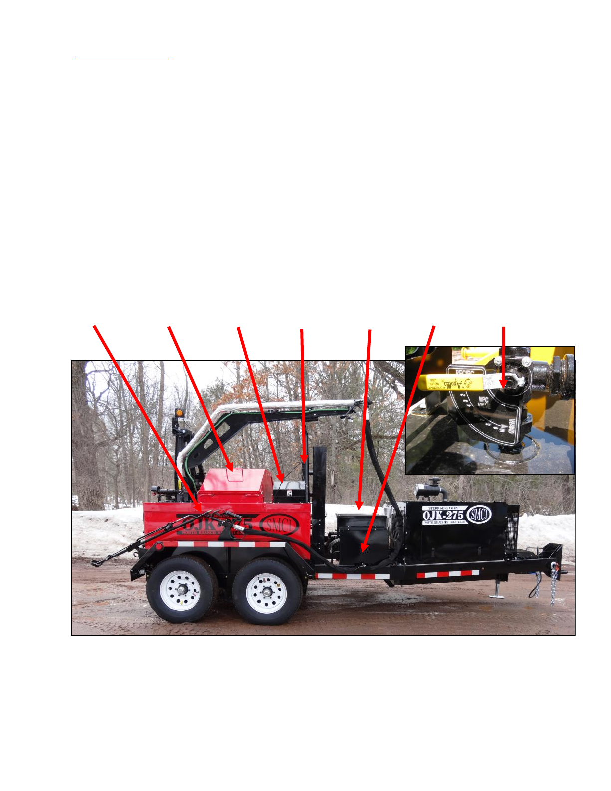
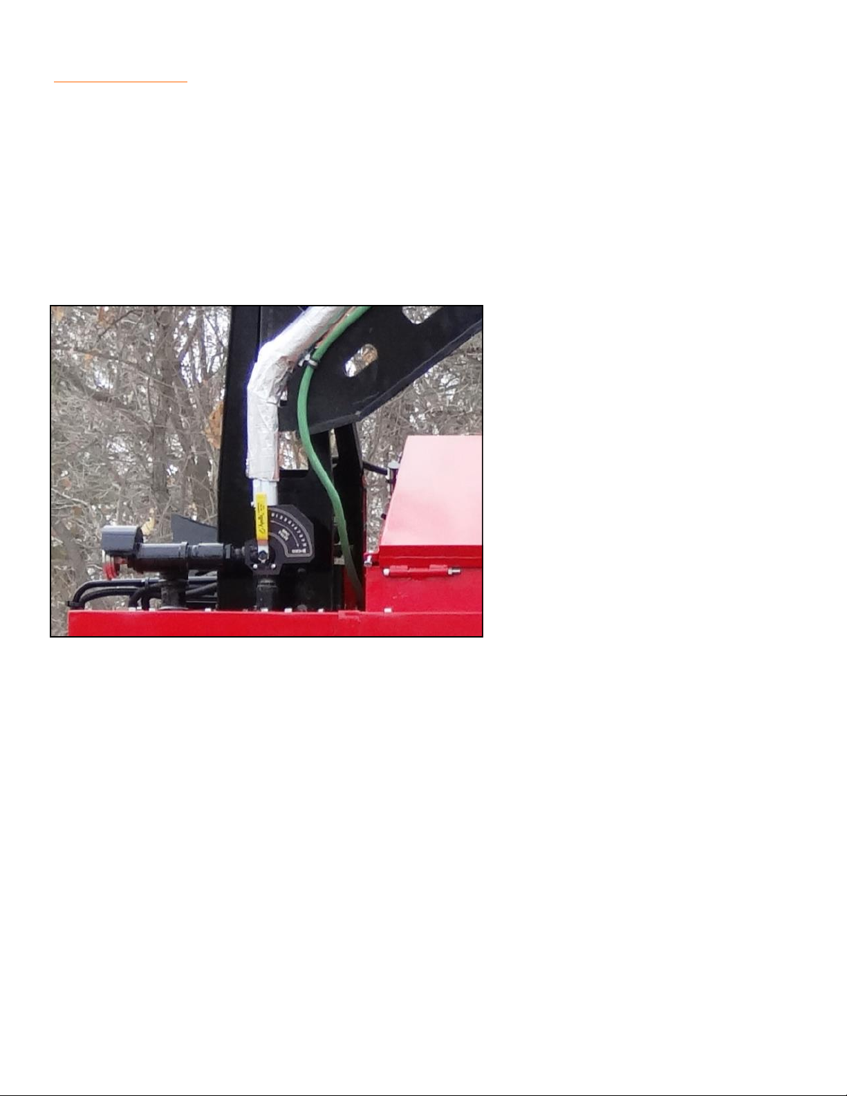
1. Wand Pressure Control (WPC) Valve — Controls the amount of pressure being applied to
the hose & wand when the pump saver system is not being used. Also allows the operator
to divert the flow of material back to tank for circulation, or to the wand for application to
the road surface.
2. Safety Loading Chute — Provides a "splash free" way of loading product into a hot tank.
3. Dip Stick / Fill Cap — Provides a way to check and fill the heat transfer oil tank.
4. Expansion Tank — Provides room for the heat transfer oil to expand and allows the oil to
cool. This creates a "cold seal" effect allowing safer operation at elevated oil tempera-
tures.
5. Heat Exchanger Chamber — Exchanges heat from the burner to the heat transfer oil.
6. Oil Pump Drive Motor — Drives the heat transfer oil circulation pump.
7. Wand and Hose — Provides a means of applying the product to the road surface.
1.
3.
2. 4. 5.
7. 6.
10
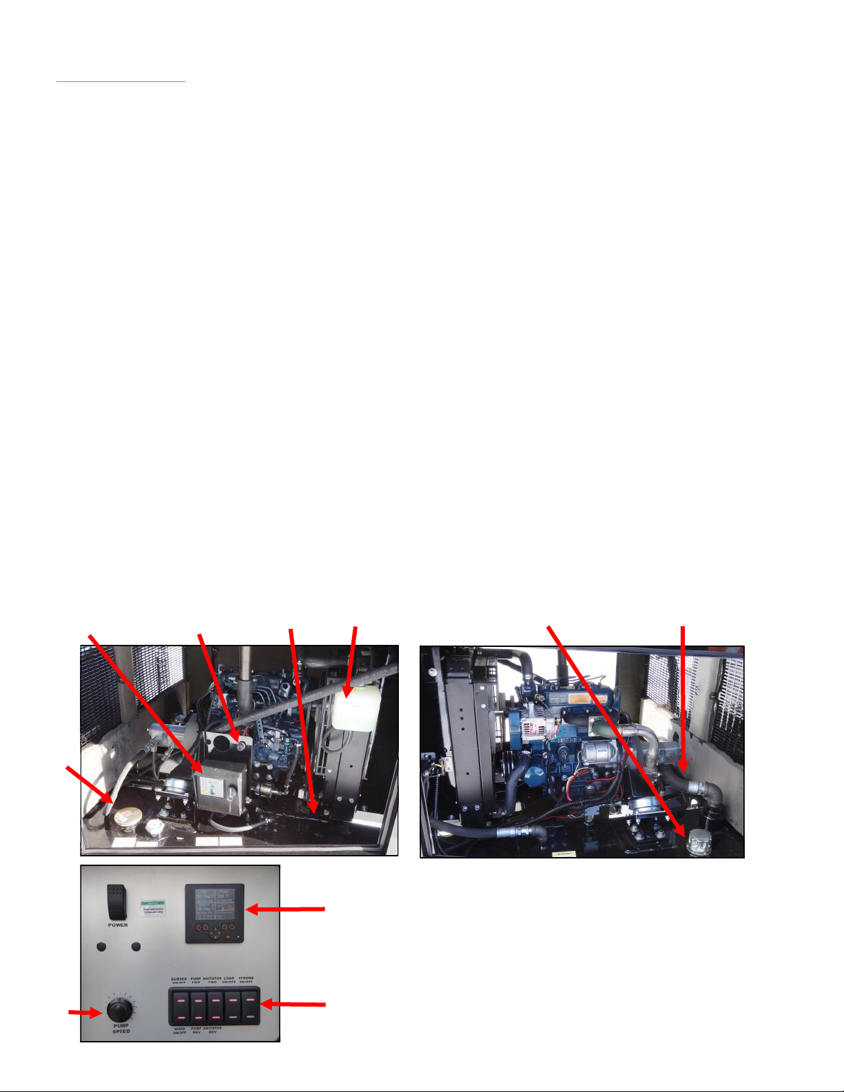
1. 24V Alternator — Provides electrical power to the wand and hose heating elements.
2. Engine Control Panel — Provides a means of controlling engine functions.
3. Engine Fuel Filter — Provides clean fuel to engine. (not shown)
4. Hydraulic Filter — Removes contaminates from the hydraulic system. (not shown)
5. Hydraulic Reservoir — Provides a 15 gallon capacity for the hydraulic system.
6. Fuel Tank and Gauge — Stores 20 gallons of diesel fuel to operate the burner and the
engine.
7. Product Pump Control — Allows the operator to start, stop, or reverse the rotation and
control the speed of the product pump.
8. Hydraulic Pump — Provides hydraulic power to the heat transfer oil circulation pump, au-
ger, and the product pump.
9. Radiator Reservoir– Used to fill the radiator.
10.Hydraulic Unloader– Unloads the hydraulic load on the engine for cold starts.
11.Automatic Temperature Controls for Burner, Oil and Wand Temperatures — Controls
burner and wand heating functions.
12.Operation Switches — Operates Burner On/Off, Wand On/Off, Auger Fw / Rev, Pump
Fw / Rev, Autoloader On/Off, and Strobe Light On/Off
6.
2. 1. 8.
7.
5.
9.
10.
11.
12.
DESCRIPTION Component Location

11
1. Wand Pressure Control (WPC) Valve — Controls the amount of pressure being applied to
the hose & wand when the pump saver system is not being used. Also allows the operator
to divert the flow of material back to tank for circulation, or to the wand for application to
the road surface.
2. Thermometer — Indicates the temperature of the material as it is pumped from the tank.
3. Circulating Flange — The wand is placed into this port allowing circulation through the
wand and back to tank.
4. Wand Rest — Holds the wand in position when circulating through the wand back to tank.
5. Thermostats — Digital display thermostats control the temperature of the heat transfer oil
and the product temperature.
6. Controller Warning Light — Will flash in the event of a burner malfunction or if burner inter-
lock is locked out.
7. Drive Motor — Hydraulic drive motor powers the agitating auger.
8. Electric Overnight Heaters — Maintains heat transfer oil temperature of approximately 150
to 200°F.
9. Draw off cock — Provides a means of draining tank or filling dispensing equipment.
10.Thermal Well — Contains temperature sensor for product temperature.
11. Heat Transfer Oil Level Plug — Allows easy check of oil level only when unit is cold.
1
2
3
4
5
9
78
11
10
6
DESCRIPTION Component Location

12
DESCRIPTION Heating System
Burner System:
The heating system is designed to burn diesel fuel and efficiently heat the transfer oil. The
heating system is equipped with constant ignition (flame-out protection) and automatic con-
trols to monitor the temperature of the heat transfer oil and the product temperature. Heat
transfer oil must be circulated through the heat exchanger whenever the burner is on. This
prevents the heat exchanger from overheating and causing damage to the equipment. Oper-
ation of the engine is required during the heating cycle to supply hydraulic pressure to the
heat transfer oil pump. The pump then circulates the heat transfer oil through the heat ex-
changer and the hot oil coil in the product tank.
WARNING: Operation of the burner without the engine running and oil circulating will cause
an overheat situation resulting in severe damage to the heat exchanger. Whenever the en-
gine is shutdown, the burner will also shutdown.
Agitator:
This unit is equipped with a hydraulically operated agitator with forward / reverse control. Op-
erating the agitator during the heating cycle will decrease the amount of time and energy
necessary to bring the product up to working temperature. The agitator should be turned on
as soon as the material melts sufficiently enough to allow the agitator to rotate usually
around 275°F.
Product Pump:
The Stepp OJK is equipped with a hydraulically operated product pump with "Pump & Re-
verse" control. In the "Pump" position, the pump delivers product from the tank, through the
hose, and to the wand for application to the road surface. In the "Reverse" position the pump
draws the product out of the product pump, plumbing, and WPC (wand pressure control)
valve to prevent freeze-up when the unit is shutdown. The product pump is mounted in the
tank allowing it to heat to the proper temperature along with the product, thus it is not neces-
sary to preheat the pump. The product pump should only be engaged when the product has
reached a temperature that will allow the product to flow through the pump and plumbing.

13
DESCRIPTION Controls
Stepp AKC Advanced Kettle Controls:
The Stepp OJK shall be equipped with the Stepp AKC Advanced Kettle Control, can buss
PLC control system. The AKC controller shall monitor and control all burner functions, pump-
ing and agitation controls, kettle interlock safety systems, autoloader controls and operations,
auger safety shutdown, and diagnostics for the burner control system. The AKC integrates all
burner and hydraulic controls into a simple easy to use control package.
The AKC control operates the automatic spark ignition and lights the burner with the flip of a
switch and includes flame-out protection to shut off the fuel supply if the flame is blown out.
The AKC control has an easy-to-adjust thermostat with a setting range from 0° - 550° F. A
large color display makes it easy to monitor the product temperature in the tank. Once the
operator sets the desired temperature, burner operation and temperature controls are fully
automated with this system. The AKC controls are to be located in a weather proof enclo-
sure. The enclosure shall have a transparent cover so the temperatures can be monitored
without the need to open the cover. The operator shall be able to read the product tempera-
tures when standing 6 feet from the machine.
The AKC Control Features are as follows:
Pump - on / off, adjust speed control
Auger - on / off, forward / reverse
Wand and Hose Heat - on / off.
Heat Transfer Oil - actual temperature and set temperature
Material - actual temperature and set temperature
Hose - actual temperature and set temperature
Pumping System Interlock - will not allow operator to start pump or auger until product and
hose have reached 275°F
Burner Control Diagnostics - turns warning light on when components fails
Burner Lock-out with Warning - warning light flashes until temperature is reached
US / Metric Conversion- user selectable US or metric temperature controls
User adjustable lock out settings
Pump speed indication
Optional Equipment:
Exact Flow Wand Control - controls pump speed from wand
Autoloader - on / off
Autoloader auto / manual - auto mode automatically dispenses a block into the kettle when
one is pumped through the wand
Pump Hour Meter - totalizes pump hours with autoloader option
Block Counter - totalizes the blocks used with autoloader option
Material Dispensed - totalizes gallons used with autoloader option
Strobe light - on / off
14
DESCRIPTION Wand Pressure Control Valve
CAUTION: Operators must understand the proper operation of the WPC valve located on the
top rear of the unit.
The purpose of this valve is to direct the flow of product either back to the tank (during start-
up to assist melting) or to the wand (during crack filling operations).
During normal operation the WPC valve will be in the “Wand” position and the flow of crack
sealant will be adjusted by the “Pump Speed” control located in the operators control box.
When finished for the day, the WPC valve will be returned to the “Recirculate” position and
the pump reversed to evacuate the plumbing.

15
DESCRIPTION Misc.
Heated Hose & Wand:
The application wand and hose are equipped with an internal heating element. The element is
powered by the 24 volt alternator run by the engine. This heating element prevents the prod-
uct from "freezing" in the hose and wand.
The electric wand heat control should be turned on 20 to 30 minutes before trying to pump
material through the hose and wand. This will allow time for the material to reliquefy in the
hose.
NOTE: It is recommended that you circulate the product back to the tank through the wand
circulating flange provided in the hood. This is to assure proper flow and temperature of the
material going though the wand.
Depending upon the volume of the material going through the wand and the outside tempera-
ture, it may not be necessary to run the heated wand all the time. Once flow is established
through the wand and circulating back to the tank, it is recommended that the electric heating
element be used only as required to maintain flow. This will help to extend the service life of
the components. If the flow is not adequate to maintain temperature in the hose and wand,
freeze up may occur. If this happens, simply turn the electric heating element on and allow
time for the material to remelt.
No cleanup is required with the electric wand, just shut the machine off as the product can be
remelted by activating the wand heat control. No additional flushing is required.
Overnight Heater (optional):
This feature will maintain the product from 150° to 200° F., saving startup time. The system
consists of two heating elements submerged in the heat transfer oil.
The heaters require 110V, 15 amp service each. The extension cords used must be the out-
door heavy duty type, grounded, and each rated for 1500 watt service.
CAUTION: Make sure to plug each heater into separate circuits or it may cause the breaker
to trip on your outlet.
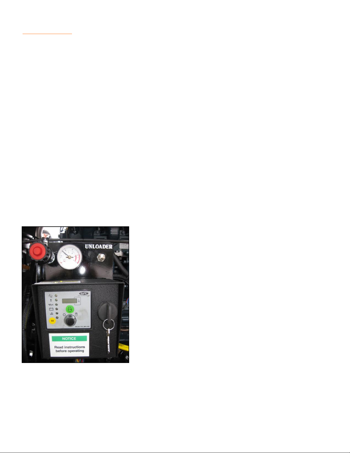
Digital Engine Management Controls:
The engine controls consist of a starter / glow plug button, an unloader switch to relieve the
hydraulic pressure for starting purposes (the deep sea control will also stop the engine in
case of low oil pressure or high coolant temperatures), and indicator lights for oil pressure,
coolant temperature, hour meter and volt meter. Optional equipment includes engine gauges.

16

17
OPERATIONS

18
OPERATIONS Basic Operations
Pre-start Checks:
The burner system is equipped with a safety interlock system that prevents the burner from
igniting unless the engine is running.
WARNING: This safety interlock must be tested each time before the engine is started. Fol-
low the steps below prior to engine start.
1. With engine OFF, turn the burner power switch ON, the burner and blower motor should
NOT operate. If the burner or blower motor runs there is a fault in the system, shut OFF
burner switch immediately. Contact a qualified service technician and correct the problem
before continuing.
2. Be sure the burner switch is in the OFF position.
3. Check the overall appearance of the unit inspecting for any obvious damage.
4. Check all fluid levels, the condition of the hot asphalt hose, and the 24 volt alternator belt
(refer to the daily maintenance schedule).

19
OPERATIONS Basic Operations
Transporting:
1. Shut off the burner and the engine.
2. Securely latch the loading chute and recirculating flange.
3. Secure the wand and hose assembly in the hanger.
4. Attach the unit to the towing vehicle being certain hitch is fully engaged, connect safety
chains, electrical connector, and breakaway switch (if equipped), retract the landing gear
and secure in the up position.
5. Check the condition and operation of the lights, tires, brakes, hitch, and safety chains.
Loading:
It is very important that the operator know the operating temperature and flash point of the
product being used. This information is available from the product manufacturer. Be sure the
thermostat is set at the recommended temperature.
Prior to adding product to the tank, ensure the compatibility of the product in the tank to that
being loaded. If products are not compatible the tank must be thoroughly drained and cleaned
before switching products.
Loading When Hot:
1. Open loading chute and place block of product in chute, close loading chute and product
will drop into tank. Open chute and repeat until product is at the desired level. Agitator will
automatically shut off when cover is open. Make sure to close the cover to start the agita-
tor and ensure that the material stays mixing.
2. Close loading chute but DO NOT latch, this will allow for emergency venting in case of a
“flash”.
20
Engine Starting:
NOTE: Be sure all pre-start checks are complete prior to starting engine.
1. Fill fuel tank.
2. Turn key switch to the ON (right) position.
3. Hold yellow glow plug button down for 30-60 seconds.
4. Press and hold the unloader button (this allows the engine to start with out hydraulic load
on the engine). Hold in for 1 - 3 minutes once the engine starts (in cold weather operation
you may need to hold in longer to allow engine to warm up before putting under load).
5. Press green start button to start engine.
6. If engine does not start on first try, turn key switch OFF and start the starting sequence
over.
5. Check to see that the heat transfer oil pump is rotating, if not investigate problem before
proceeding to heating operations.
6. For units equipped with optional air compressor, an adjustable throttle is provided (shown
in picture below). For units without the compressor, the engine is governed at the optimum
speed for operation of the kettle and no throttle cable is provided.
OPERATIONS Engine
This manual suits for next models
3
Table of contents
Other Stepp Industrial Equipment manuals


Popular Industrial Equipment manuals by other brands

Siemens
Siemens 3TL8 operating instructions

Bühler technologies
Bühler technologies ModbusRTU TC-MIDI Installation and operation instruction manual

ABB
ABB HT606820 Operation manual

Teac
Teac TU-BR-G Instructions for use

Siemens
Siemens 3VT9100-3HG10 operating instructions

Siemens
Siemens TNKM Series installation instructions


Lucent Technologies
Lucent Technologies Lineage 2000 SR Series product manual

Raycus
Raycus RFL-C6600S user guide

Milnor
Milnor PulseFlow 76028 G3 Installation and service

steute
steute RF I/O SW868-NET Mounting and wiring instructions

ABB
ABB HT603330 Operation manual

R.V.R. Elettronica
R.V.R. Elettronica PJ250-NV Technical manual