MONITOR
Alimentación: 13,5 V - - - 1,5A
Consumo: 20W en operación, 1W en reposo
CÁMARA
Alimentación: 12 V - - -
Consumo: 2W
Angulo de visión: 53°
Iluminación mínima: 0,1 lux a 30cm
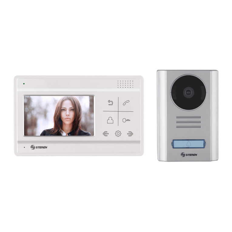
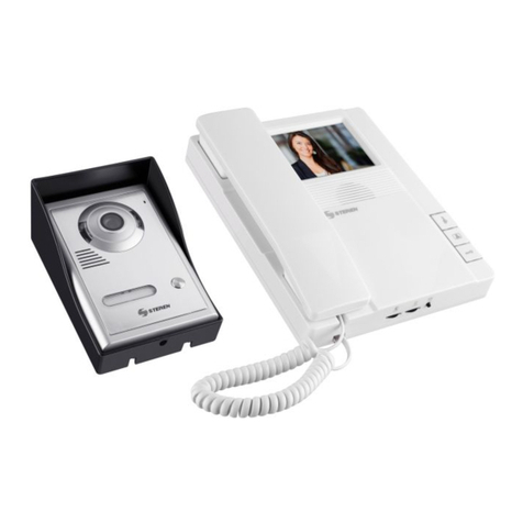
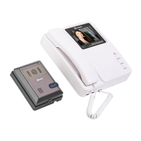
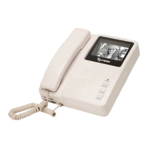
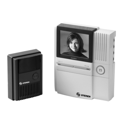
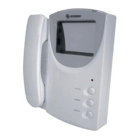
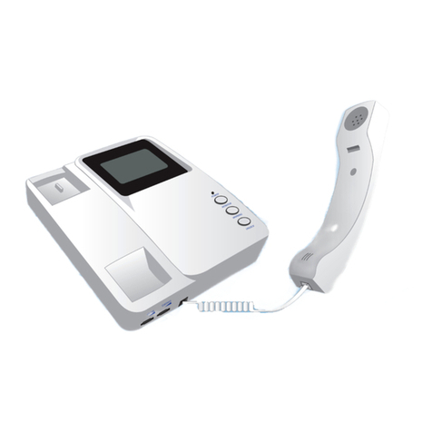
El sistema de intercomunicación con monitor de 4” blanco / negro y cámara de visión
nocturna, es perfecto para identificar quien toca a su puerta de día o de noche y
evitar ser sorprendido. Incluye una ranura para tarjetas SD, la cual almacena una
fotografía de la persona que está tocando el timbre. La cámara permite un ajuste de
la inclinación de hasta 30° adaptándose a cualquier muro, por medio de su placa
de fijación.
- Pantalla plana CRT de 10cm (4”), control de chapa eléctrica por medio de un botón,
apagado automático, cámara con visión nocturna infrarroja, cámara resistente a la
lluvia, sistema bi-direccional de conversación y captura instantánea de imagen.
SECCIÓN INTERNA
1. Cuando el visitante presione el botón de “llamada”, escuchará un timbre en
el equipo interior. La imagen del visitante se muestra de forma simultánea en la
pantalla y automáticamente se guarda una foto en la memoria SD.
2. Levante el auricular para hablar con la persona fuera de su casa / oficina. El
sistema se apagará después de que cuelgue. Si no contesta, el sistema se apagará
automáticamente después de 30 segundos.
3. Después de hablar con el visitante, presione el botón de apertura de cerradura si
desea que la puerta se abra automáticamente.
Para activar la cerradura eléctrica (no incluida) es necesario que el auricular esté
descolgado.
4. Si desea ver lo que ocurre afuera, presione el botón de monitor.
5. Mueva el botón de contraste para ajustar el nivel de contraste en la pantalla.
6. Ajuste el nivel de volumen de acuerdo a sus necesidades.
CÁMARA
1. Se recomienda que je la cámara a una altura de entre 1,45 y
1,60 m para un correcto monitoreo.
2. Mueva el interruptor de ajuste de la cámara hacia
arriba o abajo para que la cámara visualice un área
denida.
3. Coloque el cable de conexión (cable blanco con 4
hilos de colores en cada extremo) en la parte trasera
de la base de montaje de la cámara, conectando los siguientes colores:
4. Puede conectar los 2 cables (negro/rojo) a una
cerradura eléctrica (no incluida) para la apertura de puerta.
5. Fije la base de montaje de la
cámara a la altura deseada e
introduzca 2 tornillos hasta que
quede rmemente sujeta a la pared.
Por último, coloque la cámara en
la base y atornille hasta que quede
completamente ja.
CONVERTIDOR CA/CD
Alimentación:100-240V~ 50-60Hz 600mA
Salida: 13,5 V - - - 1,5A
CONSUMO
SECCIÓN EXTERNA
1. El visitante presiona el botón de “llamada” para
comunicarse con el interior.
2. El visitante puede hablar a través del micrófono.
3. El sistema de fotografía infrarroja puede mostrar una
imagen clara del visitante, incluso en la noche.
DESCARGAR FOTOS
1. Extraiga la tarjeta e insértela a un lector de tarjetas en su
computadora.
2. Busque la carpeta “DCIM”. En ella se encuentran
guardadas las fotos.
AJUSTAR FECHA/HORA
1.- Mantenga presionada la tecla PLAYBACK hasta que se muestre en pantalla la
fecha/hora parpadeando.
2.- Use PLAYBACK para seleccionar un valor, POWER para disminuirlo, UNLOCK
para aumentarlo.
3.- Para guardar y salir, mantenga presionada la tecla PLAYBACK hasta que se
desactive la pantalla. Si desea encender el equipo presione el botón POWER.
COMO REVISAR LAS FOTOGRAFÍAS EN EL INTERCOMUNICADOR
Deberá colgar el auricular e insertar la tarjeta SD en la ranura. Presione PLAYBACK
para encender el monitor y UNLOCK para cambiar la fotografía mostrada. Si desea
eliminar las capturas simplemente presione el botón MONITOR.
INTERCOMUNICADOR
Se recomienda que fije el intercomunicador a
una altura de 1,45 m a 1,6 m.
1. Fije la placa de metal utilizando
tornillos y taquetes a la altura deseada.
2. En el intercomunicador conecte el
extremo del cable de la cámara de acuerdo a
los colores mostrados en la tabla.
3. Sujete el intercomunicador en la base de
metal previamente instalada.
4. Conecte el cable de corriente a un contacto
eléctrico cercano al intercomunicador.
5. Inserte una tarjeta SD en la ranura
correspondiente.
INTERCOMUNICADOR COLOR DEL CABLE
1NEGRO
3BLANCO
4AMARILLO
5ROJO
DIAGRAMA DE CONEXIÓN
PARED
CÁMARA
CERRADURA ELÉCTRICAINTERCOMUNICADOR
ADAPTADOR
1
34
5
NO HAY IMAGEN EN EL INTERCOMUNICADOR
- Si la cámara recibe el rayo del sol directamente obtendrá una mala imagen, use una
de las dos piezas como se indica en los diagramas 1A (para cubrir) ó 2 (para dar un
ángulo de 45°) para evitar la exposición.
- Verifique si el contraste está muy bajo, de ser así ajuste el nivel con la perilla hasta
observar una mejor imagen.
-Lea la sección “INSTALACIÓN” y verifique haber realizado las conexiones correctas.
NO PUEDO CAPTURAR FOTOGRAFÍAS
Si observa el mensaje “NO CARD” cuando presiona el botón CALL, significa que no
ha colocado la tarjeta SD. En este caso inserte y presione firmemente la tarjeta en la
ranura del intercomunicador.
INTERCOMUNICADOR
CÁMARA
POWER
MONITOR
WARNING
UNLOCK
VOLUME
CONTRAST
Auricular
Altavoz
Pantalla
Cable de conexión
Indicador
de uso
Botón de
monitor
Reproducción
Botón
de apertura
Volumen Contraste
Ranura para
tarjeta SD
Micrófono
Infrarrojos
Lente de la
cámara
Altavoz Botón de
llamada
Ángulo
AV B+
AB CD
lower
upper
Consumo nominal: 250 Wh/día
Consumo en espera: 6,57 kWh/año
CONECTOR COLOR DEL
CABLE
ANEGRO
B BLANCO
C AMARILLO
DROJO
Producto: Intercomunicador B/N con cámara y ranura SD
Modelo: CCTV-045
Marca: Steren
PÓLIZA DE GARANTÍA
Esta póliza garantiza el producto por el término de un año en todas sus partes y mano de obra, contra cualquier defecto de fabricación y
funcionamiento, a partir de la fecha de entrega.
CONDICIONES
1.- Para hacer efectiva la garantía, presente ésta póliza y el producto, en donde fue adquirido o en Electrónica Steren S.A. de C.V.
2.- Electrónica Steren S.A de C.V. se compromete a reparar el producto en caso de estar defectuoso sin ningún cargo al consumidor. Los gastos de
transportación serán cubiertos por el proveedor.
3.- El tiempo de reparación en ningún caso será mayor a 30 días,contados a partir de la recepción del producto en cualquiera de los sitios donde
pueda hacerse efectiva la garantía.
4.- El lugar donde puede adquirir partes, componentes, consumibles y accesorios, así como hacer válida esta garantía es en cualquiera de las
direcciones mencionadas posteriormente.
ESTA PÓLIZA NO SE HARÁ EFECTIVA EN LOS SIGUIENTES CASOS:
1.- Cuando el producto ha sido utilizado en condiciones distintas a las normales.
2.- Cuando el producto no ha sido operado de acuerdo con el instructivo de uso.
3.- Cuando el producto ha sido alterado o reparado por personal no autorizado por Electrónica Steren S.A. de C.V.
El consumidor podrá solicitar que se haga efectiva la garantía ante la propia casa comercial donde adquirió el producto. Si la presente garantía
se extraviara, el consumidor puede recurrir a su proveedor para que le expida otra póliza de garantía, previa presentación de la nota de compra
o factura respectiva.
DATOS DEL DISTRIBUIDOR
Nombre del Distribuidor _________________________________________
Domicilio _____________________________________________________
Producto _____________________________________________________
Marca _______________________________________________________
Modelo ______________________________________________________
Número de serie _______________________________________________
Fecha de entrega ______________________________________________
ELECTRONICA STEREN S.A. DE C.V.
Camarones 112, Obrero Popular, 02840, México, D.F. RFC: EST850628-K51
STEREN PRODUCTO EMPACADO S.A. DE C.V.
Biólogo MaximIno Martínez No. 3408 Int. 2, 3 y 4, San Salvador Xochimanca,
México, D.F. 02870, RFC: SPE941215H43
ELECTRONICA STEREN DEL CENTRO, S.A. DE C.V.
Rep. del Salvador 20 A y B, Centro, 06000, México. D.F. RFC: ESC9610259N4
ELECTRONICA STEREN DE GUADALAJARA, S.A.
López Cotilla No. 51, Centro, 44100, Guadalajara, Jal. RFC: ESG810511HT6
ELECTRONICA STEREN DE MONTERREY, S.A.
Colón 130 Pte., Centro, 64000, Monterrey, N.L. RFC: ESM830202MF8
ELECTRONICA STEREN DE TIJUANA, S.A. de C.V.
Calle 2a, Juárez 7636, Centro, 22000, Tijuana, B.C.N. RFC: EST980909NU5
En caso de que su producto presente alguna falla, acuda
al centro de distribución más cercano a su domicilio y
en caso de tener alguna duda o pregunta por favor llame
a nuestro Centro de Atención a Clientes, en donde con
gusto le atenderemos en todo lo relacionado con
su producto Steren.
Centro de Atención a Clientes
01 800 500 9000
El diseño del producto y las especicaciones pueden cambiar sin previo aviso.
POWER
MONITOR
WARNING
UNLOCK
CALL
MIC
Antes de utilizar su nuevo producto Steren, lea este instructivo para evitar cualquier mal funcionamiento.
La información que se muestra en este manual es de referencia sobre
el producto. Debido a actualizaciones pueden existir diferencias.
Por favor, consulte nuestra página web (www.steren.com) para
obtener la versión más reciente del instructivo.
