manuals.online logo
Brands
  1. Home
  2. •
  3. Brands
  4. •
  5. Roger
  6. •
  7. Control System
  8. •
  9. Roger MCX16-UZ User manual

Roger MCX16-UZ User manual

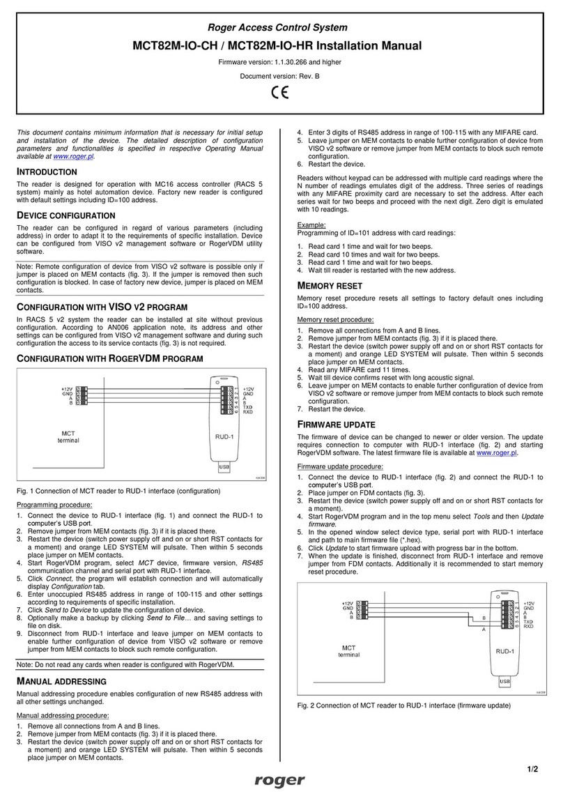
MCX16-UZ Installation Manual Rev.A 2023-10-10
1/2
Roger Access Control System
MCX16-UZ Installation Manual
Firmware version: 1.0.2.9 and newer
Document version: Rev. A
This document contains minimum information that is necessary for initial setup
and installation of the device. The detailed description of configuration
parameters and functionalities is specified in respective Operating manual
available at www.roger.pl.
INTRODUCTION
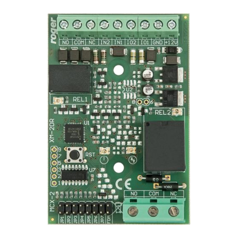
The MCX16-UZ I/O expander enables use of Clex (UHLMANN&ZACHER)
wireless locks as access terminals in RACS 5 system. MCX16-UZ operates as
hardware interface for communication of Clex locks with MC16 access controller.
The expander communicates with the MC16 controller using RS485-1 bus and
with Clex public online system using RS485-2 bus. MCX16-UZ offers its input
and output lines for use in RACS 5 system.
CONFIGURATION WITH ROGERVDM PROGRAM
Low level configuration with RogerVDM software enables to define basic
parameters of MCX16 expander.
Programming procedure:
1. Switch power supply off.
2. Short CLK and DTA lines.
3. Restore power supply (all LED flashing) and wait min. 5s.
4. Remove connection between CLK and DTA lines (LEDs stop flashing, LED8
is ON).
5. Start RogerVDM program, select MCX16-UZ v1.x device, the latest firmware
version and Ethernet communication channel.
6. Enter device IP address and communication key (by default respectively
192.168.0.81, admin).
7. Click Connect button, the program will establish connection and automatically
open configuration window.
8. Define RS485 address in range of 100-115 and if needed change IP address
and communication key.
9. Enable Clex locks and enter their serial numbers SW2-Version (8 ASCII
digits).
10. Optionally enter comments for CDI, OUT and PWR lock objects in order to
facilitate identification of locks during further configuration of the system.
11. Click Send to Device to update the configuration of device and disconnect by
selection of Device in the top menu and then Disconnect.
Note: The low level configuration of the expander cannot be modified with VISO
v2 software.
CONFIGURATION WITH VISO PROGRAM
High level configuration with VISO software enables to define the logic of
controller, expander and locks. More information on this subject is given in
AN056 application note.
MEMORY RESET
Memory reset procedure resets all settings to default ones and results in
192.168.0.81 IP address and ‘admin’communication key.
Memory reset procedure:
1. Disconnect power supply.
2. Press and remove memory card from expander.
3. Use memory card reader to connect the card to computer.
4. Delete CONFIG.INI file from the memory card.
5. Insert the memory card into expander socket.
6. Start RogerVDM and make low level configuration.
FIRMWARE UPDATE
New firmware can be uploaded to the controller via its memory card. The latest
firmware file is available at www.roger.pl.
Firmware update procedure:
1. Disconnect power supply.
2. Press and remove memory card from expander.
3. Use memory card reader to connect the card to computer.
4. Copy the new firmware (*.frg) to the memory card and rename it as FW.BUF.
5. Insert the memory card into expander socket.
6. Restore power supply and expander will automatically start the firmware
update process. During this process, which usually takes 10s, LED2 is ON
while LED3 is flashing.
7. Once the update is finished the FW.BUF file is automatically erased and
expander returns to service mode (LED8 is steady ON).
8. If needed, start RogerVDM program and make low level configuration.
Note: During the firmware update process, it is necessary to ensure continuous
and stable power supply for the device. If interrupted, the device may require
repair by Roger.
POWER SUPPLY
MCX16 expander can be supplied from 24VDC PSU, 12VDC PSU or 18VAC
transformer with minimal power output 20VA. In case of 12VDC power supply,
backup battery cannot be directly connected to the expander and in such case
backup power supply must be provided by 12VDC power supply unit. It is
recommended to install MCX16-UZ expander in ME-40-24V metal box which is
factory equipped with adequate PSU.
Fig. 1 MCX16 power supply
APPENDIX
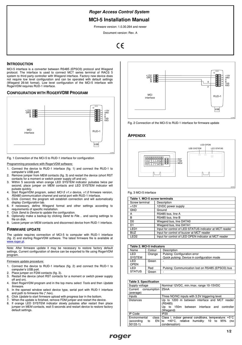
Table 1. Screw terminals
Name
Description
BAT+, BAT-
Backup battery
AC, AC
18VAC or 24VDC input power supply
AUX-, AUX+
12VDC/1.0 output power supply
TML-, TML+
12VDC/0.2A output power supply
IN1-IN8
Input lines
GND
Ground
OUT1-OUT6
15VDC/150mA transistor output lines
A1,B1
RS485 bus (MC16 controller)
CLK, DTA
Not used
A2,B2
RS485 bus (Clex FMS hub)
NO1, COM1, NC1
30V/1.5A DC/AC (REL1) relay
NO2, COM2, NC2
30V/1.5A DC/AC (REL2) relay
Table 2. LED indicators
Name
Description
LED1
Established connection with hub
LED2
-
LED3
ON: Low level configuration error
Pulsing: Communication lost with controller
LED4
RTC error
LED5
-
LED6
License error
LED7
ON: Backup battery error
Pulsing: Backup battery low level
LED8
ON: Service mode
Pulsing: Normal mode
Table 3. Specification
Supply voltage
17-22VAC, nominal 18VAC
11.5V-15VDC, nominal 12VDC
22-26VDC, nominal 24VDC
Backup battery
13.8V/7Ah, charging current approx. 300mA
Current consumption
100 mA for 18VAC (no loads on AUX/TML outputs)
MCX16-UZ Installation Manual Rev.A 2023-10-10
2/2
Inputs
Eight parametric inputs (IN1..IN3) internally connected
to the power supply plus through a 5.6kΩ resistor.
Approx. 3.5V triggering level for NO and NC inputs.
Relay outputs
Two relay outputs with single NO/NC contact 30V/1.5A
rated
Transistor outputs
Six open collector transistor outputs, 15VDC/150mA
rated. Max. total current sink by all outputs up to
3ADC.
Power supply outputs
Two power outputs: 12VDC/0.2A (TML) and 12VDC/1A
(AUX)
Distances
1200m for RS485
IP Code
n/a
Environmental class
(acc. to EN 50131-1)
Class I, indoor general conditions, temperature: +5°C
to +40°C, relative humidity: 10 to 95% (no
condensation)
Dimensions H x W x D
72 x 175 x 30 mm
Weight
approx. 200g
Fig. 2 Typical connection diagram
Notes:
•Up to 16 MCX16-UZ expanders can be connected to RS485 bus of MC16
controller but the total number of doors with CLEX locks (e.g. CX8172) cannot
exceed 16 and it depends on the version of MC16 controller.
•FSM hub can be supplied from standalone 12VDC PSU or from AUX/TML
outputs of MCX16-UZ expander or MC16 controller.
•The maximal RS485 bus length between controller and expander as well as
between expander and FSM hub equals to 1200m and it can be executed with
standard U/UTP cat. 5 cable.
•It is possible to install both MC16 controller and MCX16-UZ expander in the
same ME-40-24V metal box.
This symbol placed on a product or packaging indicates that the
product should not be disposed of with other wastes as this may
have a negative impact on the environment and health. The user is
obliged to deliver equipment to the designated collection points of
electric and electronic waste. For detailed information on recycling,
contact your local authorities, waste disposal company or point of
purchase. Separate collection and recycling of this type of waste
contributes to the protection of the natural resources and is safe to
health and the environment. Weight of the equipment is specified in
the document.
Contact:
Roger Sp. z o. o. sp. k.
82-400 Sztum
Gościszewo 59
Tel.: +48 55 272 0132
Fax: +48 55 272 0133
Tech. support: +48 55 267 0126
E-mail: support@roger.pl
Web: www.roger.pl

Other Roger Control System manuals

Roger PR611 User manual

Roger

Roger PR611 User manual

Roger IOS-1 User manual

Roger

Roger IOS-1 User manual

Roger MCT68ME-IO User manual

Roger

Roger MCT68ME-IO User manual

Roger RUD-3-DES User manual

Roger

Roger RUD-3-DES User manual

Roger PRT12MF-DES User manual

Roger

Roger PRT12MF-DES User manual

Roger MCT88M-IO User manual

Roger

Roger MCT88M-IO User manual

Roger MCT62E User manual

Roger

Roger MCT62E User manual

Roger MCT62E User manual

Roger

Roger MCT62E User manual

Roger MC16-PAC-2-KIT User manual

Roger

Roger MC16-PAC-2-KIT User manual

Roger OSR88M-IO User manual

Roger

Roger OSR88M-IO User manual

Roger B73/LTM Product manual

Roger

Roger B73/LTM Product manual

Roger B71/BCHP HW02 Product manual

Roger

Roger B71/BCHP HW02 Product manual

Roger H85/TDR Product manual

Roger

Roger H85/TDR Product manual

Roger MCT80M-BLE User manual

Roger

Roger MCT80M-BLE User manual

Roger MCT86M-IO-CH-HR User manual

Roger

Roger MCT86M-IO-CH-HR User manual

Roger MCI-2 User manual

Roger

Roger MCI-2 User manual

Roger MCT64E-IO User manual

Roger

Roger MCT64E-IO User manual

Roger PR411DR-SET User manual

Roger

Roger PR411DR-SET User manual

Roger CPR32-SE v2.0 User manual

Roger

Roger CPR32-SE v2.0 User manual

Roger MCX2-BRD User manual

Roger

Roger MCX2-BRD User manual

Roger MCT12M User manual

Roger

Roger MCT12M User manual

Roger MCT82-FK User manual

Roger

Roger MCT82-FK User manual

Roger MC16-PAC-2-KIT User manual

Roger

Roger MC16-PAC-2-KIT User manual

Roger MCX402-BRD User manual

Roger

Roger MCX402-BRD User manual

Popular Control System manuals by other brands

Siemens SINUMERIK 840D sl Commissioning manual

Siemens

Siemens SINUMERIK 840D sl Commissioning manual

Thermo King SR-2 SmartReefer2 Diagnostic manual

Thermo King

Thermo King SR-2 SmartReefer2 Diagnostic manual

Fancom Lumina 35 installation manual

Fancom

Fancom Lumina 35 installation manual

Festo Checkbox Compact CHB-C-X manual

Festo

Festo Checkbox Compact CHB-C-X manual

Klimor EVO -T Operation and maintenance manual

Klimor

Klimor EVO -T Operation and maintenance manual

Arjo Alpha Active 4 Instructions for use

Arjo

Arjo Alpha Active 4 Instructions for use

Crestron 4 Series product manual

Crestron

Crestron 4 Series product manual

Proteco BARRY user manual

Proteco

Proteco BARRY user manual

Ducasa Smart Command Tevolve Installation and operating manual

Ducasa

Ducasa Smart Command Tevolve Installation and operating manual

Norac UC5 Topcon X30 Operator's manual

Norac

Norac UC5 Topcon X30 Operator's manual

TECSYSTEM T119 Setup and Programming

TECSYSTEM

TECSYSTEM T119 Setup and Programming

Trane XL824 user guide

Trane

Trane XL824 user guide

DoorKing 1625 installation manual

DoorKing

DoorKing 1625 installation manual

Alera ALE-HT3SAB Assembly instructions

Alera

Alera ALE-HT3SAB Assembly instructions

Honeywell LYNX Touch L7000 Series Quick installation guide

Honeywell

Honeywell LYNX Touch L7000 Series Quick installation guide

Bosch Rexroth IndraControl XM21 operating instructions

Bosch

Bosch Rexroth IndraControl XM21 operating instructions

Extron electronics TouchLink user guide

Extron electronics

Extron electronics TouchLink user guide

TigerStop SAWGEAR installation guide

TigerStop

TigerStop SAWGEAR installation guide

manuals.online logo
manuals.online logoBrands
  • About & Mission
  • Contact us
  • Privacy Policy
  • Terms and Conditions

Copyright 2025 Manuals.Online. All Rights Reserved.