Steril-Aire 8100PVAB User manual
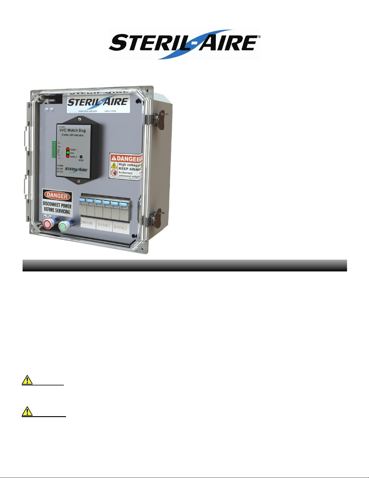
Installation and Operation Manual
UVC Controller
MODEL: 8100PVAB
100/120/208/240VAC
40A 9.6KW MAX
UL Approved
UL File Number E841436
Patents: 5,334,347/ 5,817,276/ 5,866,076/ 6,245,293/ 6,267,924/ 6,280,686/
6,313,470/ 6,372,186/ 6,423,882/ 6,500,267 /6,589,476/ 6,627,000/
6,783,578/7,140,749/ 7,282,728/ 7,459,694 & others pending
Made in the USA
NOTE: Read the entire manual
before starting the installation.
Improper installation, adjustments, alterations, service,
maintenance, or use can cause fire, electrical shock,
personal injury or property damage. Consult your supplier
or Steril-Aire for information or assistance.
DANGER, WARNING, or CAUTION are universally used
for overall safety. DANGER identifies the most serious
hazards which will result in severe personal injury or
death. WARNING signifies hazards which could result in
personal injury or death. CAUTION is used to identify
unsafe practices resulting in minor personal injury or
product and property damage.
WARNING: Before performing maintenance,
ensure unit is unplugged. Electrical shock can cause
death.
CAUTIONS:
Never expose eyes or skin to UVC light. Wear
gloves, face shield/glasses (per ANSI Z87.1) and
cover all exposed skin.
Do not touch EmitterTM glass without gloves.
Damage to Emitter may result. Oil from
fingerprints will permanently etch glass of
Emitter and weaken structure. Clean Emitter
using a Steril-Aire cleaning kit (included).
Isopropyl alcohol and a lint-free wipe may be
substituted.
UVC Emitters are fragile. Handle UVC Emitter
with care.
Voltages outside of the range designed for the
unit will void the warranty and do permanent
damage to the entire unit.
Emitters contain mercury. If an Emitter breaks,
clean and dispose of with the same care as a
fluorescent lamp.
UVC energy can damage non-metallic
components. Protect such components with UV
resistant material such as aluminum foil,
aluminum duct tape, metallic shields, etc.
The qualified installer or agency must use
factory kits and accessories when installing this
product.
IMPORTANT CONSIDERATIONS
Ensure mains at the power panel are turned off before connecting power to the controller. Apply any necessary
protection to assure that mains are not accidently turned on during the installation.
1) Make sure all the circuit breakers in the
controller are turned off.
2) Confirm the controller being installed is designed
for the line voltage and intended load(s). Check
labels, circuit breakers and fuse sizes before
installing.
3) Connect the door switch to two terminals on TB1
marked “DOOR”. The door switch is low voltage
24vac.
TB1 –Torque
AGW
In. Lb.
18-22
3.5
4) The enclosure meets type 4 approval for water
resistance. Use fittings that are consistent with
the environmental rating of the enclosure. Use
proper torque values.
5) When drilling holes, use caution as to not
damage internal components. Use the markers
inside the enclosure for safe drilling locations.
Ensure that holes are not close to each other
and away from the edge of the door to help
prevent cracking.
6) Remove the screws that secure the inner door.
This compartment should be opened by a
qualified electrician only!
7) Connect BMS. BMS includes Door and/or
watchdog.
8) Connect Bank-1 and Bank-2. Ensure that both
banks carry relatively equal load for proper
watchdog operation. Ensure proper circuit
breaker and grounding wire torque
9) Connect Mains. Ensure proper circuit breaker
and grounding wire torque
10) Torque the circuit breakers CB1, CB2 & CB3.
CB1, CB2 & CB3 - Torque
AGW
In. Lb.
3 to 12
13 to 17.5
11) Torque ground bar TB2.
TB2 –Torque
AGW
In. Lb.
4 to 6
45
8
40
10 to 14
35
12) Close inner door and secure the screws.
13) Turn on the mains at the power panel on.
14) Turn on the mains in the Simple Controller.
15) The RED stop light should be illuminated.
16) Turn on the Bank1 and Bank2 circuit breakers.
17) Close and latch the Simple Controller front door.
18) Press the Green Start Button.
19) The emitters should be illuminated.
1) If applicable, Connect Watchdog BMS relay to a BMS system.
Watchdog –Torque
AGW
In. Lb.
16-26
1.7
2) Reset the watchdog by press and hold the reset button until the green light is constant.
3) The following conditions will send an alarm to the BMS system:
a) If a bank LED is Red.
b) Power loss. No LED’s are light.
INSTALLATION
WATCHDOG

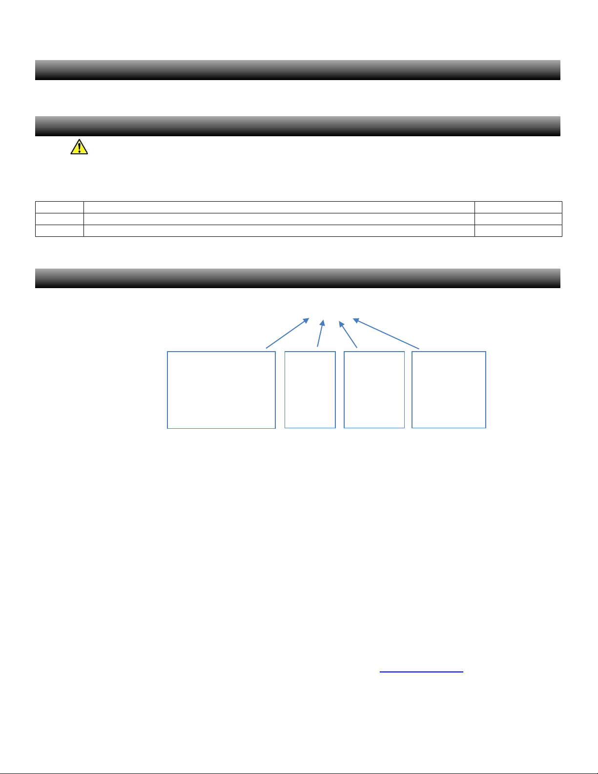
Connection/component Locations
Line output fuse, PN:80004125-500
Line output fuse, low
voltage circuit,
PN:80004115-1000
Door Switch Connection
TB2 Ground Bar
Circuit Breakers
Watchdog Reset
Display
Watchdog
connection to BMS
(dry contacts)
Door Switch Connection

READING THE DISPLAY
Normal Run: Indicates that
Emitters are lit and There are
no alarm conditions
Emitters Off: A flashing run light
Indicates that the emitters are
turned off.
Bank Faults: These alarms indicate that an
emitter or power supply may need attention.
Cycling the emitters power off/on or a reset will
clear the alarm.
Bank Over Current: Fast flashing bank lights indicates that one or more banks are drawing
more current than the watchdog was designed for.
Replace Emitters: Both bank lights flashing every second indicates that the emitters have reached
the end of their useful lifespan. The 9,000-hour timer runs only when power is applied to the
emitters. Replace with authentic Steril-Aire emitters for maximum output and lifespan. Blinks once
every second.
MENU DISPLAYS AND FUNCTIONS
Display a menu by clicking the reset button. Select the desired menu by clicking through the menus. If you missed your
menu, keep clicking until your menu is displayed again. If you wait long enough, the menu will time out and normal operation
will resume. Once the desired menu is displayed, press and hold the reset button until the menu display changes.
Menu 0: Reset Emitter Fault: Use the reset emitter fault by holding the reset button down or cycle
through the menu. A successful reset will be followed by a marque pattern of LED’s. This pattern
will repeat itself 8 times.
Menu 1: Report Run Hours: This is part of the 9,000-hour timer. Hold the reset button until the
green run LED starts to flash. Each flash of the LED indicated that 1,000-hours has expired. At
9,000-hours, the end of emitter life alarm will flash. This function will keep counting even after
9,000-hours has expired.
Menu 2: This menu is reserved and has no function at this time.
Menu 3: Reset 9,000 Hour Timer: This menu resets the runtime timer. It will clear the 9,000-hour
timer after emitters have been replaced by installing authentic Steril-Aire emitters for maximum
output and lifespan. Hold the reset button until the display normal run status.
Emitters Off.
No Alarm.
Bank 1 Off
Run Flashing
Bank 2 Off
Bank 1 Fault.
BMS Alarm
Bank 1 On
Run Off
Bank 2 Off
Bank 2 Fault.
BMS Alarm
Bank 1 Off
Run Off
Bank 2 On
Bank 1 & 2 Fault.
BMS Alarm
Bank 1 On
Run Off
Bank 2 On
Bank 1 & 2 Over Current.
BMS Alarm
Bank 1 Flashing
Run On
Bank 2 Flashing
Replace Emitters.
No Alarm
Bank 1 Blink
Run Blink
Bank 2 Blink
Menu 0
Reset
Bank 1 Off
Run Off
Bank 2 Off
Menu 1
Report Run Hours
Bank 1 On
Run Off
Bank 2 Off
Menu 2
Not Assigned
Bank 1 On
Run On
Bank 2 Off
Menu 3
Reset 9K timer
Bank 1 On
Run On
Bank 2 On
Normal Run.
No Alarm.
Bank 1 Off
Run On
Bank 2 Off
Emitters need to be replaced every 9000 hours. Use Genuine Steril-Aire Emitters to maintain design output. If a Steril-Aire
UVC Radiometer Kit is used, the Emitters should be replaced when the output falls below 50% of initial output.
Use Genuine Steril-Aire replacement parts. Parts in this device were certified by one or more safety
originations such as UL, CE... Replacement parts not intended for this device may cause equipment failure or damage.
Replacement Fuses:
Fuse
Description
Part#
F1 & F2
FUSE 0.5A 600VAC Type CC, For Line Input
80004125-500
F3
FUSE 1A 250VAC 3AB 3AG, For 24VAC
80004115-1000
___________________________________________________________________________________________________________
Thank you for choosing Steril-Aire, #1 “UVC for HVAC” solution provider worldwide. Please contact your local supplier or Steril-Aire
directly if we can provide any further information or service. Call 1-818-565-1128 or visit www.steril-aire.com. Your satisfaction is very
important to us.
The health aspects associated with the use of this product and its ability to aid in disinfection of environment air have not been
investigated by UL. © 2017 Steril-Aire, Inc. All rights reserved. 1385
MAINTENANCE
SPARE OR REPLACEMENT PARTS
Controller Part Number Options
8100PVAB
Full Amps
3 = 10A
5 = 20A
6 = 30A
7 = 40A
VOLTS
3 = 100
4 = 120
5 = 208
6 = 240
PHASE
1 = SINGLE PHASE
2 = DOUBLE PHASE
Branch Amps
2 = 5A
3 = 10A
5 = 20A
6 = 30A
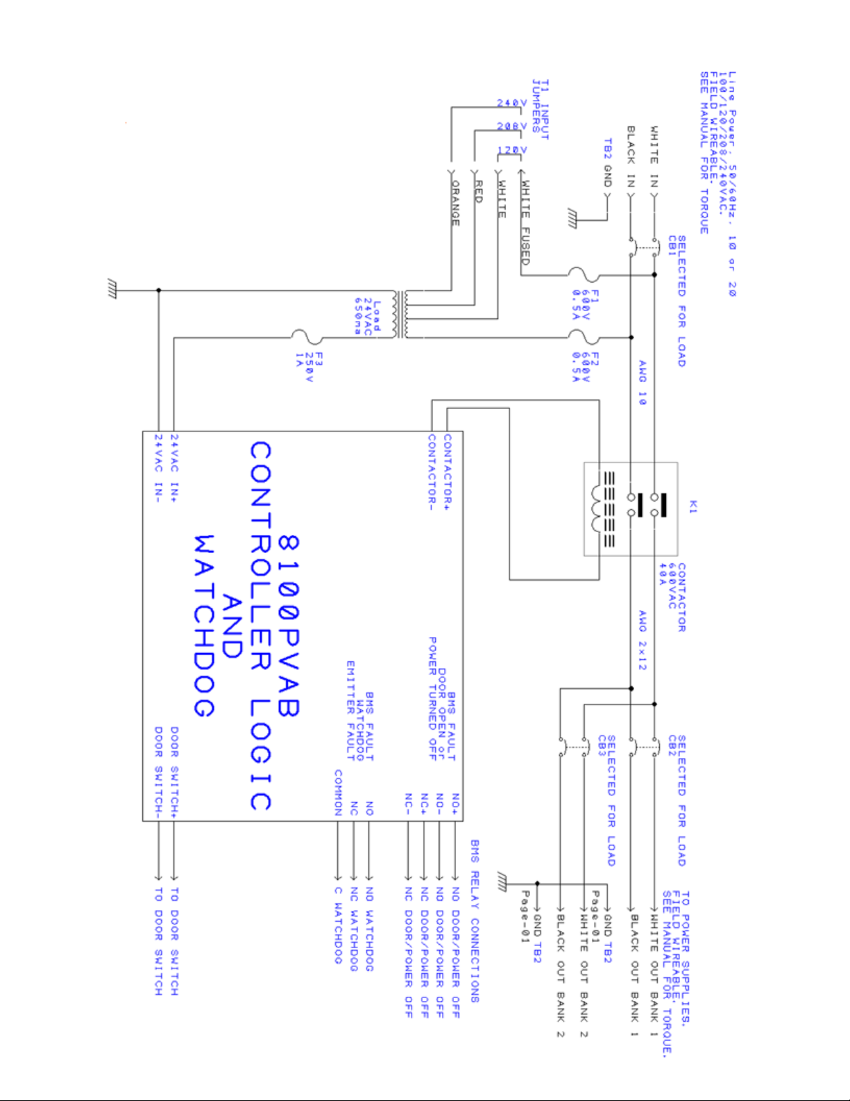
Table of contents
Other Steril-Aire Control System manuals


Popular Control System manuals by other brands

DAVIS TECHNOLOGIES
DAVIS TECHNOLOGIES TC-3 Series instructions

Wilo
Wilo Wilo-Control SC-Fire Electric A2P Installation and operating instructions

Tion
Tion MagicAir Base Station user manual

Espa
Espa PRESSDRIVE instruction manual

Electrolux
Electrolux EWM 1000 PLUS Service manual

Abicor Binzel
Abicor Binzel EWR 2 Original operating instructions


Fagor
Fagor CNC 8060 Users Quick Reference

RKC INSTRUMENT
RKC INSTRUMENT SR Mini System Supplementary information

Key Digital
Key Digital FATCAT Series Setup guide

illumicare
illumicare Merlin operating instructions

PS Engineering
PS Engineering PAC45 System With MultiTalker Pilot's guide and operation manual

CYP
CYP CVW-9000W Operation manual