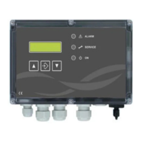
Steril-Aire UVC Controller II User manual

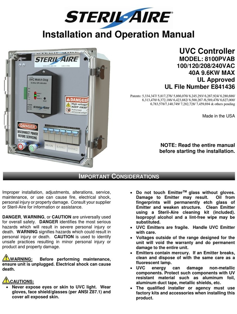
UVC Controller II
Installation and Operation Manual
Patents:
5,334,347/ 5,817,276/ 5,866,076/ 6,245,293/ 6,267,924/ 6,280,686/
6,313,470/ 6,372,186/ 6,423,882/ 6,500,267 /6,589,476/6,627,000/
6,783,578/7,140,749/ 7,282,728/ 7,459,694 & others pending
Made in the USA
NOTE: Read the entire manual
before starting the installation.
Improper installation, adjustments, alterations, service,
maintenance, or use can cause fire, electrical shock,
personal injury or property damage. Consult your supplier
or Steril-Aire for information or assistance.
DANGER, WARNING, or CAUTION are universally used
for overall safety. DANGER identifies the most serious
hazards which will result in severe personal injury or
death. WARNING signifies hazards which could result in
personal injury or death. CAUTION is used to identify
unsafe practices resulting in minor personal injury or
product and property damage.
WARNING: Before performing maintenance,
ensure unit is unplugged. Electrical shock can cause
death.
CAUTIONS:
•Never expose eyes or skin to UVC light. Wear
gloves, face shield/glasses (per ANSI Z87.1) and
cover all exposed skin.
•Do not touch EmitterTM glass without gloves.
Damage to Emitter may result. Oil from
fingerprints will permanently etch glass of
Emitter and weaken structure. Clean Emitter
using a Steril-Aire cleaning kit (included).
Isopropyl alcohol and a lint-free wipe may be
substituted.
•UVC Emitters are fragile. Handle UVC Emitter
with care.
•Voltages outside of the range designed for the
unit will void the warranty and do permanent
damage to the entire unit.
•Emitters contain mercury. If an Emitter breaks,
clean and dispose of with the same care as a
fluorescent lamp.
•UVC energy can damage non-metallic
components. Protect such components with UV
resistant material such as aluminum foil,
aluminum duct tape, metallic shields, etc.
•The qualified installer or agency must use
factory kits and accessories when installing this
product.
IMPORTANT CONSIDERATIONS
MODEL: 8102PVAB
100/120/208/240/277VAC
40A 9.6KW MAX
UL Approved
UL File Number E841436

Ensure mains at the power panel are turned off before connecting power to the controller. Apply any necessary
protection to assure that mains are not accidently turned on during the installation.
1) Caution use marked areas on the inside of the
enclosure for safe drilling locations. To prevent
cracking, ensure that holes are not close to each
other.
3) Make sure the controller is designed for the line
voltage and intended load. Check labels, circuit
breakers and fuse sizes before installing.
4) Make sure all the circuit breakers in the
controller are turned off.
5) Remove the 2 screws that secure the inner door.
This compartment should be opened by a
qualified electrician only!
6) Connect the door switch to the two terminals on
TB1 marked “DOOR”. The door switch is class 2
low voltage.
TB1
AGW
16-24
7) Connect BMS. BMS includes Door, Emitters and
Watchdog.
8) Connect Bank-1 and Bank-2 Loads. Ensure that
both banks carry relatively equal load for proper
watchdog operation. Ensure proper circuit
breaker and grounding wire torque
9) Connect Mains. Ensure proper circuit breaker
and grounding wire torque
10) Torque the circuit breakers CB1, CB2 & CB3.
CB1, CB2 & CB3 - Torque
AGW
In. Lb.
3 to 12
13 to 17.5
11) Torque ground bar TB2.
TB2 –Torque
AGW
In. Lb.
4 to 6
45
8
40
10 to 14
35
12) Close inner door and secure the screws.
13) Turn on the mains at the power panel on.
14) Turn on the mains in the UVC Controller.
15) The RED stop light should be illuminated.
16) Turn on the Bank1 and Bank2 circuit breakers.
17) Close and latch the Simple Controller front door.
18) Press the Green Start Button.
19) The emitters should be illuminated.
The current loop has an isolated 12VDC power source, no need for an external power supply. Line resistance can vary
from 0 to 200 ohms. Isolation is rated at 1.5KV. The 4-20ma current loop output represents 0-50A.
Calculate Amps to current loop: (Amps/3.125) + 4 = ma
Calculate Current loop to Amps: (ma –4) x 3.125 = Amps
Example using 40A: (40A/3.125) + 4 = 16.8ma
All solid state relays are normally opened, 60v AC/DC Max, 150Ma Max, 16 ohms Max closed, 1.5KV isolation. If the UVC
Controller loses power, contacts default to closed (alarm condition).
INSTALLATION
BMS 4-20MA CURRENT LOOP
BMS SOLID STATE CONTACTS (DOOR OPEN,EMITTERS OFF,FAULT)
2) This enclosure meets type 4 approval and IP67
criteria for water resistance. Use fittings that are
consistent with the environmental rating of the
enclosure. Use proper torque values on fittings.

Connection/Component Locations
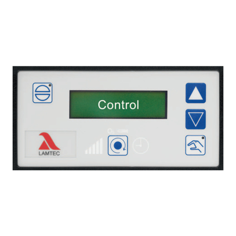
Menu/Select Button
Display
Menus & Status
QR Barcode
Link to Watchdog
Manual
F1 & F2 0.5A 600V
PN:80004125-500
TB2 Neutral/Ground
F3 1.25A 250V
80004127
Circuit Breakers
Remote Control &
BMS Connections

Home Menu: Displays Company name, Model number & Software revision.
Displays for 5 seconds on power up then changes to default menu.
The last menu viewed is saved as the default after 1 hour.
Status Menu: Indicates global system status.
Emitter power OFF, BUSY and ON. FAULT count and Total current.
Red indicates a fault condition. Press and hold button to clear faults.
Amps Menu: Indicates total current, bank1 and bank2 current.
Faults Menu: Faults count for banks 1 & 2.
Red indicates a fault condition. Press and hold button to clear faults.
Any faults will close the BMS alarm relay
Count Menu: Lamp counts how many times the Emitters have been ignited.
Power counts the number of times the Watchdog has been powered up.
Press and hold button to clear counts.
Timer Menu: Emitter end of life count down and total run hours.
Yellow indicates Emitters need to be ordered, 672 hours or 4 weeks remaining.
Red indicates Emitters have expired, replace emitters.
After replacing Emitters, Press and hold button to clear 9K count.
Order Menu: The order menu will popup when there is 672 hours of Emitter life remaining.
Yellow indicates Emitters need to be ordered, 672 hours or 4 weeks. remaining.
It is visible only when emitters need to be ordered.
Replace Menu: The Replace menu will popup when 0 hours, End of life is reached.
Red indicates Emitters need to be replaced.
The BMS alarm relay is closed.
AMPS BANK1 BANK2
37.8 18.6 19.2
FAULTS BANK1 BANK2
0 0 0
COUNT LAMP POWER
25 1
TIMERS 9K RUN HRS
523 1836
ORDER EMITTERS!
REPLACE IN 4 WEEKS
REPLACE EMITTERS!
INSTALL NEW EMITTERS
STERIL-AIRE
UVC CONTROLLER R1.00
STATUS FAULTS AMPS
ON 0 37.8
MENUS

Emitters need to be replaced every 9000 hours. Use Genuine Steril-Aire Emitters to maintain design output. If a Steril-Aire
UVC Radiometer Kit is used, the Emitters should be replaced when the output falls below 50% of initial output.
Always use Genuine Steril-Aire replacement parts. Parts in this device were certified by one or more safety
originations such as UL, CE... Replacement parts not intended for this device may cause equipment failure or damage.
Replacement Fuses:
Fuse
Description
Part#
F1 & F2
FUSE 0.5A 600VAC Type CC, For Line Input
80004125-500
F3
FUSE GLASS 1.25A 250VAC 5X20MM, For 24VAC
80004127-1250
MAINTENANCE
SPARE OR REPLACEMENT PARTS
Controller Part Number Options
810WPVAB
Full Amps
0 = 4A
1 = 6A
3 = 10A
O= 16A
5 = 20A
6 = 30A
S = 32A
7 = 40A
U= 50A
Branch Amps
E = 2A
F = 3A
2 = 5A
J = 8A
3 = 10A
4 = 15A
O= 16A
5 = 20A
Q= 25A
Phase
1 = SINGLE
2 = DOUBLE
Volts
3 = 100
4 = 120
5 = 208
6 = 240
7 = 277
Options
0 = Legacy Watchdog
2 = UVC Controller II
3 = UVC Controller III
NOTE: Circuit breakers need to be rated 125% of its expected load. If your load is 16.7A, then your circuit breaker needs to handle
22A. A 20A circuit breaker is to small, you will need a 30A circuit breaker.
Formula: Load amps x 1.25 = minimum circuit breaker size. 16.7A x 1.25 = 22A
___________________________________________________________________________________________________________
Thank you for choosing Steril-Aire, #1 “UVC for HVAC” solution provider worldwide. Please contact your local supplier or Steril-Aire
directly if we can provide any further information or service. Call 1-818-565-1128 or visit www.steril-aire.com. Your satisfaction is
very important to us.
The health aspects associated with the use of this product and its ability to aid in disinfection of environment air have not been
investigated by UL. © 2019 Steril-Aire, Inc. All rights reserved. Part #: 1146A
This manual suits for next models
1
Table of contents
Other Steril-Aire Control System manuals
Popular Control System manuals by other brands

btsr
btsr SMART 3000TW operating manual

Stanley
Stanley GUARD STST1-79226 manual

Certified Cirus Control Systems
Certified Cirus Control Systems Single Channel Motor Control Operation manual

Danfoss
Danfoss ADAP-KOOL AK-SM 800 Service guide

Lennox
Lennox Harmony III Homeowner's manual

Rotel
Rotel RR-700 owner's manual