StewMac FAN TREMOLO Manual

FAN TREMOLO
PEDAL KIT
INSTRUCTION GUIDE
.22 J63
1J63
.1J63
IN GND SW OUT
FROM
VINTAGE
WARBLE
TO CHOPPY
HELICOPTER
LIKE SOUNDS,
this one tremolo can do it all. With three adjustable
speed ranges, this pedal runs the gamut from
slow swamp like pulses to speedy envelope-like
weirdness.
PARTS LIST
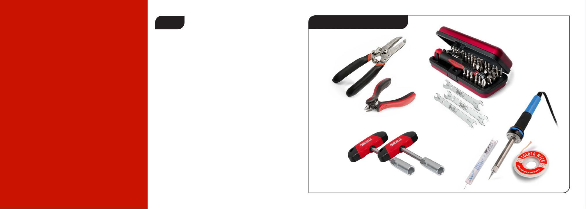
TOOLS AND SUPPLIES REQUIRED
REQUIRED
POWER
This pedal requires a standard 9V DC center-
negative power supply (not included) and
consumes less than 100mA. There’s no battery
option. Soldering Iron #0502
Solder Wick #0504
Solder #0505
Wire Cutter #1607
Wire Stripper #1606
Guitar Nutdrivers #5890
Guitar Tech Screwdriver
and Wrench Set #3696
Resistor values are indicated by colored bands, read from left to right. The rst
color in the code is usually the one painted closest to a lead wire. When a gold
or silver band is present, it’s always one of the last colors in the code.
Brown Black Black Yellow Brown
Red Red Black Red Brown
Red Red Black Brown Brown
Red Purple Black Red Brown
Brown Red Black Red Brown
Yellow Purple Black Red Brown
Red Red Black Orange Brown
1M resistor (1) #7367
22K resistor (1) #7379
2.2K resistor (2) #7376
27K resistor (1) #7398
12K resistor (1) #7392
47K resistor (2) #7369
220K resistor (1) #7381
Yellow Purple Black Black Brown
470Ω resistor (2) #7355
Yellow Purple Black Brown Brown
4.7K resistor (1) #7359
Brown Black Black Black Brown
100Ω resistor (1) #7352
PARTS LIST
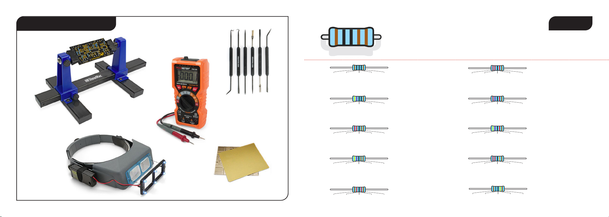
TOOLS AND SUPPLIES HELPFUL
*Not pictured:
Clear silicone adhesive and spray nish
PC Board Holder #0500
Magnifying glass or
OptiVISOR #1685
Soldering Aids #0521
Multimeter #3607
3M Gold Fre-Cut
Sandpaper #5097

220nF capacitor (1)
#7305
100nF capacitor (1)
#7304
10µF capacitor (1)
#7338
100µF capacitor (2)
#7312
10uF
1µF capacitor (2)
#7337
1uF
100uF
2.2µF capacitor (2)
#7315
2.2uF
4.7µF capacitor (1)
#7316
4.7uF
1N5817 rectier diode (1)
#7522
.22J63
1µF capacitor (1)
#7308
1J63
1uF
10uF
.1J63
5mm white LED (1)
#7422
PARTS LIST CONT
3PDT latching footswitch (1)
#1611
3-way toggle switch (1)
#7465
B10K linear taper pot (1)
#7532
B100K linear taper pot (2)
#7453
24" of lead wire (1)
#5960
Adhesive foam tape square (4)
#7560
Control knob (3)
#7501
5mm LED mounting bezel (1)
#7432
PF5102 transistor (1)
#7518
2N5089 transistor (1)
#7514
FKH09
PF
5102
CEN
2N5
089
2N6027 transistor (1)
#7515
2N
6027
C45
2.1mm DC power connector (1)
#7468
PARTS LIST CONT
D
E
P
T
H
R
A
T
E
132
L
E
V
E
L
1/4" mono jack (2)
#4652
Circuit Board (1)
StickerSheet (1)
Pre-drilled enclosure (1)
Breakout Board (1)
IN GND SW OUT
PARTS LIST CONT SOLDERING MORE HELPFUL
SOLDERING TIPS
AND TRICKS
•Keep your soldering tip
clean by wiping it often
on a damp sponge.
• Also keep it tinned by
occasionally melting
a little solder onto it.
•Don’t blow on the
hot solder or touch
anything until the joint
has cooled completely.
A good solder joint
is shiny—a sign that
it was left to cool
undisturbed.
• Plan so each joint is
only soldered once.
Resoldered joints are
messy and more likely
to fail.
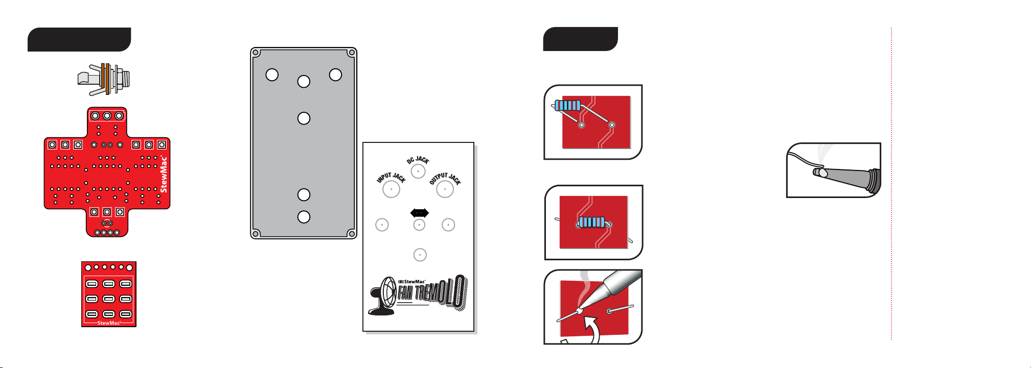
The solder joints you’ll make on the circuit boards are very
small, and too much heat can damage the board. The idea is to make joints
quickly, without scorching the eyelets.
1. Hold components in place for soldering by
threading the leads through the board and bending
them apart on the reverse side. You will be making
your solder joints on the reverse side of the board.
2. Melt a small amount of
solder onto the tip of
the iron (“tinning”the iron).
3. Insert the tip into the eyelet and let it heat for 4-5
seconds before touching it with solder. This heats the
contact enough for the solder to ow nicely without
damage. Feed the solder to the eyelet, not the iron,
and you don’t need much solder, just enough to ll
the eyelet. Keep the iron on the connection for a
second longer; this pause gives time for all of the ux
to cook out of the joint. After the joint has cooled,
trim away the excess lead wire.
Resistor values are indicated by colored bands, read
from left to right. The rst color in the code is usually
the one painted closest to a lead wire. When a gold
or silver band is present, it’s always one of the last
colors in the code. If you’re having trouble reading
the color bands, try using a multimeter to read a
resistor’s value. Just set your multimeter to ohms and
connect the test leads on each side of the resistor.
A number of dierent components are used to make
an eects pedal. The ones used in this pedal are
resistors, capacitors, diodes, and integrated circuits.
RESISTORS
Resistors are used in electrical circuits to direct
or reduce current ow and adjust signal levels.
In layman’s terms a resistor does exactly that,
resists the ow of current. The value of the resistor
determines how much eect the resistor will have
on the ow of electrons.
A resistor’s value—the amount of resistance it
creates—is rated in ohms (). Larger ohm values
mean more resistance. For example, a 100
resistor creates ten times as much resistance
as a 10 resistor.
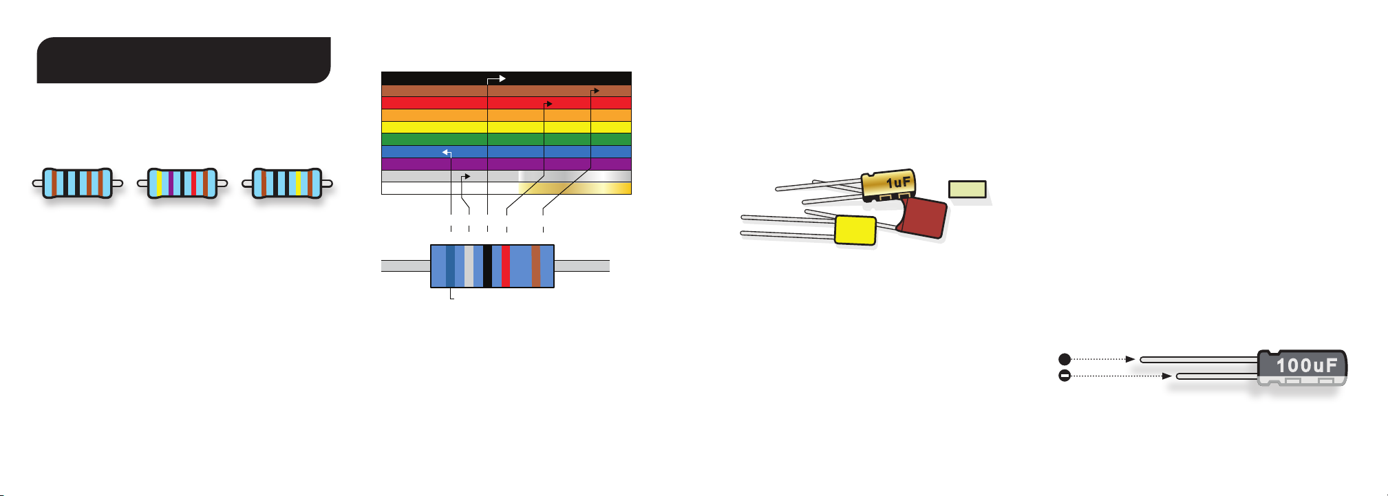
UNDERSTANDING ELECTRONIC
COMPONENTS
Band 1 Band 2 Band 3 Band 4 Band 4
1st Digit 2nd Digit 3rd Digit Multiplier Tolerance
6 8 x100 +/- 1%
68K +/- 1%
K=1,000
Blue
Read this band rst (closest to an end)
Gray Black Red Brown
BLACK 0 0 0 1
BROWN 1 1 1 10 +/- 1%
RED 2 2 2 100 +/- 2%
ORANGE 3 3 3 1,000
YELLOW 4 4 4 10,000
GREEN 5 5 5 100,000 +/- .5%
BLUE 6 6 6 1,000,000 +/- .25%
VIOLET 7 7 7 10M +/- .1%
GRAY 8 8 8 .01 SILVER
WHITE 9 9 9 .1 GOLD
0
Resistors and capacitors may also be referred to with
shorthand notation on the printed circuit board
when there is a decimal in the value. For example,
the place on the board for the 4.7K resistor will read
4K7 and the spot for a 2.2nF capacitor will read 2n2.
This is done to save space on the board and make
the labels as clear as possible.
Some capacitors have polarity and some don’t.
It’s extremely important to install polarized caps
correctly in a circuit. The negative lead will often
be indicated by a band of arrows pointing to the
negative lead and will be shorter than the positive
lead. The positive lead of an electrolytic cap will be
longer and won’t have any arrows pointing to it.
Installing capacitors with the polarity backwards will
make the circuit malfunction and quickly destroy the
capacitor— even causing it to explode.
CAPACITORS
The two main uses of capacitors are to store
electricity and to block the ow of DC current.
Capacitor values are typically printed on the
component. The key values with caps are their
voltage and capacitance.
The voltage spec for a cap refers to how much DC
voltage it can handle at any given time. If this rating
is exceeded, the capacitor will fail.
Capacitance, measured in farads, refers to how
much electricity a capacitor can hold. One farad (1F)
would be much too large for use in a pedal. Caps
for pedals are rated between millionths of a farad,
called microfarads (F), billionths of a farad, called
nanofarads (nF), or trillionths of a farad: picofarads
(pF). .001μF = 1nF = 1,000pF.
101J
100V
102J
1u F
.1J63
++
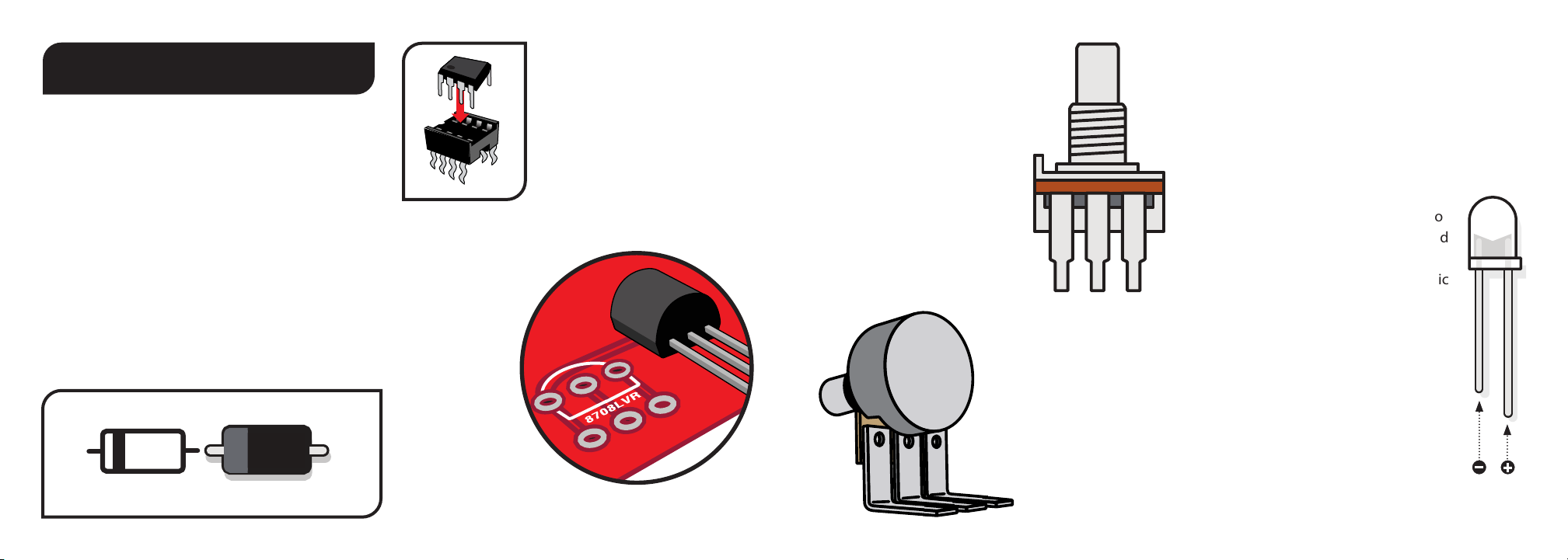
INTEGRATED CIRCUITS
Integrated circuits are complex,
tiny, self-contained collections
of components that contain
a complete circuit. Op-amps,
audio processors, and linear
voltage regulators are three
kinds of integrated circuits.
TRANSISTORS
Transistors are
used to amplify
electrical signals.
The have a at
side and a round
side. The location
on the circuit
board also has a
round side and a at
side. Match the orientation
of the component to this outline.
UNDERSTANDING ELECTRONIC
COMPONENTS
DIODES
Diodes are used where you want electricity to ow
in only one direction, such as power rectication,
and also to limit how much current can ow, to
create “clipping” distortion.
Diodes are also polarized, so they need to be
installed in the correct orientation. The stripe
around one end marks the negative (minus) lead of
the diode. On the circuit board, the printed outline
of the diodes also shows this stripe. Install each
diode so that its stripe matches the direction shown
on the circuit board.
2n2J630
TL072
PT2399
PT2399
PT2399
PT2399
echo audio
processor (1) #7490
TL072CP TL072CP
low noise
op-amp (1) #7444
POTENTIOMETER
A potentiometer, or pot, is a variable
resistor. This means as the knob
shaft is rotated, the DC resistance
will change. There are three lugs
or soldering terminals on a
conventional potentiometer.
The outside two are the ends
of the resistive strip, and the
center lug is connected to the
“sweeper.” The sweeper allows
you to vary the DC resistance
relative to its position along the
resistive strip, or relative to the
outer two lugs.
Potentiometers come in
two varieties, linear-taper
and audio-taper. The linear-
taper pot’s taper works at a 1:1
ratio. Audio taper, has a special
logarithmic ratio.
Audio taper is used because our ears don’t hear
changes in volume in a linear fashion as you might
expect. As the volume increases, a greater change
in signal or sound-pressure is required to perceive
a smooth transition.
LED
LED stands for Light Emitting Diode,
and functionally LEDs are very similar to
regular diodes. LEDs are most often used
as indicator lights in pedals. They are
polarized just like diodes and electrolytic
capacitors and must be installed in the
correct orientation to work. The positive
(anode) lead of the LED will be longer and
the anode side of the LED housing will be
round. The negative (cathode) lead of the
LED will be shorter and the cathode side
of the LED housing will be at. LEDs are
mounted inside of a bezel, which protects
the LED and insulates the leads from
shorting against the enclosure or any
internal components.
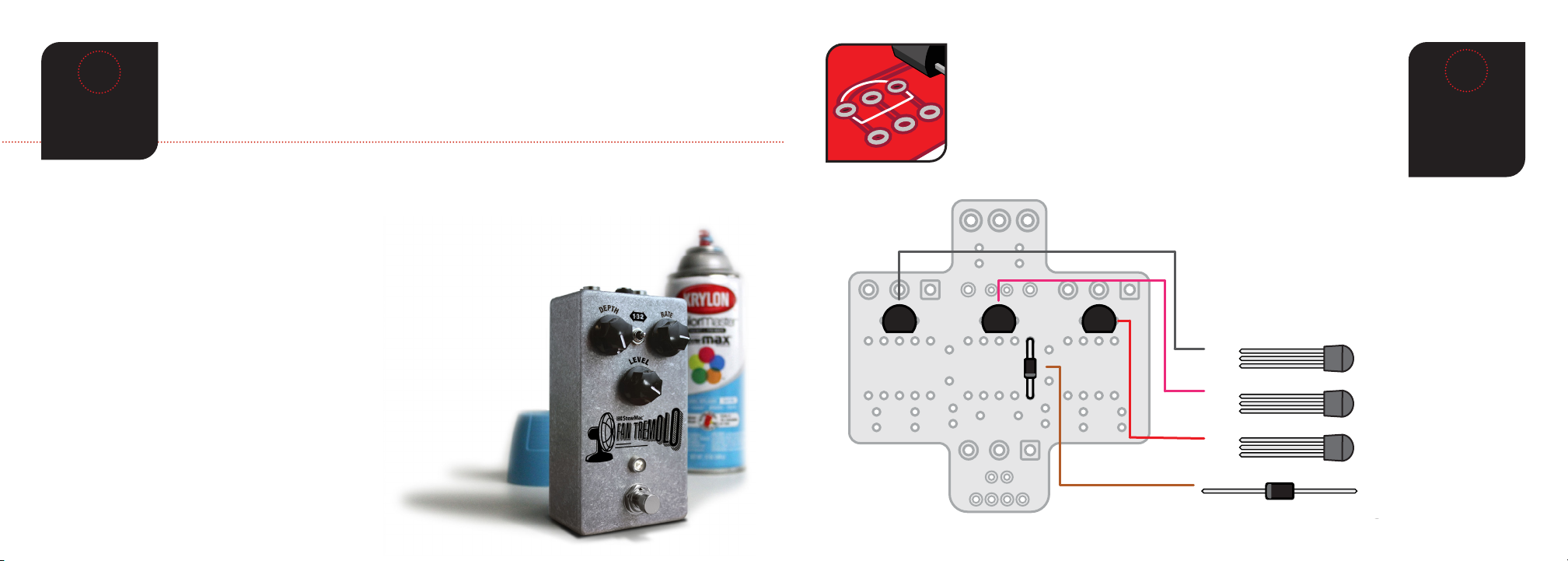
It’s time to install your parts! Before soldering the diode and
transistors to your Printed Circuit Board (PCB), make sure you thread
the legs through the correct side. The side of the PCB that has white
values and outlines of the components is the correct side. In some
cases, components must be inserted into the PCB in a specic
direction due to their polarity, so follow the graphics carefully.
INSTALL
1 DIODES
AND 3
TRANSISTORS
2
1N5817 rectifier diode (1)
#7522
1N4148 rectifier diode (2)
#7470
Linear voltage
regulator (1) #7508
1N5817 rectifier diode (1)
#7522
1N4148 rectifier diode (2)
#7470
Linear voltage
regulator (1) #7508
2N6027
Note the stripe around one end of the diode. This marks
the negative (minus) lead. On the PCB, the printed
outline of the diodes also shows this stripe. Install each
diode to match the direction shown. Similarly, the
transistors are directional, and must be installed in a
specic orientation. Match the at side of the
transistors to the outline printed on the PCB.
FKH09
PF
5102
CEN
2N5
089
2N6027 transistor (1)
#7515
2N
6027
C45
PF5102 transistor (1)
#7518
2N5089 transistor (1)
#7514
1N5817 rectifier diode (1)
#7522
Note the stripe around one end of the diode. This
marks the negative (minus) lead. On the PCB, the
printed outline of the diodes also shows this stripe.
Install the diode to match the direction shown.
Similarly, the transistors are directional, and must be
installed in a specic orientation. Match the at side
of the transistors to the outline printed on the PCB.
1. To minimize redoing steps,
make sure you have a solid idea of
the look and feel you’re going for.
2. Lightly sand housing with a 220
grit sandpaper and wipe clean any
debris.
3. Cover the holes from the
inside with masking tape.
4. On a large piece of cardboard,
elevate the housing top and
bottom on a couple of small
blocks of wood.
5. With long, slow strokes, spray
1 light coat of primer or primer/
paint on top and bottom. Allow
45 mins of drying time between
next two to three coats.
6. If you’re using primer followed
by paint method, paint 3 coats
with 45 mins between coats.
7. Now, add your Fan Tremolo
sticker and any other desired
decoration (paint pens, acrylic
paint, Sharpie etc.).
Allow drying time.
8. Add 3 coats of clear coat glaze
with 45 mins between coats.
Wait at least 2 hours
before adding parts.
You’re about to create a pedal from the ground up, so why not give your pedal a custom
paint job? Painting your pedal and adding the sticker provided in this kit (or custom
decals that you can create on your own) in advance is not only fun, but it’s much easier
than disassembling the pedal to paint it once you put it together.
PAINTING
YOUR PEDAL
HOUSING
1

Next, we’re going to add a bunch of resisitors to our PCB. Like in the previous step, you’ll
nd an outline of each resistor and its value printed in their proper location on the PCB.
Match resistors to the values on the PCB and solder in place.
Resistors are not polarized, so it doesn’t matter which lead goes in which eyelet.
INSTALL 13
RESISTORS
3
Red Red Black Brown Brown
Brown Red Black Red Brown
2.2K resistor (2) #7376
12K resistor (1) #7392
Yellow Purple Black Black Brown
470Ω resistor (2) #7355
Yellow Purple Black Brown Brown
4.7K resistor (1) #7359
Brown Black Black Black Brown
100Ω resistor (1) #7352
Resistors have a low prole, sitting closer to the board
than taller components, so installing these now will make
installing other parts easier later on.
Brown Black Black Yellow Brown
Red Red Black Red Brown
Red Purple Black Red Brown
Yellow Purple Black Red Brown
Red Red Black Orange Brown
1M resistor (1) #7367
22K resistor (1) #7379
27K resistor (1) #7398
47K resistor (2) #7369
220K resistor (1) #7381
101J
100V
100uF
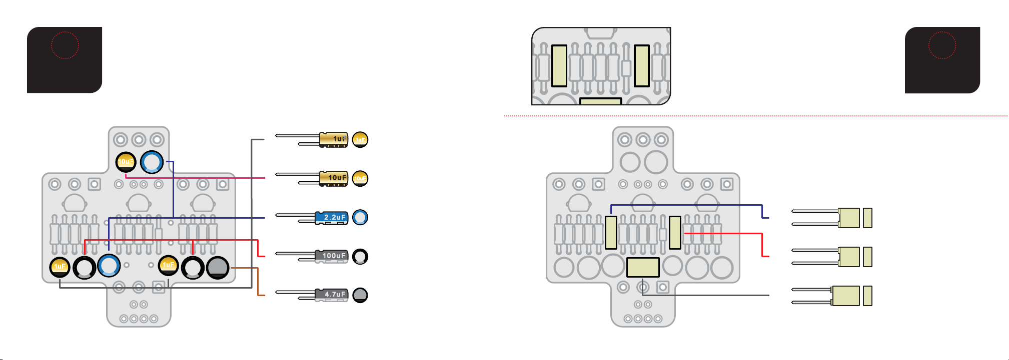
INSTALL11
CAPACITORS
4
The three types of capacitors shown below are polarized and have to be installed in
the correct orientation. Note the stripe running the length of each cap; this identies
the negative (minus) lead. On the circuit board, the circle for this cap’s location has a
round through hole on one side, and a square through hole on the other: insert the
capacitors with their stripe facing the round hole side. (On polarized caps of this type,
there’s a second way to identify the negative lead: it is the shorter of the two leads).
1uF
1uF
10uF
10µF capacitor (1)
#7338
100µF capacitor (2)
#7312
10uF
1µF capacitor (2)
#7337
1uF
100uF
4.7µF capacitor (1)
#7316
4.7uF
2.2µF capacitor (2)
#7315
2.2uF
1uF
10uF
.22J63
1J63
.1J63
220nF capacitor (1)
#7305
100nF capacitor (1)
#7304
.22J63
1µF capacitor (1)
#7308
1J63 .1J63
INSTALL3
CAPACITORS
5
The remaining capacitors below are not polarized.
However, best practice is to solder these caps in
place all facing the same direction.
.22J63
1J63
.1J63
220nF capacitor (1)
#7305
100nF capacitor (1)
#7304
.22J63
1µF capacitor (1)
#7308
1J63 .1J63

One 3-way toggle switch is included with the kit. Slide the switch lugs through the back
of the the three PCB holes at the top of the board and solder them.
You can use the pedal enclosure as a mount for the toggle switch while you solder the
PCB board to it. Just lay the enclosure face-up and drop the switch in its hole, you don’t
even need to fasten it with a nut from the back if you don’t want to.
INSTALL 1
SWITCH
6
.22J63
1J63
.1J63
.22J63
1J63
.1J63
The kit comes with 24" of lead wire.
Cut the wire into eight 2" sections and two 4" pieces.
Strip around 3/32" o both ends of all wires.
Solder the eight 2" leads on to main board in the
locations shown in the diagram.
INSTALL 8
LEAD WIRES
7
We nd it easiest to feed the free end of
each lead through the bottom of the PCB
and solder it on the top of the board.
TIP
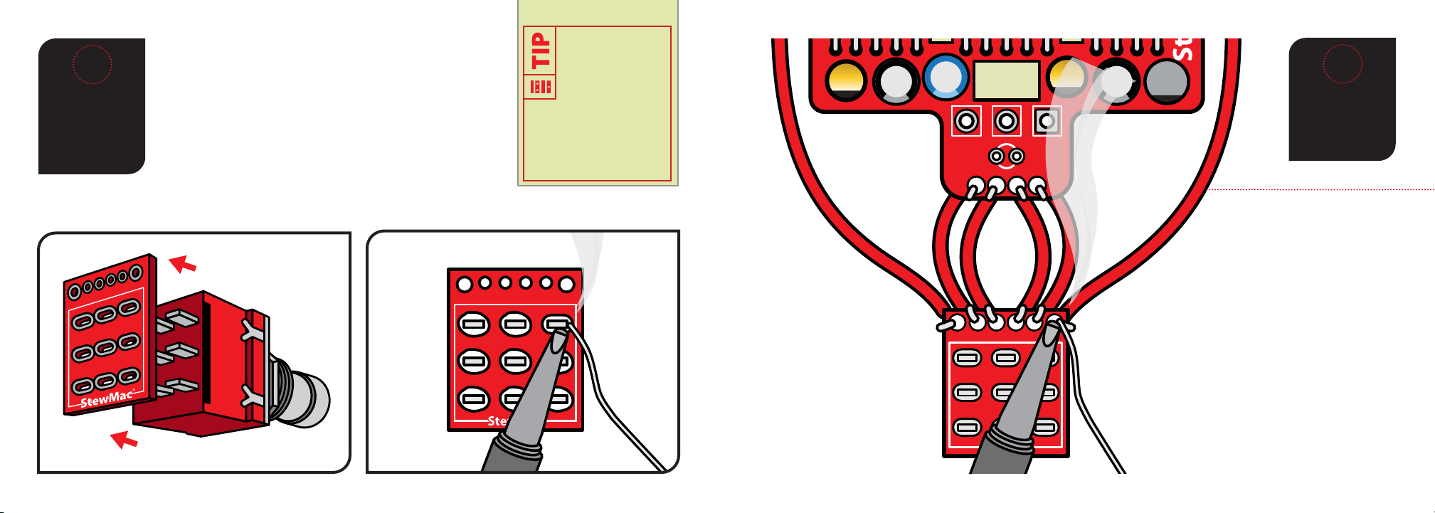
INSTALL
FOOTSWITCH
INTO
BREAKOUT
BOARD
8
Orient the breakout board with the text facing up,
reading left to right, and slide the lugs of the footswitch
up through the bottom of the board.
Solder each lug to the breakout board around it. If the
lugs of the footswitch don’t quite t in the breakout
board, use a pair of pliers to gently bend the lugs of the
footswitch until the breakout board will slide over the lugs.
IN GND SW OUT
IN G NDSW OUT
Just like the toggle
switch and the
PCB, you can use
the pedal enclosure
as a mount for the
footswitch while you
solder the breakout
board to it.
9
ATTACH 6
WIRES TO
BREAKOUT
BOARD
.22J63
1J63
.1J63
IN GND SW OUT
Solder the four wires from the bottom of the
main board to their corresponding holes in
the breakout board.
Solder the one free end of each 4" wire to the
last two holes on the breakout board.
LEVEL
(B100K)
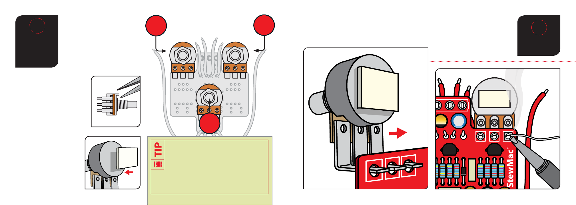
10
If any pot has an index pin
protruding from the case,
break it o before installation,
so the pot will mount ush
against the pedal case.
Needle nose pliers work well
for removing the pins.
The last components to go onto
the circuit board are the three
control pots. They install on the
back of the board. Each pot has
three connecting lugs. Note
orientation of each pot.
INSTALL
POTS AND
ATTACH
FOAM TAPE
TIME
Once you’ve removed any index pins and
added the foam tape to the back of each pot,
use the pedal enclosure as a mount for the
control pots while you solder the PCB to them.
Just lay the enclosure face-up and arrange the pots
in their holes, you don’t even need to fasten them
with a nut from the back if you don’t want to.
Use the adhesive foam tape
to insulate the back of the
pots from the soldered
leads of the other parts on
the circuit board. This is
especially important on the
“level” pot.
DEPTH
(B10K)
RATE
(B100K)
SOLDER
POTS TO PCB
11
Solder the pots in place, making sure the foam back stays on the back of the pot.
This insulates the solder joints on the PCB from shorting to the housing of the pot.
.22J63
1J63
.1J63
IN GND SW OUT

case
5mm LED mounting bezel (1) #7432
5mm white LED (1) #7422
case
The LED mounting bezel consists of two main parts: a
ring that the LED ts into, and a plastic plug that goes
over the LED from the back side to keep it in place.
Install the mounting bezel through the front of the
enclosure. From the inside, slip a lock washer and nut
on and tighten it up using a 3/8" socket. Insert the LED
into the bezel so the at side (the shorter lead) faces to
the right side of the case when looking from the back.
Feed the leads through the plastic plug, press the plug
down until it’s tight in the bezel. The LED will be held
in place when you solder the leads to the switches and
circuit board. For a more secure mount, you can run a
bead of clear silicone adhesive around the plastic plug.
12
INSTALL 1
LED
INDICATOR
LIGHT
Like some of the caps and diodes,
the LED is polarized and has to be
installed in a specic direction. The
negative lead of the diode has a at
edge and is shorter than the positive.
++
.22J63
1J63
.1J63
IN GND SW OUT
The circuit board is held in place by the
control pots, but the LED leads need to
pass through their eyelets in the PCB
before the pots will pass through the
enclosure. Pass the longer
positive lead through
the hole marked “A”
and the shorter negative lead through
the hole marked “K”. Once the pots are
secured to the enclosure, solder these
leads in place.Install their shafts through
the top of the case, and thread washers onto them on
the outside. Using a 10mm wrench, install the mounting
nuts so they are good and snug, but take care not to
overtighten.
Install the footswitch through the top of the case and
thread a washer onto it from the outside. Use a 14mm
wrench to tighten it up. The footswitch is the eect bypass
switch that turns the pedal on.
Do not connect any of the lead wires at this point. Once all
of the pots are tightened down, twist the pot shafts all the
way counter-clockwise and install the knobs pointing at “7
o’clock” indicating a the “zero” position.
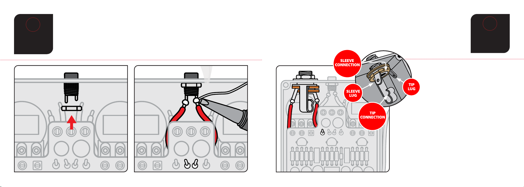
Insert the DC jack into the top of the housing making sure the longer of the two lugs
is on the left. Using a 14mm wrench and 14mm nut, secure jack into housing.
Solder the inside left wire to the longer lug of the DC jack.
Solder the inside right wire to the shorter lug of the DC jack.
14
INSTALL
DC JACK
INSTALL
THE INPUT
JACK
15
Insert the input jack into the left side of the housing with the tip connection facing
down, as shown in the diagram. Add the washer and thread the nut on to the shaft
enough so that the pot can rotate freely. You may need to rotate the jack to provide
easier access to setting the solder joints.
Solder the left most wire at the top of the
board to the input jack lug that corresponds
with the sleeve connection. The sleeve
connection lug should be the one
closest to the DC jack.
Solder the 4" wire on the left side of the
footswitch board to the lug of the input jack that
corresponds with the tip connection. The tip
connection lug should be the one closest to the
outside wall of the enclosure.
Once the solder has cooled, orient the jack as
shown in the diagram, make sure none of the
connections on the jack are shorting to any other
components, and tighten the nut on the jack.
Shield lug Tip connection
Tip lugShield connection

16
INSTALL
THE OUTPUT
JACK
Insert the output jack into the right side of the housing with the tip connection facing
up, as shown in the diagram. Add the washer and thread the nut on to the shaft
enough so that the pot can rotate freely. You may need to rotate the jack to provide
easier access to setting the solder joints.
Solder the right most wire at the top
of the board to the output jack lug that
corresponds with the sleeve connection.
The sleeve connection lug should be the
one closest to the DC jack.
Solder the 4" wire on the right side of the
breakout board to the lug of the output jack that
corresponds with the tip connection. The tip
connection lug should be the one closest to the
outside wall of the enclosure.
Once the solder has cooled, orient the jack as
shown in the diagram, make sure none of the
connections on the jack are shorting to any other
components, and tighten the nut on the jack.
Shield lug Tip connection
Tip lugShield connection
COMPLETED
VIEW
17
.22 J 63
1J63
.1J63
IN GND SW OUT
With the output jack secured, this is what your pedal
should look like.
Congrats on a job well done.
Now, simply attach the back of the pedal, pop on the
knobs, plug this thing in and bend some tone!

POWER: Use a standard 9 volt DC power
supply with a 2.1mm negative-center barrel (not
included). We always recommend pedal-specic,
transformer-isolated wall-wart power supplies or
supplies with separate isolated outputs. Pedals
will make extra noise if there is ripple or unclean
power. Switching-type power supplies, daisy
chains, and non-pedal specic power supplies
do not lter dirty power as well and let through
unwanted noise. Do not run at higher voltages!
Current draw is 25 mA.
DEPTH: This control could also be labeled Mix or
Intensity. A low setting will have a very low eect
on the signal and the more you turn the knob the
more intense or“deep”the tremolo eect will be.
HERE’S HOW THE CONTROLS WORK INPUT
OUTPUT 9V DC
BYPASS
D
E
P
T
H
R
A
T
E
132
L
E
V
E
L
NOTES
MODE: This 3-way toggle switch selects which
type of oscillation you would like. All the way left
is a subtle, early 60’s style oscillation. All the way
right is a slightly faster and heavier“opto-isolator”
style tremolo, more like the eect found in amps
in the late 60’s and 70’s. The middle position is a
very modern, almost digital style oscillation that
can easily achieve ring-mod style tremolo.
RATE: This adjusts the speed of the oscillations.
LEVEL: There is a slight boost in the circuit to
help compensate for the perceived volume drop
associated with tremolo eects. A lower setting
means a lower output, and a higher setting
results in, you guessed it, a higher output. We’re
guilty of sometimes turning the depth very low
and the level up higher and using this pedal as a
clean boost with a touch of shimmer.

TL072 PT2399
IN GND SW OUT
NOTES
THE STEWMAC
FAN TREMOLO

TECHNICAL SUPPORT:
If you have any questions before,
during, or after this project, please do
not hesitate to reach out to our Tech
Support Team. They are available by
21 N. Shafer St., Athens, OH 45701
stewmac.com
©2020 StewMac. All rights reserved. • #2351 Updated February 2020
Table of contents
Other StewMac Music Pedal manuals

StewMac
StewMac EC EXPANDER PEDAL KIT Manual

StewMac
StewMac TAPE OP DELAY Manual

StewMac
StewMac NYC BIG MUFF PI User manual

StewMac
StewMac LIGHTCYCLE PHASOR II Manual

StewMac
StewMac TWO KINGS BOOST DOUBLE-POWERED ROYAL TONE Manual

StewMac
StewMac Monarch User manual

StewMac
StewMac Disaster Transport User manual

StewMac
StewMac MXR PHASE 90 User manual

StewMac
StewMac SUN FUZZ Manual

StewMac
StewMac SWELL DRIVE Manual


