StewMac SWELL DRIVE Manual

SWELL DRIVE
PEDAL KIT
INSTRUCTION GUIDE
©2020 StewMac • All rights reserved • i-2355 Updated September 2020
stewmac.com
BASED ON THE
RARE AND ICONIC
BOSS SLOW GEAR,
an eect that gives the sound of a volume control being
rolled up after a note or chord is hit. A single obsolete
component prevents this pedal from being mass produced
but we have found a stash that enables us to oer these
kits. When they’re gone, they’re gone!
POWER
This pedal requires a standard 9V DC center-negative
power supply (not included) and consumes less than
100mA. There’s no battery option.
TECHNICAL SUPPORT
If you have any questions before, during, or after this
project, please do not hesitate to reach out to our
Tech Support Team. They are available by email at
22nJ
47nJ
22nJ
47nJ
33nJ
TL072
1uF 10u F
10uF
1uF 1uF 1uF 1uF
08 EDT
10uF
1uF
IN GND SW OUT

2
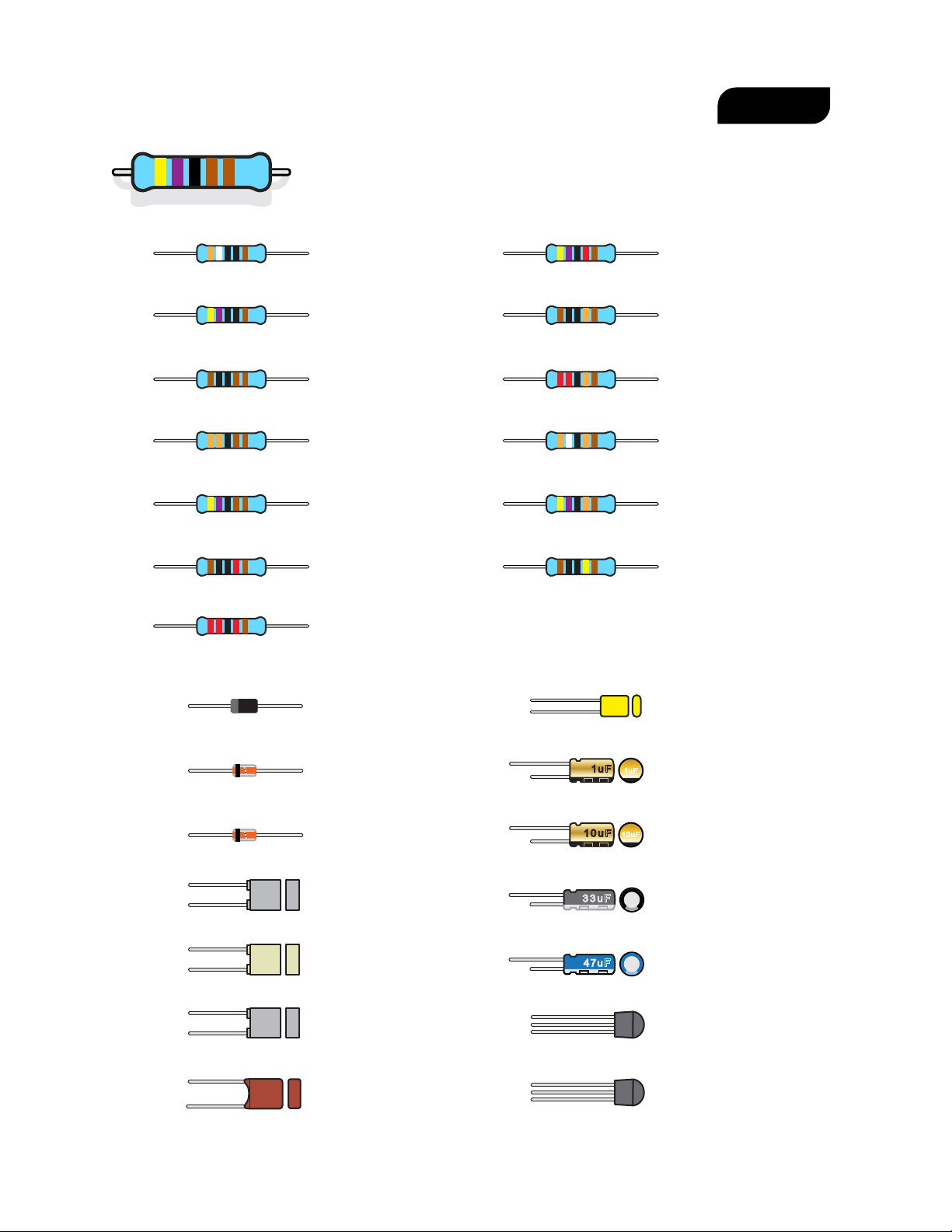
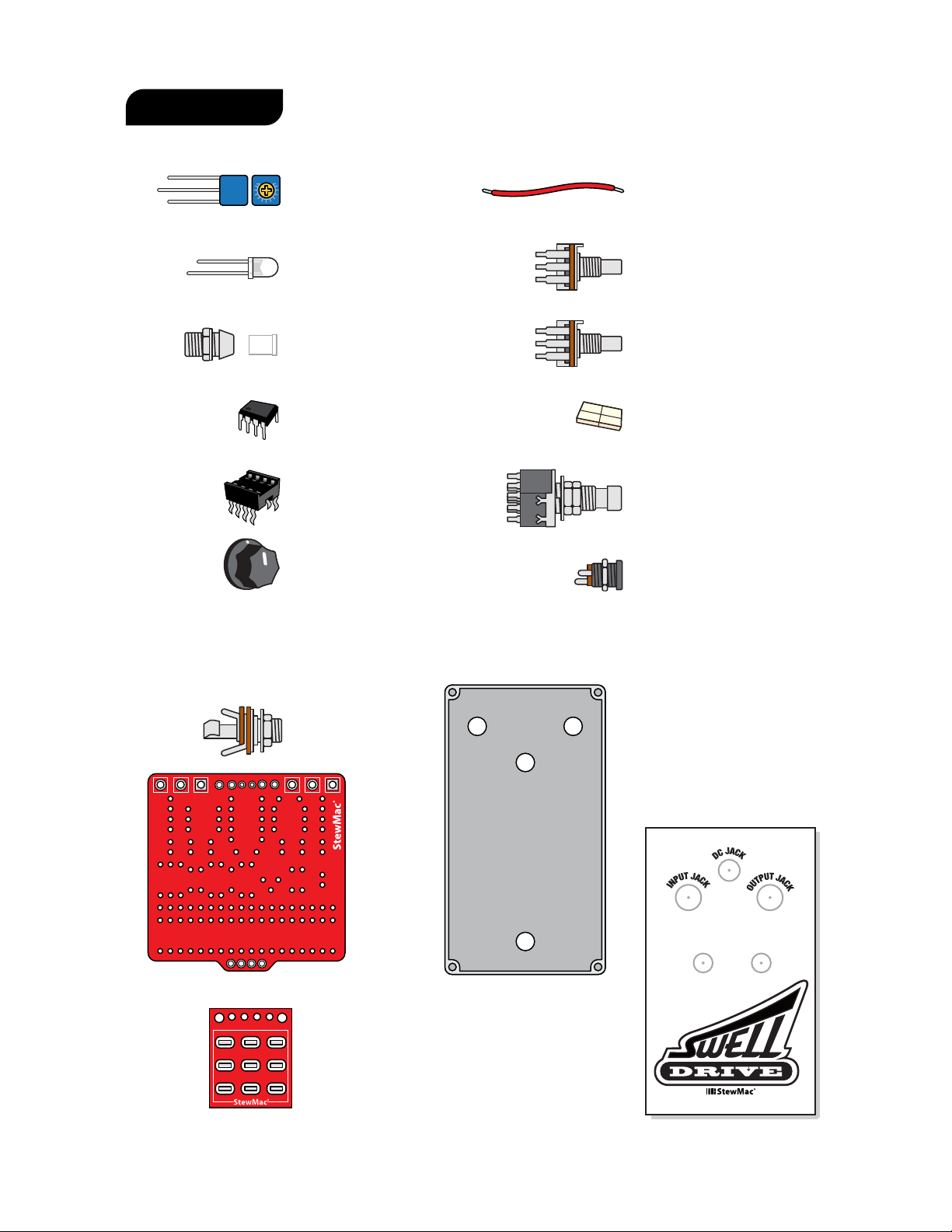
PARTS LIST
TOOLS AND SUPPLIES REQUIRED
TOOLS AND SUPPLIES HELPFUL
Soldering Iron #0502
Solder Wick #0504
Solder #0505
Wire Cutter #1607
Long-nose pliers #1610
Fine-gauge Wire
Stripper #1606
Guitar Tech Screwdriver
and Wrench Set #3693
Not pictured:
Clear silicone adhesive and spray nish
PC Board Holder #0500
Magnifying glass or
OptiVISOR #1685
Soldering Aids #0521
Multimeter #3607
3M Gold Fre-Cut
Sandpaper (220-grit) #5097
3
390Ω resistor (1) #7349
Orange White Black Black Brown
470Ω resistor (1) #7355
Yellow Violet Black Black Brown
1K resistor (3) #7357
Brown Black Black Brown Brown
3.3K resistor (1) #7377
Orange Orange Black Brown Brown
4.7K resistor (3) #7359
Yellow Violet Black Brown Brown
10K resistor (3) #7362
Brown Black Black Red Brown
47K resistor (1) #7369
Yellow Violet Black Red Brown
100K resistor (3) #7365
Brown Black Black Orange Brown
220K resistor (1) #7381
Red Red Black Orange Brown
390K resistor (1) #7419
Orange White Black Orange Brown
470K resistor (2) #7382
Yellow Violet Black Orange Brown
1M resistor (4) #7367
Brown Black Black Yellow Brown
22K resistor (3) #7379
Red Red Black Red Brown
33µF capacitor (1) #7477
33uF
33nF capacitor (1) #7475
33nJ
BC549 transistor (5) #7510
BC549
C
-J23
2SK30A transistor (1) #7517
K30A
GR7L
22nF capacitor (2) #7317
22nJ
47nF capacitor (2) #7307
47nJ
1nF capacitor (1) #7302
102J
1N914 rectier diode (3) #7521
5V6 rectier diode (1) #7520
1N5817 rectier diode (1) #7522
10µF capacitor (3) #7338
10uF
1µF capacitor (6) #7337
1uF
47µF capacitor (1) #7478
47uF
1uF
10uF
470nF capacitor (1) #7336
474J
100V
PARTS LIST
Resistor values are indicated by color bands, read from left to right.
The rst color in the code is usually the one painted closer to a lead wire.
See more about resistor color codes on page 5.
4
5mm white LED (1)
#7422
10K trim pot (1)
#7570
3PDT latching footswitch (1)
#1611
B25K linear taper attack pot (1)
#7461
B100K linear taper sensitivity pot (1)
#7453
24" of lead wire (1)
#5960
Adhesive foam tape square (4)
#7560
5mm LED mounting bezel (1)
#7432
TL071 low noise distortion op-amp (1)
#7509
Integrated circuit socket (1)
#7484
Control knob (2)
#7501
08 EDT
2.1mm DC power jack (1)
#7468
PARTS LIST CONT
A
T
T
A
C
K
S
E
N
S
I
T
I
V
I
T
Y
1/4" mono jack (2)
#4652
Printed circuit board (1)
Sticker sheet (1)
Breakout board (1)
IN GND SW OUT
Pre-drilled enclosure top (1)
Pre-drilled enclosure bottom - not pictured (1)
Screws - not pictured (4)

5
the one painted closest to a lead wire. When a gold
or silver band is present, it’s always one of the last
colors in the code. If you’re having trouble reading
the color bands, try using a multimeter to read the
resistor’s value. Just set your multimeter to ohms and
connect its test leads to each side of the resistor.
A number of dierent components are used to make
an eects pedal. Here is a look at the components
used in this kit:
RESISTORS
A resistor does exactly what it says—it resists the
ow of current. The designated value of the resistor
corresponds to how much resistance there is on the
ow of electrons.
A resistor’s value—the amount of resistance it
creates—is rated in ohms (). Larger ohm values
mean more resistance. For example, a 100
resistor creates ten times as much resistance
as a 10 resistor.
Resistor values are indicated by color bands, read
from left to right. The rst color in the code is usually
UNDERSTANDING ELECTRONIC
COMPONENTS
Band 1 Band 2 Band 3 Band 4 Band 5
1st Digit 2nd Digit 3rd Digit Multiplier Tolerance
6 8 x100
+/- 1%
68K +/- 1%
K=1,000
Blue
Read this band rst (closest to an end)
Gray Black Red Brown
BLACK 0 0 0 1
BROWN 1 1 1 10 +/- 1%
RED 2 2 2 100 +/- 2%
ORANGE 3 3 3 1,000
YELLOW 4 4 4 10,000
GREEN 5 5 5 100,000 +/- .5%
BLUE 6 6 6 1,000,000 +/- .25%
VIOLET 7 7 7 10M +/- .1%
GRAY 8 8 8 .01 SILVER
WHITE 9 9 9 .1 GOLD
0
SOLDERING MORE HELPFUL
SOLDERING TIPS
AND TRICKS
•Keep your soldering tip
clean by wiping it often
on a damp sponge.
• Also keep it tinned by
occasionally melting
a little solder onto it.
•Don’t blow on the
hot solder or touch
anything until the joint
has cooled completely.
A good solder joint
is shiny—a sign that
it was left to cool
undisturbed.
• Plan so each joint is
only soldered once.
Resoldered joints are
messy and more likely
to fail.
The solder joints you’ll make on the printed circuit
board are very small, and too much heat can damage
the board. The idea is to make joints quickly, without
scorching the eyelets.
1. Hold components in place for soldering by
threading the leads through the board and bending
them apart on the reverse side. You will be making
your solder joints on the reverse side of the board.
2. Melt a small amount of
solder onto the tip of
the iron (“tinning” the iron).
3. Insert the tip into the eyelet and let it heat for 4-5
seconds before touching it with solder. This heats the
contact enough for the solder to ow nicely without
damage. Feed the solder to the eyelet, not the iron,
and you don’t need much solder, just enough to ll
the eyelet. Keep the iron on the connection for a
second longer; this pause gives time for all of the ux
to cook out of the joint. After the joint has cooled,
trim away the excess lead wire.
6
called nanofarads (nF), or trillionths of a farad, called
picofarads (pF). .001μF = 1nF = 1,000pF.
Resistors and capacitors may also be referred to with
shorthand notation on the printed circuit board
when there is a decimal in the value. For example,
the place on the printed circuit board for the 4.7K
resistor will read 4K7 and the spot for a 2.2nF
capacitor will read 2n2. This is done to save space on
the board and make the labels as clear as possible.
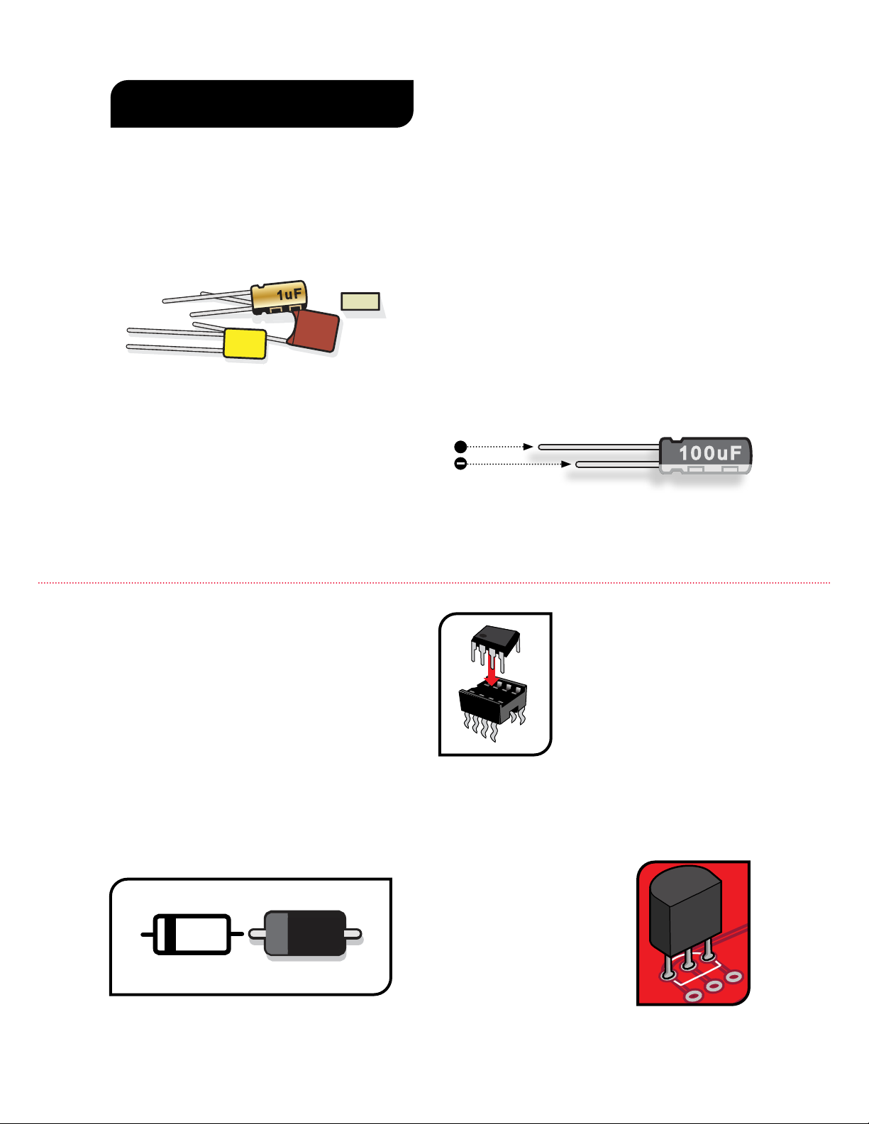
Some capacitors have polarity and some don’t.
It’s extremely important to install polarized caps
correctly in a circuit. The negative lead will often
be indicated by a stripe on the negative lead’s side
(often with arrows) and will be shorter than the
positive lead. The positive lead of an electrolytic cap
will be longer and won’t have the stripe on that side.
Installing capacitors with the polarity backwards will
make the circuit malfunction and quickly destroy the
capacitor—even causing it to explode.
CAPACITORS
The two main uses of capacitors are to store
electricity and to block the ow of DC current.
Capacitor values are typically printed on the
component. The key values with caps are their
voltage and capacitance.
The voltage spec for a cap refers to how much DC
voltage it can handle at any given time. If this rating
is exceeded, the capacitor will fail.
Capacitance, measured in farads, refers to how
much electricity a capacitor can hold. One farad
(1F) would be much too large for use in a pedal.
Caps for pedals are rated between millionths of a
farad, called microfarads (F), billionths of a farad,
101J
100V
102J
1u F
.1J63
++
UNDERSTANDING ELECTRONIC
COMPONENTS
INTEGRATED CIRCUITS
Integrated circuits are tiny and
complex—complete circuits
containing many components.
Their connecting leads plug
into a socket, making them
easy to remove and replace for
experimenting with dierent
sounds. Various types of integrated circuits include
audio processors, voltage regulators, and operational
ampliers (op-amps), which multiply the input signal.
2n2J630
TL072
PT2399
PT2399
PT2399
PT2399
echo audio
processor (1) #7490
TL072CP TL072CP
low noise
op-amp (1) #7444
DIODES
Diodes are used where you want electricity to ow
in only one direction, such as power rectication,
and also to limit how much current can ow, to
create “clipping” distortion.
Diodes are also polarized, so they need to be
installed in the correct orientation. The stripe
around one end marks the negative (–) lead of the
diode. On the printed circuit board, the printed
outline of the diodes also shows this stripe. Install
each diode so that its stripe matches the direction
shown on the printed circuit board. TRANSISTORS
Transistors are used to amplify
electrical signals. They have
a at side and a round side.
The location on the printed
circuit board also has a at side
and a round side. Match the
orientation of the component
to this outline.
2N5089

7
POTENTIOMETERS
A potentiometer, or pot, is a variable
resistor. This means as the knob
shaft is rotated, the DC resistance
will change. There are three lugs
or soldering terminals on a
conventional potentiometer.
The outside two are the ends
of the resistive strip, and the
center lug is connected to
the wiper. The wiper allows you
to vary the DC resistance relative
to its position along the resistive
strip, or relative to the
outer two lugs.
Potentiometers come in
two varieties, linear taper
and audio taper. The linear
taper pot’s taper works at a 1:1
ratio. Audio taper has a special
logarithmic ratio.
Audio taper is used because our ears don’t hear
changes in volume in a linear fashion as you might
expect. As the volume increases, a greater change
in signal or sound pressure is required to perceive a
smooth transition.
LEDs
LED stands for Light Emitting Diode,
and functionally LEDs are very similar to
regular diodes. LEDs are most often used
as indicator lights in pedals. They are
polarized just like diodes and electrolytic
capacitors and must be installed in the
correct orientation to work. The positive
(anode) lead of the LED will be longer and
the anode side of the LED housing will be
round. The negative (cathode) lead of the
LED will be shorter and the cathode side
of the LED housing will be at. LEDs are
mounted inside of a bezel, which protects
the LED and insulates the leads from
shorting against the enclosure or any
internal components.
UNDERSTANDING ELECTRONIC
COMPONENTS
PAINTING
YOUR PEDAL
ENCLOSURE
1
1. To minimize redoing steps,
make sure you have a solid idea of
the look and feel you’re going for.
2. Lightly sand the outside of
the enclosure with 220-grit
sandpaper and wipe clean any
debris.
3. Cover the holes from the
inside with masking tape.
4. On a piece of cardboard, place
the enclosure and bottom cover
on scraps of wood to lift them o
the cardboard when spraying.
5. With long, even strokes, spray
a light coat of primer or paint.
Allow 45 minutes of drying time
before the next coat.
6. If you’re using primer-
followed-by-paint method, paint
three coats with 45 minutes
between coats.
7. Now, add your included
stickers and any other desired
decoration (paint pens, acrylic
paint, Sharpie, etc.).
Allow drying time.
8. Add three coats of clear-coat
glaze with 45 minutes between
coats. Wait at least two hours
before adding parts.
You’re creating a pedal from the ground up, so add your own custom paint job too!
Painting your pedal and adding the stickers provided in this kit (or custom decals
that you can create on your own) in advance is not only fun, but it’s much easier than
disassembling the pedal to paint it once you have put it together.
8
5V6 diode (1) #7520
1N5817 rectier diode (1) #7522
BC549 transistor (5) #7510
BC549
C
-J23
K30A
GR7L
1N914 diode (3) #7521
2SK30A transistor (1) #7517
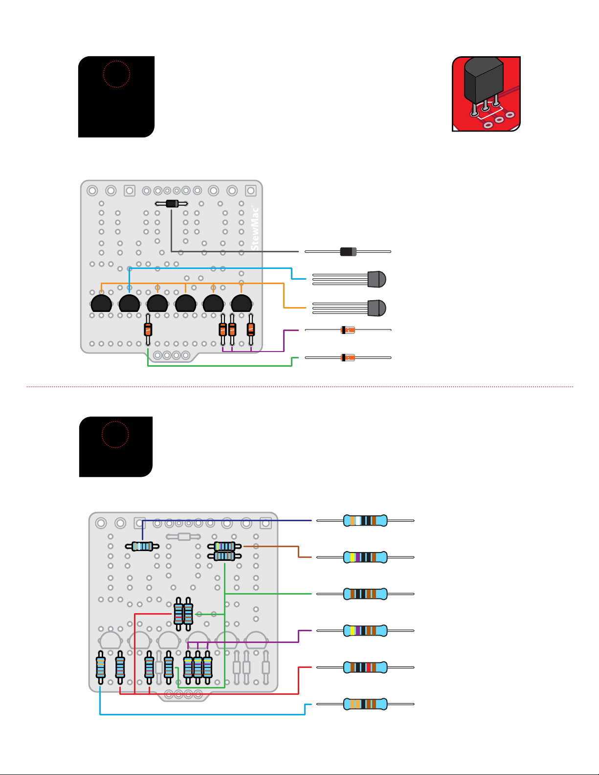
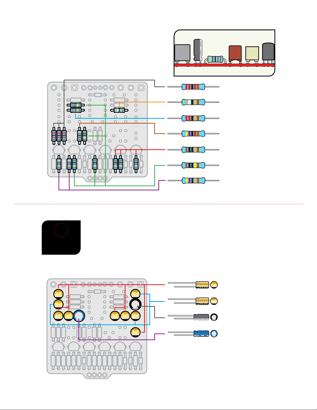
INSTALL
5 DIODES
AND 6
TRANSISTORS
2
INSTALL 27
RESISTORS
3
390Ω resistor (1) #7349
Orange White Black Black Brown
470Ω resistor (1) #7355
Yellow Violet Black Black Brown
1K resistor (3) #7357
Brown Black Black Brown Brown
3.3K resistor (1) #7377
Orange Orange Black Brown Brown
10K resistor (3) #7362
Brown Black Black Red Brown
4.7K resistor (3) #7359
Yellow Violet Black Brown Brown
2N5089
It’s time to install your parts! Before soldering the diodes and
transistors to your printed circuit board, make sure you thread the
leads through the correct side. The side of the printed circuit board
that has white values and outlines of the components is the correct
side. In some cases, components must be inserted into the printed
circuit board in a specic direction due to their polarity, so follow the
graphics carefully.
Note the stripe around one end of each diode. This marks the
negative (–) lead. On the printed circuit board, the printed
outline of the diode also shows this stripe. Install the diode to
match the direction shown, and solder in place. Similarly, the
transistors are directional, and must be installed in a specic
orientation. Match the at side of the transistors to the outline
printed on the printed circuit board.
Next, we’re going to add a bunch of resistors to our printed circuit board. As in the
previous step, you’ll nd an outline of each resistor and its value printed in their proper
location on the printed circuit board. Match resistors to the values on the printed circuit
board and solder in place.
Resistors are not polarized, so it doesn’t matter which lead goes in which eyelet.
9
10K
10K
10K
10K
10K
10K
10K
470K
100K
1M
20K
22K
22K
22K
1K
47K
47K
220K
220K
4k7
1K resistor (1) #7357
BrownB lack BlackB rown Brown
BrownB lack BlackO range Brown
100K resistor (1) #7365
Yellow Purple BlackR ed Brown
47K resistor (3) #7369
RedR ed BlackO range Brown
220K resistor (2) #7381
BrownB lack BlackY ellowB rown
1M resistor (1) #7367
Yellow Purple BlackO range Brown
470K resistor (2) #7382
RedR ed BlackR ed Brown
22K resistor (3) #7379
RedB lack BlackR ed Brown
20K resistor (1) #7397
Yellow Purple BlackB rown Brown
4.7K resistor (1) #7359
47K resistor (1) #7369
Yellow Violet Black Red Brown
220K resistor (1) #7381
Red Red Black Orange Brown
390K resistor (1) #7419
Orange White Black Orange Brown
470K resistor (2) #7382
Yellow Violet Black Orange Brown
22K resistor (3) #7379
Red Red Black Red Brown
100K resistor (3) #7365
Brown Black Black Orange Brown
1M resistor (4) #7367
Brown Black Black Yellow Brown
INSTALL 11
CAPACITORS
4
1uF 10uF
10uF
1uF 1uF 1uF 1uF 10uF
1uF
1uF
10uF
10µF capacitor (3)
#7338
33µF capacitor (1)
#7477
10uF
33uF
47µF capacitor (1)
#7478
47uF
1µF capacitor (6)
#7337
1uF
10uF
Resistors have a low prole, sitting closer to the board
than taller components, so installing these now will make
installing other parts easier later on.
The three types of capacitors shown below are polarized and must be installed in the
correct orientation. Note the stripe running the length of each cap; this identies the
negative (–) lead (the negative lead is also shorter).
On the printed circuit board, each capacitor has a square-shaped eyelet marked positive (+).
The negative lead’s eyelet is round.
10
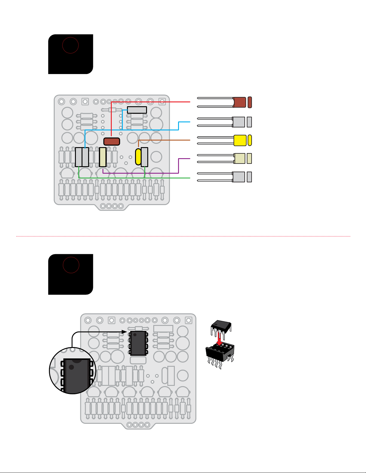
INSTALL 7
CAPACITORS
5
1u
+
1u
+
+
100u
+
10u
+
100u
+
100u
1u
+
1u
+
1u
+
+
10u
100pF
22n
22n
22n22n
22n
22n
220n
2n2
1n
100n
100n
100n
100n
100n
100n
.0022µF capacitor (1) #7324
.22µF capacitor (1) #7305
.1µF capacitor (6) #7304
100pF capacitor (1) #7326
101J
100V
.001µF capacitor (1) #7302
102J
2n2J630
.022µF capacitor (6) #7317
.1J63
.22J63
1µF capacitors (5) #7314
1uF
10µF capacitor (2) #7338
100µF capacitor (3)
#7312
10uF
100uF
10K
1M
470K
100K
22K
1K
47K
220K
10K
10K
10K
10K
10K
10K
10K
470K
22K
47K
47K
220K
22K
4K7
10K
1M
470K
100K
22K
1K
47K
220K
10K
10K
10K
10K
10K
10K
10K
470K
22K
47K
47K
220K
22K
4K7
22nJ
47nJ
22nJ
47nJ
33nJ
10uF
474J
100v
33nJ
33nF capacitor (1)
#7475
22nF capacitor (2)
#7317
470nF capacitor (1)
#7336
22nJ
MMK
BH8
50-
47nJ
47nF capacitor (2)
#7307
MMK
BHN
50-
102J
1nF capacitor (1)
#7302
TL071
INSTALL THE
OP-AMP
6
2n2J630
TL072
TL071
PT2399
PT2399
PT2399
echo audio
processor (1) #7490
TL071 low noise distortion op-amp (1)
#7509
Integrated circuit socket (1)
#7484
The remaining capacitors below are not polarized. However, best practice is to solder
these caps in place all facing the same direction when possible.
On the printed circuit board, note the marking for the integrated circuit socket: there is
a solid rectangle printed at one end. The socket itself has a notch at one end. Solder the
socket in place, with the notched end toward the rectangle on the board. Plug in the op-
amp, with the small dot on the op-amp oriented toward the notched end of the socket.
2n2J630
TL072
TL071
PT2399
PT2399
PT2399
echo audio
processor (1) #7490
TL071 low noise distortion op-amp (1)
#7509
Integrated circuit socket (1)
#7484
11
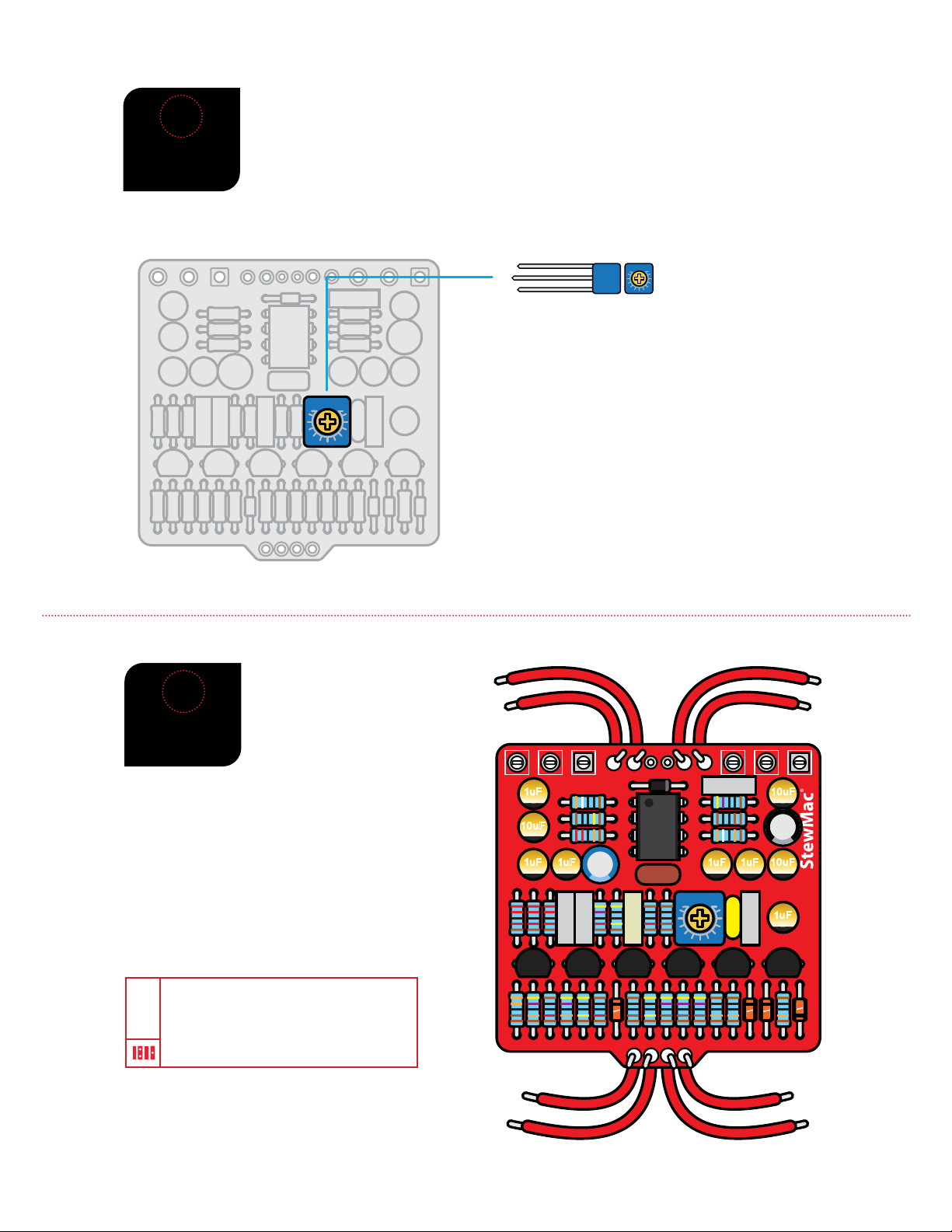
INSTALL THE
TRIM POT
7
Install the trim pot with the text facing the top of the board, as shown in the diagram.
This is a very small potentiometer that ne-tunes the pedal’s eect on the signal,
especially the attack. Use a screwdriver to set the trim pot to the midpoint of its range.
Near this midpoint is where we get the best results, but feel free to experiment with
dierent settings.
08 EDT
10uF
10K trim pot (1)
#7570
08 EDT
22nJ
47nJ
22nJ
47nJ
33nJ
TL071
1uF 10 uF
10 uF
1uF 1uF 1uF 1uF
08 E DT
10 uF
1uF
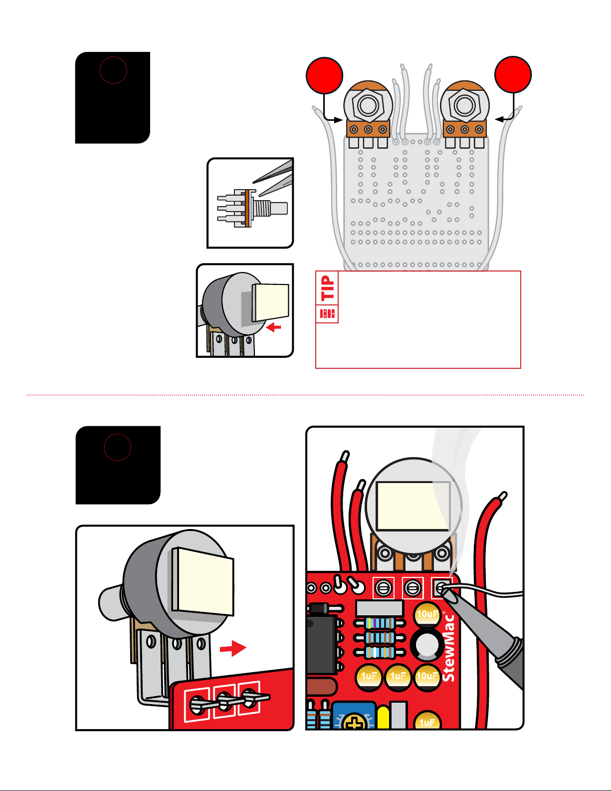
INSTALL 8
LEAD WIRES
8
The kit comes with 24" of lead wire.
Cut the wire into eight 2" sections and two 4" pieces.
Strip around 3/32" o both ends of all wires.
Solder the eight 2" leads onto the printed circuit
board in the locations shown in the diagram.
We nd it easiest to feed each lead
through the bottom of the printed
circuit board and solder it on the top
of the board.
TIP

12
10
ATTAC H 6
WIRES TO
BREAKOUT
BOARD
22nJ
47nJ
22nJ
47nJ
33nJ
TL072
1uF 10uF
10uF
1uF 1uF 1uF 1uF
08 EDT
10uF
1uF
IN GND SW OUT
Solder the four wires from
the bottom of the printed
circuit board to eyelets
in the breakout board as
shown.
Solder one end of each 4"
wire to the last two eyelets
on the breakout board.
INSTALL
FOOTSWITCH
INTO
BREAKOUT
BOARD
9
Orient the breakout board with the text facing
up, reading left to right. Slide the lugs of the
footswitch up through the bottom of the board.
If the lugs of the footswitch don’t quite t in the
breakout board, use a pair of pliers to gently
bend the lugs of the footswitch until the breakout
board slides over the lugs. Solder each lug to the
corresponding breakout board eyelet.
IN GND SW OUT
IN G NDSW OUT
You can use the pedal
enclosure as a mount for
the footswitch while you
solder the breakout board
to it. Just lay the enclosure face-
up and drop the switch in its
hole. No need to fasten it with
a nut from the back if you don’t
want to.
13
TIME
SENSITIVITY
(A100K)
ATTAC K
(B25K)
11
If either pot has an index pin
protruding from the case,
break it o before installation,
so the pot will mount ush
against the pedal case. Long-
nose pliers work well for
removing pins.
The last components to go onto
the printed circuit board are the
sensitivity and attack pots. They
install on the back of the board.
Each pot has three connecting
lugs. Note the orientation of
each pot.
INSTALL 2
POTS AND
ATTAC H
FOAM TAPE
Use a piece of the adhesive
foam tape to insulate the
back of the pots from the
soldered leads of the other
parts on the printed circuit
board.
Once you’ve removed any index pins and added
the foam tape to the back of each pot, use the
pedal enclosure as a mount for the control pots
while you solder the printed circuit board to
them. Just lay the enclosure face-up and arrange the
pots in their holes. No need to fasten them with a nut
from the back if you don’t want to.
SOLDER POTS
TO PRINTED
CIRCUIT BOARD
12
Solder the pots in place,
making sure the foam back
stays on the back of the pot.
This insulates the solder joints
on the printed circuit board
from shorting to the housing
of the pot.
22nJ
47nJ
22nJ
47nJ
33nJ
TL071
1uF 10uF
10uF
1uF 1uF 1uF 1uF
08 EDT
10uF
1uF
IN GND SW OUT
14
22nJ
47nJ
22nJ
47nJ
33nJ
TL071
1uF 10uF
10uF
1uF 1uF 1uF 1uF
08 EDT
10uF
1uF
IN GND SW OUT
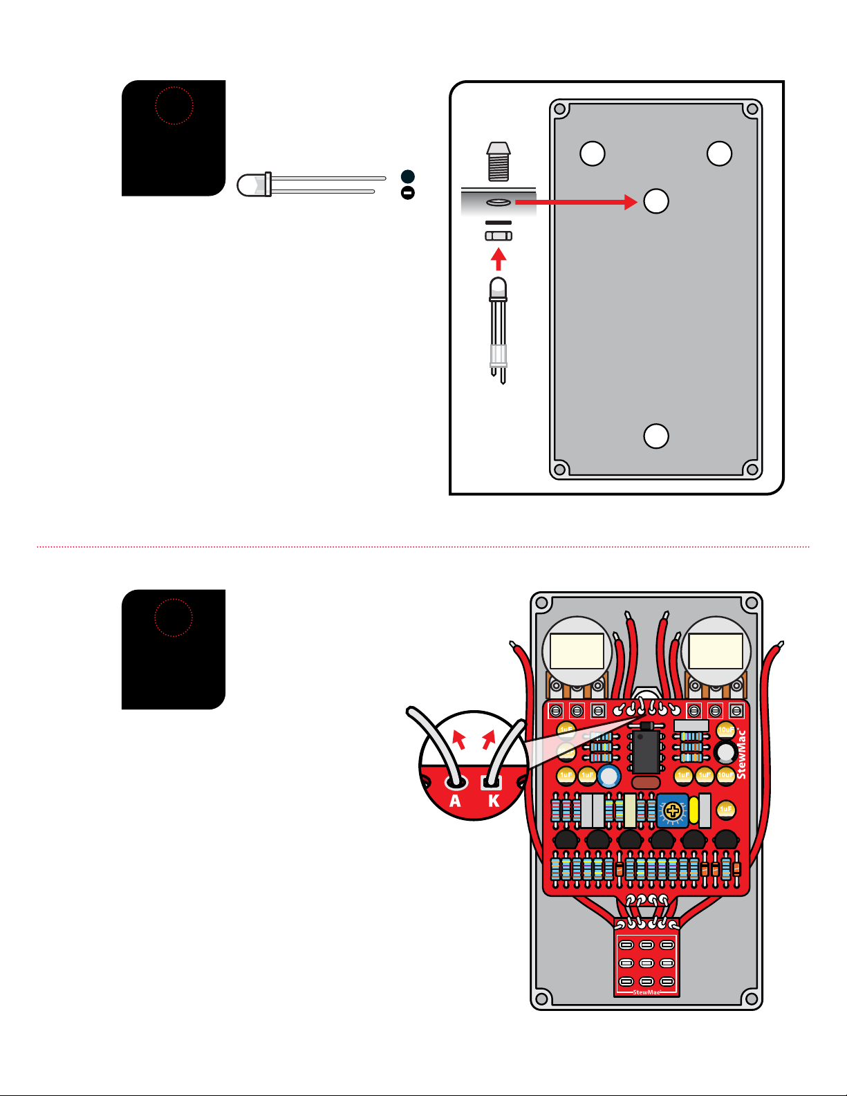
5mm LED mounting bezel (1) #7432
5mm white LED (1) #7422
case
The LED mounting bezel consists of two main parts:
A ring that the LED ts into, and a plastic plug that goes
over the LED from the back side to keep it in place.
Install the LED mounting bezel using its lock washer
and 3/8” nut. Insert the LED into the bezel with the
at side (shorter lead) facing right when seen from
inside as shown. Feed the leads through the plastic
plug, and press the plug into the bezel. The LED will
be held in place when you solder the leads in the next
step. For a more secure mount, run a bead of clear
silicone adhesive around the plug.
13
INSTALL
LED
INDICATOR
LIGHT
Like some of the caps and diodes,
the LED is polarized and has to be
installed in a specic direction. The
negative lead of the diode has a at
edge and is shorter than the positive.
++
The printed circuit board is held in
place by the control pots, but the
LED leads need to pass through their
eyelets in the printed circuit board
before the pots will pass through the
enclosure.
Pass the longer positive
lead of the LED through the eyelet marked“A”
and the shorter negative lead through the eyelet
marked “K”. Next, secure the pots by installing their
shafts through the enclosure and slide washers
onto them on the outside. Using a 10mm wrench,
install the mounting nuts so they are good and snug,
but take care not to overtighten.Once the pots are secured
to the enclosure, solder the leads of the LED in place.
Install the footswitch through the top of the case and slide
a washer onto it from the outside. Use a 14mm wrench to
tighten it up. The footswitch is the eect bypass switch that
turns the pedal on.
Do not connect any of the lead wires at this point. Once
all of the pots are tightened down, twist the pot shafts all
the way counter-clockwise and install the control knobs
pointing at “7 o’clock” indicating the “zero” position.
14
INSTALL
PRINTED
CIRCUIT
BOARD

15
15
INSTALL
THE DC
POWER JACK
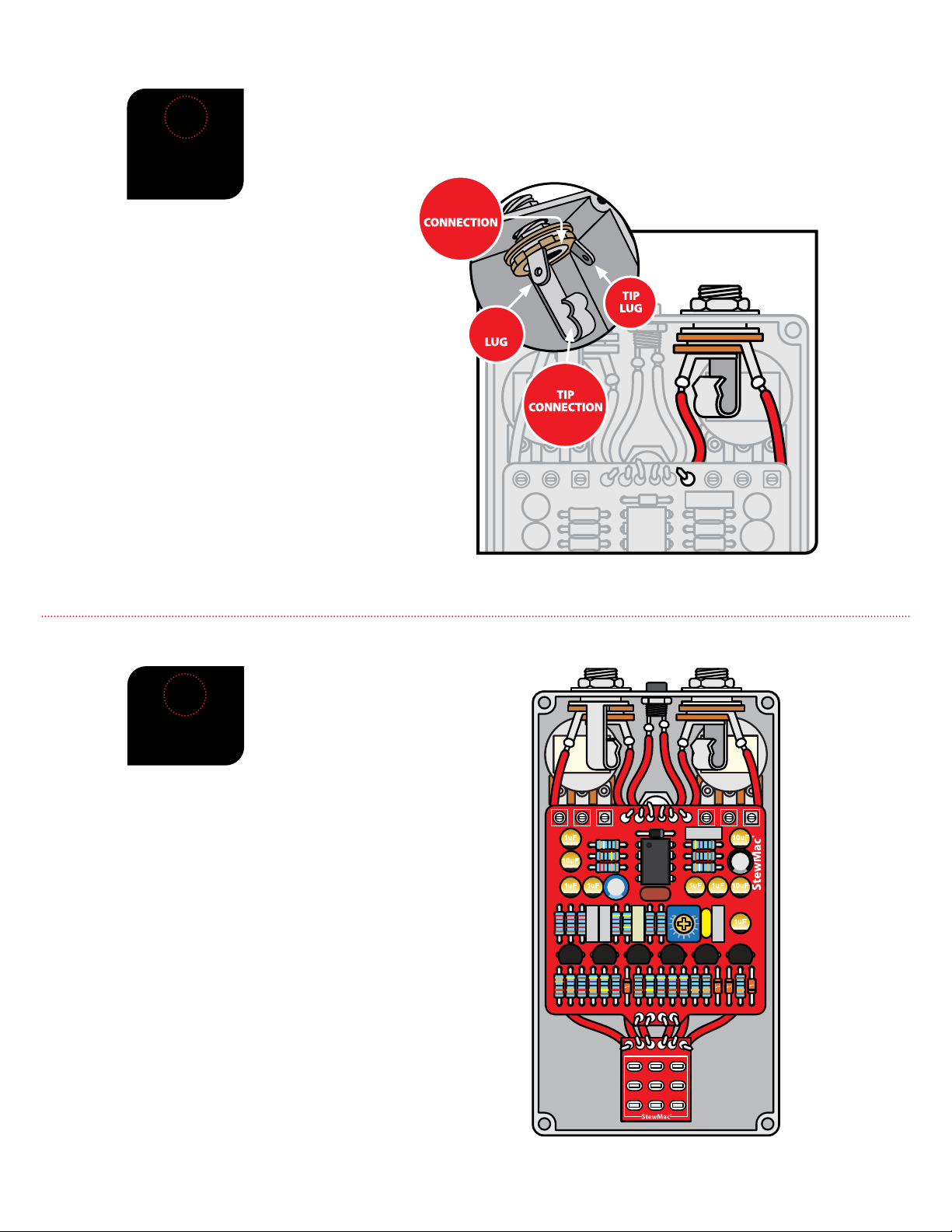
INSTALL
THE INPUT
JACK
16
Insert the DC power jack into the center hole in the top of the enclosure making sure
the longer of the two lugs is on the left. Use a 14mm wrench on the included nut to
secure the jack into the enclosure.
Solder the inside left wire to the longer lug of the DC jack.
Solder the inside right wire to the shorter lug of the DC jack.
SLEEVE
SLEEVE
Insert the input jack into the left side hole in the top of the enclosure with the tip
connection facing down, as shown in the diagram. Add the washer, and thread the nut
onto the shaft enough so that the pot can rotate freely. You may need to rotate the jack
to provide easier access to setting the solder joints.
Solder the left-most wire at the top of the printed
circuit board to the input jack lug that corresponds
with the sleeve connection. The sleeve lug should
be the one closer to the DC jack.
Solder the 4" wire on the left side of the breakout
board to the lug of the input jack that corresponds
with the tip connection. The tip lug should be the
one closer to the outside wall of the enclosure.
Once the solder has cooled, orient the jack as
shown in the diagram, making sure none of the
connections on the jack are touching any other
components, and tighten the nut on the jack.
16
22nJ
47nJ
22nJ
47nJ
33nJ
TL071
1uF 10uF
10uF
1uF 1uF 1uF 1uF
08 EDT
10uF
1uF
IN GND SW OUT
17
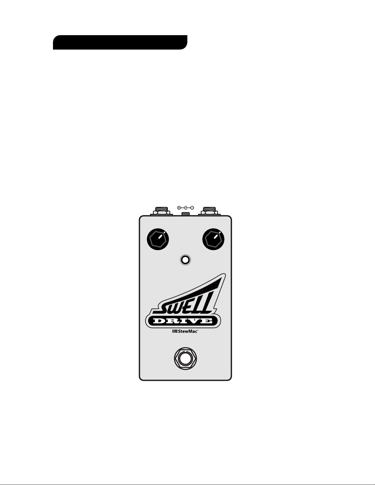
INSTALL
THE OUTPUT
JACK
Insert the output jack into the right side hole in the top of the enclosure with the tip
connection facing up, as shown in the diagram. Add the washer, and thread the nut
onto the shaft enough so that the jack can rotate freely. You may need to rotate the
jack to provide easier access to setting the solder joints.
Solder the right-most wire at the top of the
printed circuit board to the output jack lug
that corresponds with the sleeve connection. The
sleeve lug should be the one closer to the DC jack.
Solder the 4" wire on the right side of the
breakout board to the lug of the output jack that
corresponds with the tip connection. The tip lug
should be the one closer to the outside wall of the
enclosure.
Once the solder has cooled, orient the jack as
shown in the diagram, making sure none of the
connections on the jack are touching any other
components, and tighten the nut on the jack.
Shield lug Tip connection
Tip lugShield connection
SLEEVE
SLEEVE
COMPLETED
VIEW
18
With the output jack secured, this is what your pedal
should look like.
Congrats on a job well done.
Now, simply attach the bottom of the enclosure with
the included screws, plug it in and bend some tone!
17
POWER: Use a standard 9 volt DC power supply with a 2.1mm negative-center barrel (not included).
We always recommend pedal-specic, transformer-isolated, wall-wart power supplies or supplies with
separate isolated outputs. Pedals will make extra noise if there is ripple or unclean power. Switching-type
power supplies, daisy chains, and non-pedal specic power supplies do not lter dirty power as well and
let through unwanted noise. Do not run at higher voltages! Current draw is 25mA.
SENSITIVITY: Controls the decay of the eect. With a low sensitivity setting you will have to wait longer
for the sound to decay before playing another note will evoke the swell eect.
ATTAC K: Controls how fast the sound swells after the signal hits the circuit of the pedal. A lower attack
setting will produce a very long swell eect, a higher attack setting will produce a much faster swell.
INPUT
OUTPUT
9V DC
A
T
T
A
C
K
S
E
N
S
I
T
I
V
I
T
Y
HERE’S HOW THE CONTROLS WORK
Other StewMac Music Pedal manuals

StewMac
StewMac SCREAMER Manual

StewMac
StewMac Monarch User manual

StewMac
StewMac JHS 808 User manual

StewMac
StewMac NYC BIG MUFF PI User manual

StewMac
StewMac EC EXPANDER PEDAL KIT Manual

StewMac
StewMac SUN FUZZ Manual

StewMac
StewMac INTERVAL FUZZ Manual

StewMac
StewMac MXR PHASE 90 User manual

StewMac
StewMac TWO KINGS BOOST DOUBLE-POWERED ROYAL TONE Manual

StewMac
StewMac TAPE OP DELAY Manual


