StewMac LIGHTCYCLE PHASOR II Manual

1

2
BASED ON THE MU-TRON PHASOR II
FIRST TIME BUILDING A PEDAL? Kick back and watch our 4-part
series where we show you the basics of pedal building. Even if
you’re a complete beginner don’t worry! We go over everything
from unboxing, to choosing the right soldering iron, to making
every connection. We also give tips on painting your pedal.
Visit: stewmac.com/pedal-build
The Lightcycle is a phase shifter based on the rare Mu-Tron Phasor II, the stripped-down second-
generation version of the original Bi-Phase pedal.
The phase pedal duplicates the original signal and manipulates it by shifting the phase of the copied
signal. These types of eects originated in the studio with the birth of automated double tracking in the
60’s. Engineers would run two tape machines at varying speeds to achieve a double tracking eect that
produced a wide range of never before heard eects.
The Phasor II had a more simple and stage friendly control layout than the Bi-Phase that was easier to
manage in live performance situations. As of this writing, the Mu-Tron Phasor II fetches no less than
$700 on the used market.
3
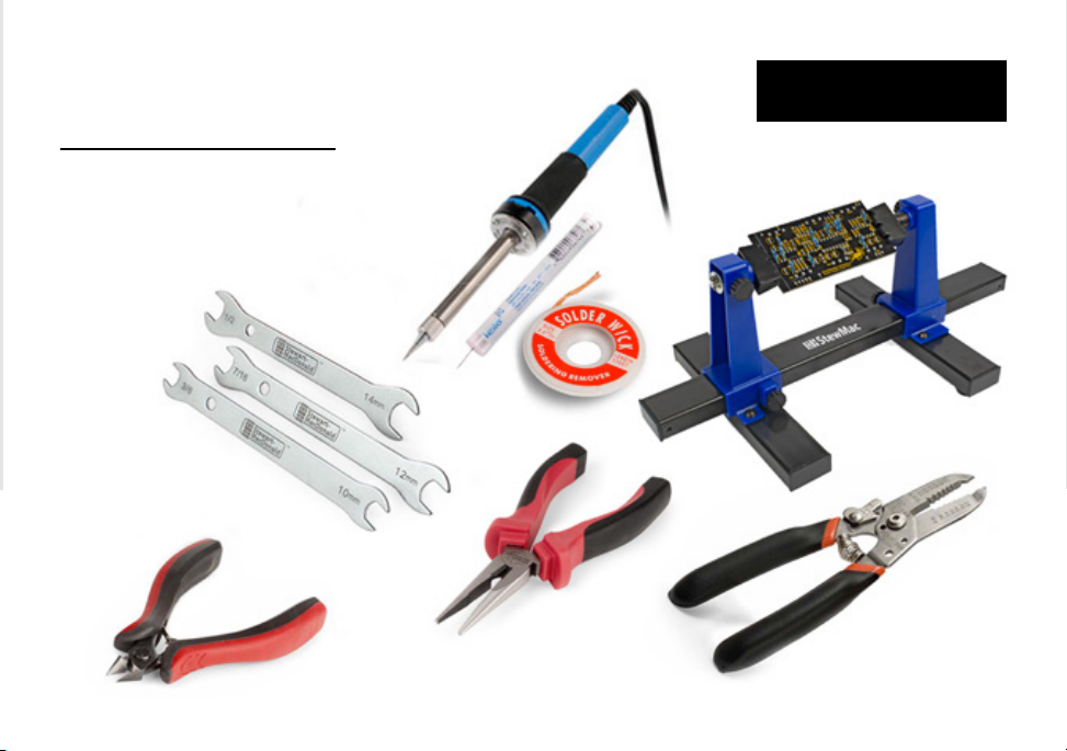
Soldering Iron #0502
Solder Wick #0504
Solder #0505
Wire Cutter #1607
Long-Nose Pliers #1610
Fine-Gauge Wire
Stripper #1606
Guitar Tech
Wrench Set #3691
or nut drivers/sockets
PC Board Holder #0500
TOOLS AND SUPPLIES
REQUIRED OR RECOMMENDED
Not pictured: #1Phillips screwdriver,
supplies to paint your pedal, clear
silicone adhesive, spray nish.
Power: Model 12253 requires a
standard 9V DC center-negative
power supply (not included) and
consumes less than 100mA.

4
Magnifying glass or
OptiVISOR #1685
Multimeter PM16B #3607
Our Pedal BuildingTool Set #2318 is the
perfect companion for new pedal builders
who do not already have a lot of tools and supplies.
TOOLS AND SUPPLIES
HELPFUL
Soldering Aids #0521
5
We know you are excited to get started building.
That said, one of the keys to a successful build, is
taking the time to get to know all of your parts. Sort all of your pedal’s
parts and check o according to the parts lists that follow. If you are not
familiar with what they do, the next section will give you a little primer.
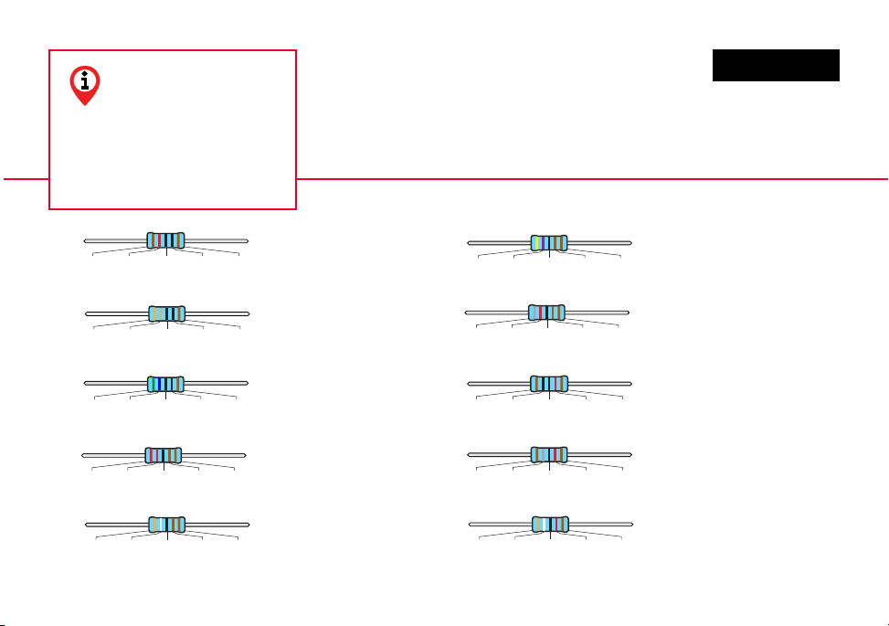
3.9K resistor (2) #100700
2.2K resistor (2) #7376
39K resistor (1) #100704
8.2K resistor (3) #100702
560Ω resistor (2) #7356
18K resistor (1) #7396
Green Blue Black Black Brown
Gray Red Black Brown Brown
Orange White Black Red Brown
Red Red Black Brown Brown
Orange White Black Brown Brown
Brown Gray Black Red Brown
120Ω resistor (1) #101122
Brown Red Black Black Brown 4.7K resistor (16) #7359
10K resistor (3) #7362
Brown Black Black Red Brown
Yellow Purple Black Brown Brown
330Ω resistor (1) #7375
Orange Orange Black Black Brown
PARTS LIST
Note: While electrical
properties remain the same,
the appearance of parts may vary
based on availability. If you are ever
unsure, please contact us via the
information on the back of this manual.

6
1N5817 rectier diode (1)
#7522
68K resistor (3) #7380
220K resistor (7) #7381
47K resistor (2) #7369
390K resistor (2) #7419
1N4148 rectier diode (2)
#7470
Orange White Black Orange Brown
Yellow Purple Black Red Brown
Red Red Black Orange Brown
Blue Gray Black Red Brown
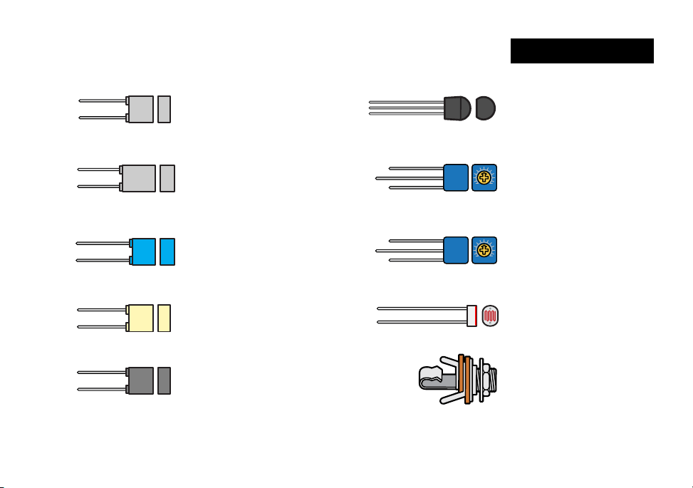
820pF capacitor (1)
#100722
47pF capacitor (1)
#100720
1µF capacitor (1)
#7314
10µF capacitor (3)
#7310
10uF
220µF capacitor (1)
#101930
220uF
1uF
PARTS LIST CONT
7
1N5817 rectier diode (1)
#7522
68K resistor (3) #7380
220K resistor (7) #7381
47K resistor (2) #7369
390K resistor (2) #7419
1N4148 rectier diode (2)
#7470
Orange Gray Black Orange Brown
Brown Purple Black Red Brown
Red Red Black Orange Brown
Blue Gray Black Red Brown
1µF capacitor (1)
#7314
1uF
10µF capacitor (3)
#7310
100uF
220µF capacitor (1)
#100727
220uF
820pF capacitor (1)
#100722
47pF capacitor (1)
#100720
KE - 10720 LDR (6)
#100778
2N4401 transistor (1)
#100735
470nF capacitor (2)
#101932
1nF capacitor (1)
#101931
3.3nF capacitor (1)
#7303
3n3K
MMK
BF6
63-
100nF capacitor (2)
#7304
.1J63
6.8nF capacitor (6)
#100723
682J100
1K trim pot (1)
#100737
10K trim pot (1)
#7570
KE - 10720 LDR (6)
#100778
WMA
0,47
100-
470nK
WIMA
1000/100-
2N4401 transistor (1)
#100735
2N4
401
102 1H
103 1M
1/4" mono jack (2)
#4652
PARTS LIST CONT
8
3PDT latching footswitch (1)
#1611
Adhesive foam tape squares (4)
#7560
2.1mm DC power connector (1)
#7468
White LED (1)
#7422
Yellow LED (1)
#7423
5mm LED mounting bezel (1)
#7432
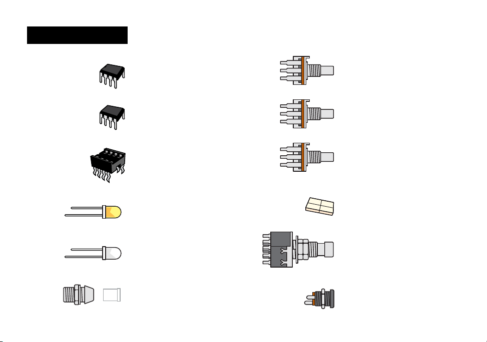
B10K linear taper pot (1)
#7532
A10K audio taper pot (1)
#101646
A25K audio taper pot (1)
#102230
TL072
TC1044 SCPA Charge pump (1)
#100732
Integrated circuit socket (7)
#7484
TL072 1C op-amp (6)
#7444
TC1044
PARTS LIST CONT

9
StickerSheet (1)
Circuit Board [PCB] (1)
Breakout Board (1)
Pre-drilled enclosure (1)
IN GND SW OUT
24" of lead wire (1)
#5960
Control knobs (3)
#7501
PARTS LIST CONT
10
1. To minimize redoing steps, make
sure you have a solid idea of the
look and feel you’re going for.
2. Lightly sand housing with a
P240 grit sandpaper and wipe
clean any debris.
3. Cover the holes from the
inside with masking tape.
4. On a large piece of cardboard,
elevate the housing top and
bottom on a couple of small blocks
of wood.
5. With long, slow strokes, spray
one light coat of primer or primer/
paint on top and bottom. Allow
45 minutes of drying time between
next two to three coats.
6. If you’re using primer followed
by paint method, paint 3 coats
with 45 minutes between coats.
7. Now, add your Lightcycle
sticker and any other
desired decoration (paint
pens, acrylic paint, Sharpie
etc.). Allow drying time.
8. Add 3 coats of clear coat glaze
with 45 minutes between
coats. Wait at least 2 hours
before adding parts.
Give your pedal a custom paint job by painting and adding the stickers provided in this kit
(or custom decals that you can create on your own). Doing this pre-build is not only fun,
but it’s much easier than disassembling the pedal to paint it once you put it together. Don’t
forget to order quality primer and lacquers from stewmac.com.
PAINTING
YOUR PEDAL
HOUSING
11

11
If you’re having trouble reading the color bands, there
are apps that make easy work of identifying them. Or, try
using a multimeter to read a resistor’s value. Just set your
multimeter to ohms and connect the test leads on each
side of the resistor.
A number of dierent components are used to make an
eects pedal. Here’s an overview of what they do..
RESISTORS
A resistor is used in an electrical circuit to present an
opposition to current ow. It resists the amount of
current that can pass through it.
A resistor’s value—the amount of resistance it creates—
is rated in ohms (). The higher the ohmic value, the
greater the resistance to this ow of current. For
example, a 100 resistor creates ten times as much
resistance as a 10 resistor.
Resistor values are indicated by colored bands, read from
left to right. The rst color in the code is usually the one
painted closest to a lead. When a gold or silver band is
present, it’s always one of the last colors in the code.
UNDERSTANDING ELECTRONIC
COMPONENTS
4.7KΩ ±1%
K=1,000
Band 1 Band 2 Band 3 Multiplier Tolerance
4 7 0 x10 ±1% =5-band code:
4-band code: read Bands 1 and 2 same as above, then
Band 3 is the Multiplier and Band 4 is the Tolerance.
BLACK 0 0 0 1
BROWN 1 1 1 10 +/- 1%
RED 2 2 2 100 +/- 2%
ORANGE 3 3 3 1,000
YELLOW 4 4 4 10,000
GREEN 5 5 5 100,000 +/- 0.5%
BLUE 6 6 6 1,000,000 +/- 0.25%
VIOLET 7 7 7 10,000,000 +/- 0.10%
GRAY 8 8 8 100,000,000 +/- 0.05%
WHITE 9 9 9
1,000,000,000
GOLD 0.1 +/- 5%
SILVER 0.01 +/- 10%
11

12
Resistors and capacitors may also be referred to
with shorthand notation on the printed circuit
board when there is a decimal in the value. For
example, the place on the board for the 4.7K
resistor will read 4K7 and the spot for a 2.2nF
capacitor will read 2n2. This is done to save
space on the board and make the labels as clear
as possible.
Some capacitors have polarity and some don’t.
It’s extremely important to install polarized caps
correctly in a circuit. The negative lead will often
be indicated by a band of arrows pointing to
the negative lead and will be shorter than the
positive lead. The positive lead of an electrolytic cap
will be longer and won’t have any arrows pointing to it.
Installing capacitors with the polarity backwards will
make the circuit malfunction and quickly destroy the
capacitor— even causing it to explode.
CAPACITORS
The two main uses of capacitors are to store electricity
and to block the ow of DC current.
Capacitor values are typically printed on the
component. The key values with caps are their voltage
and capacitance.
The voltage spec for a cap refers to how much DC
voltage it can handle at any given time. If this rating is
exceeded, the capacitor will fail.
Capacitance, measured in farads, refers to how
much electricity a capacitor can hold. One farad (1F)
would be much too large for use in a pedal. Caps
for pedals are rated between millionths of a farad,
called microfarads (F), billionths of a farad, called
nanofarads (nF), or trillionths of a farad: picofarads
(pF). .001μF = 1nF = 1,000pF.
12
1
0
1
J
1
00V
1
02J
1u F
.1J63
++
The hole in the PCB for the positive lead
is square and marked with a“+”.
+
10U

13
12
TRANSISTOR
Transistors are used
to amplify electrical
signals. They have
a square tab on
one side. Be sure to
match the tab to the
outlined tab shown
on the circuit board
when installing.
INTEGRATED CIRCUITS
Integrated circuits are
complex, tiny, self-
contained collections
of components that
contain a complete
circuit. Op-amps, audio
processors, and linear
voltage regulators are
three kinds of
integrated circuits.
DIODES
Diodes are used where you want electricity to ow in
only one direction, such as power rectication, and
also to limit how much current can ow, to create
“clipping” distortion.
Diodes are also polarized, so they need to be installed
in the correct orientation. The stripe around one end
marks the negative (minus) lead of the diode. On the
circuit board, the printed outline of the diodes also
shows this stripe. Install each diode so that its stripe
matches the direction shown on the circuit board.
2n2J630
TL072
PT2399
PT2399
PT2399
PT2399
echo audio
processor (1) #7490
TL072CP TL072CP
low noise
op-amp (1) #7444
13
2N4401

14
POTENTIOMETER
A potentiometer, or pot, is a variable
resistor. This means as the knob shaft
is rotated, the DC resistance
will change. There are three
lugs or soldering terminals on a
conventional potentiometer. The
outside two are the ends of the
resistive strip, and the center lug
is connected to the “sweeper.”The
sweeper allows you to vary the DC
resistance relative to its position along the resistive
strip, or relative to the outer two
lugs.
Potentiometers come in
two varieties, linear-taper
and audio-taper. The linear-
taper pot’s taper works at a 1:1
ratio. Audio taper, has a special
logarithmic ratio.
Audio taper is used because our ears don’t hear
changes in volume in a linear fashion as you might
expect. As the volume increases, a greater change
in signal or sound-pressure is required to perceive a
smooth transition.
LED
LED stands for Light Emitting Diode,
and functionally LEDs are very similar to
regular diodes. LEDs are most often
used as indicator lights in pedals. They
are polarized just like diodes and
electrolytic capacitors and must be
installed in the correct orientation to
work. The positive (anode) lead of the LED
will be longer and the anode side of the
LED housing will be round. The negative
(cathode) lead of the LED will be shorter
and the cathode side of the LED housing
will be at. LEDs are mounted inside
of a bezel, which protects the LED and
insulates the leads from shorting against
the enclosure or any internal components.
14
15
The solder joints you’ll make on the circuit boards
are very small, and too much heat can damage the
board. The idea is to make joints quickly, without scorching the holes.
SOLDERING Here’s a few more
soldering tips that
might be helpful:
• Keep your soldering tip
clean by wiping it often on
a damp sponge.
• Also keep it tinned by
occasionally melting a little
solder onto it.
• Don’t blow on the hot
solder or touch anything
until the joint has cooled
completely. A good solder
joint is shiny – a sign that it
was left to cool undisturbed.
• Plan so each joint is only
soldered once. Resoldered
joints are messy and more
likely to fail.
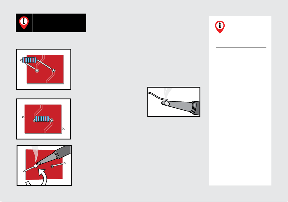
1. Hold components in place for soldering by
threading the leads through the board and bending
them apart on the reverse side. You will be making
your solder joints on the reverse side of the board.
2. Tin the iron by melting a
small amount of solder onto
the tip of the iron.
3. Insert the tip into the hole and let it heat for 4-5
seconds before touching it with solder. This heats the
contact enough for the solder to ow nicely without
damage. Feed the solder to the hole, not the iron, and
you don’t need much solder, just enough to ll the
hole. Keep the iron on the connection for a second
longer; this pause gives time for all of the ux to cook
out of the joint. After the joint has cooled, trim away
the excess lead wire.
15
16
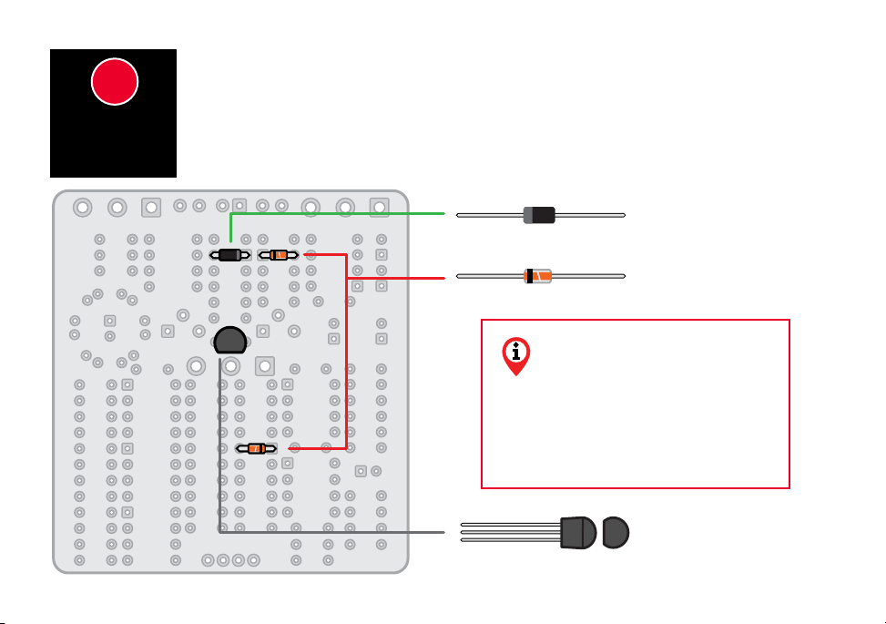
1N5817 rectier diode (1)
#7522
1N4148 rectier diode (2)
#7470
2N4401 transistor (1)
#100735
2N4
401
Insert the diode leads through the component side (the side with the component’s info
silkscreened in white). In many cases, components must be inserted in a specic direction due
to polarity, so follow the graphics carefully. For example, diodes are polarized, so they must
be installed in the correct orientation. Install the diodes and transistor. Solder the diodes and
transistor on the opposite side of the board, known as the solder side.
Note the stripe around one end of the diode.
This marks the negative (minus) lead. On
the PCB, the printed outline of the diodes also
shows this stripe. Install each diode to match the
direction shown. Place all diodes with the wires
pointing down, through the component side.
INSTALL
3 DIODES &
1TRANSISTOR
22
17
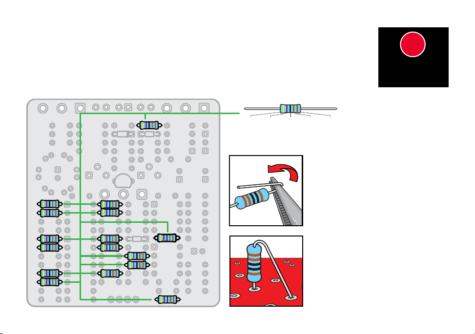
4.7K resistor (16) #7359
Yellow Purple Black Brown Brown
Next, we’re going to add some resisitors to our PCB. Like in the previous step, you’ll nd an
outline of each resistor and its value printed in the proper location on the PCB. Resistors
are not polarized, so it doesn’t matter which lead goes in which hole. Match resistors to the
values on the PCB, a few at a time, and solder in place. Clip the leads close to the board, but
not touching the board so you don’t damage the solder pads.
Install resistors upright
This circuit is a tight t for many of the
components. To make sure they all
t and clear one another, install the
resistors vertically in columns.
Holding a resistor vertically in your
ngers, bend the lead on the top
end down approximately 135°. This
will allow you to install the resistor
vertically easily and quickly into the
board as shown. Needle nose pliers
make easy work of the job, but you can
also bend the lead with your ngers.
INSTALL 46
RESISTORS
33

18
33
39K resistor (1) #100704
8.2K resistor (3) #100702
18K resistor (1) #7396
Gray Red Black Brown Brown
Orange White Black Red Brown
Brown Gray Black Red Brown
10K resistor (3) #7362
Brown Black Black Red Brown
560Ω resistor (2) #7356
Green Blue Black Black Brown
120Ω resistor (1) #101122
Brown Red Black Black Brown
330Ω resistor (1) #7375
Orange Orange Black Black Brown
INSTALL 46
RESISTORS

19
68K resistor (3) #7380
220K resistor (7) #7381
47K resistor (2) #7369
390K resistor (2) #7419
Orange White Black Orange Brown
Yellow Purple Black Red Brown
Red Red Black Orange Brown
Blue Gray Black Red Brown
3.9K resistor (2) #100700
2.2K resistor (2) #7376
Red Red Black Brown Brown
Orange White Black Brown Brown
INSTALL 46
RESISTORS
33
When installing resistors vertically, use care to install them in an
orderly fashion in rows for a nice and consistent look.

20
102 103
1K trim pot (1)
#100737
102
10K trim pot (1)
#7570
103
INSTALL 2
TRIM POTS
44
The internal trim pots featured on the Lightcycle allow the user to ne tune the overall“feel”
the pedal will have when engaged. The trim pot on the left adjusts the sweep, or general
feel of the eect when it is engaged. The trim pot on the right adjusts the the strength of the
eected signal.
Carefully insert the legs of the trim pots into the PCB
and solder in place on the back of the PCB.
On page 38, we will show you how adjustments to the
trim pots will aect your sound.
Table of contents
Other StewMac Music Pedal manuals

StewMac
StewMac SUN FUZZ Manual

StewMac
StewMac SWELL DRIVE Manual

StewMac
StewMac SCREAMER Manual

StewMac
StewMac FAN TREMOLO Manual

StewMac
StewMac EC EXPANDER PEDAL KIT Manual

StewMac
StewMac TAPE OP DELAY Manual

StewMac
StewMac Disaster Transport User manual

StewMac
StewMac INTERVAL FUZZ Manual

StewMac
StewMac TWO KINGS BOOST DOUBLE-POWERED ROYAL TONE Manual

StewMac
StewMac NYC BIG MUFF PI User manual


