6
called nanofarads (nF), or trillionths of a farad, called
picofarads (pF). .001μF = 1nF = 1,000pF.
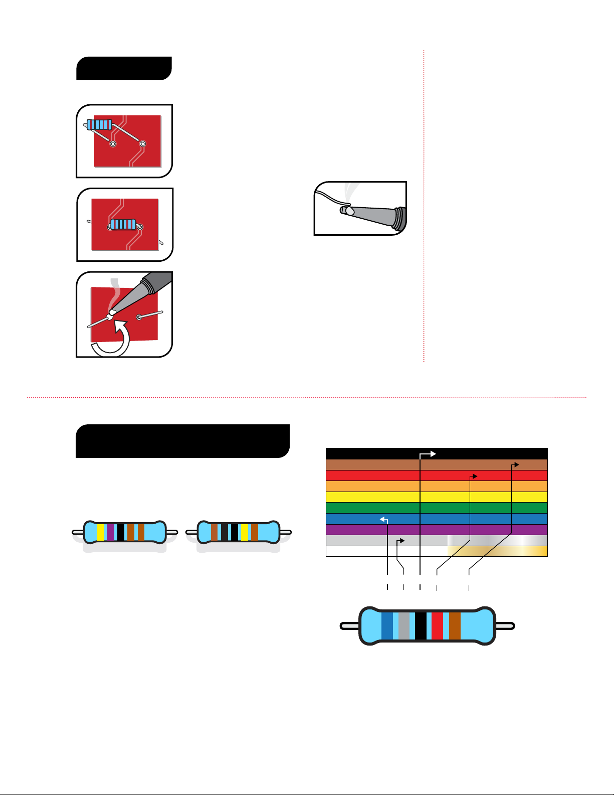
Resistors and capacitors may also be referred to with
shorthand notation on the printed circuit board
when there is a decimal in the value. For example,
the place on the printed circuit board for the 4.7K
resistor will read 4K7 and the spot for a 2.2nF
capacitor will read 2n2. This is done to save space on
the board and make the labels as clear as possible.
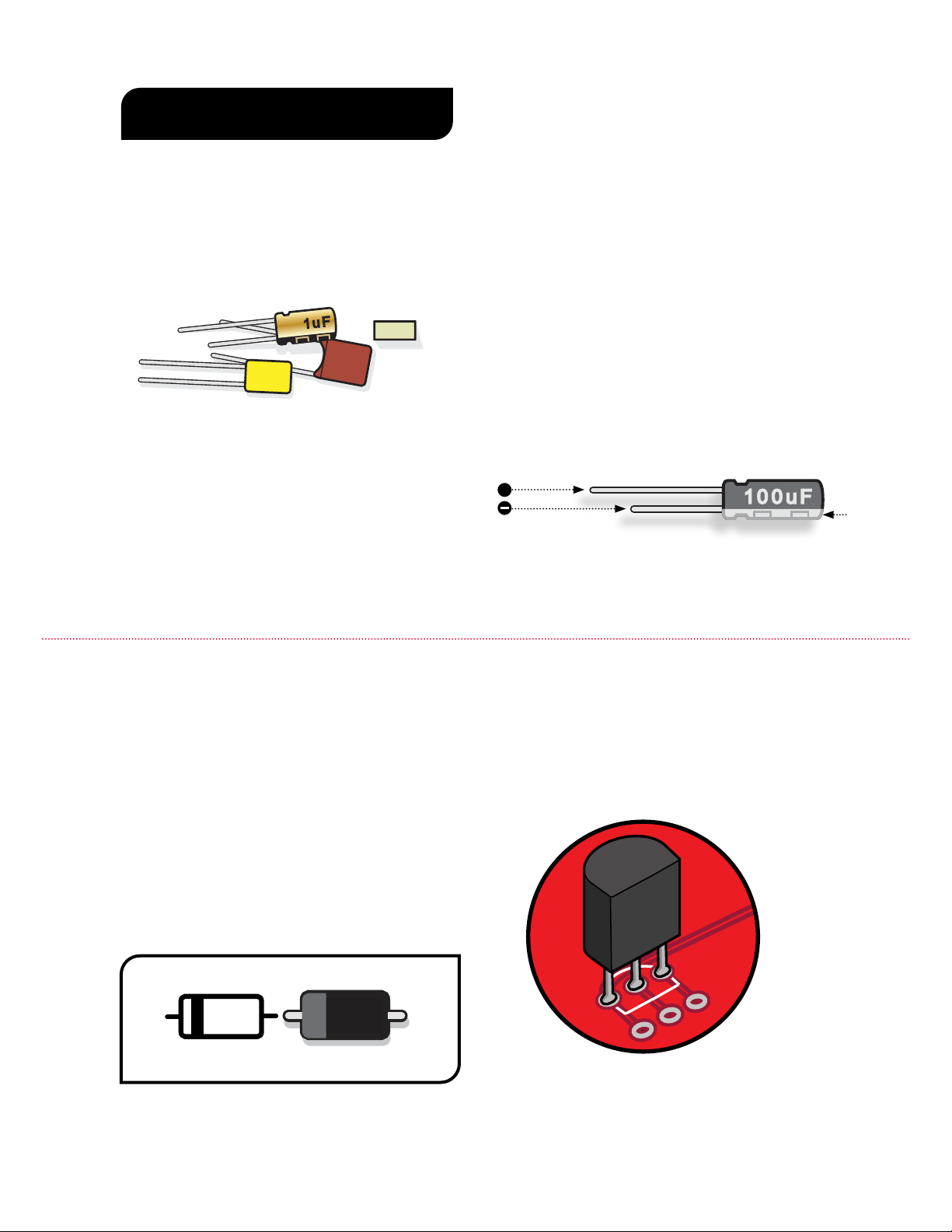
Some capacitors have polarity and some don’t.
It’s extremely important to install polarized caps
correctly in a circuit. The negative lead will often
be indicated by a stripe on the negative lead’s side
(often with arrows) and will be shorter than the
positive lead. The positive lead of an electrolytic cap
will be longer and won’t have the stripe on that side.
Installing capacitors with the polarity backwards will
make the circuit malfunction and quickly destroy the
capacitor—even causing it to explode.
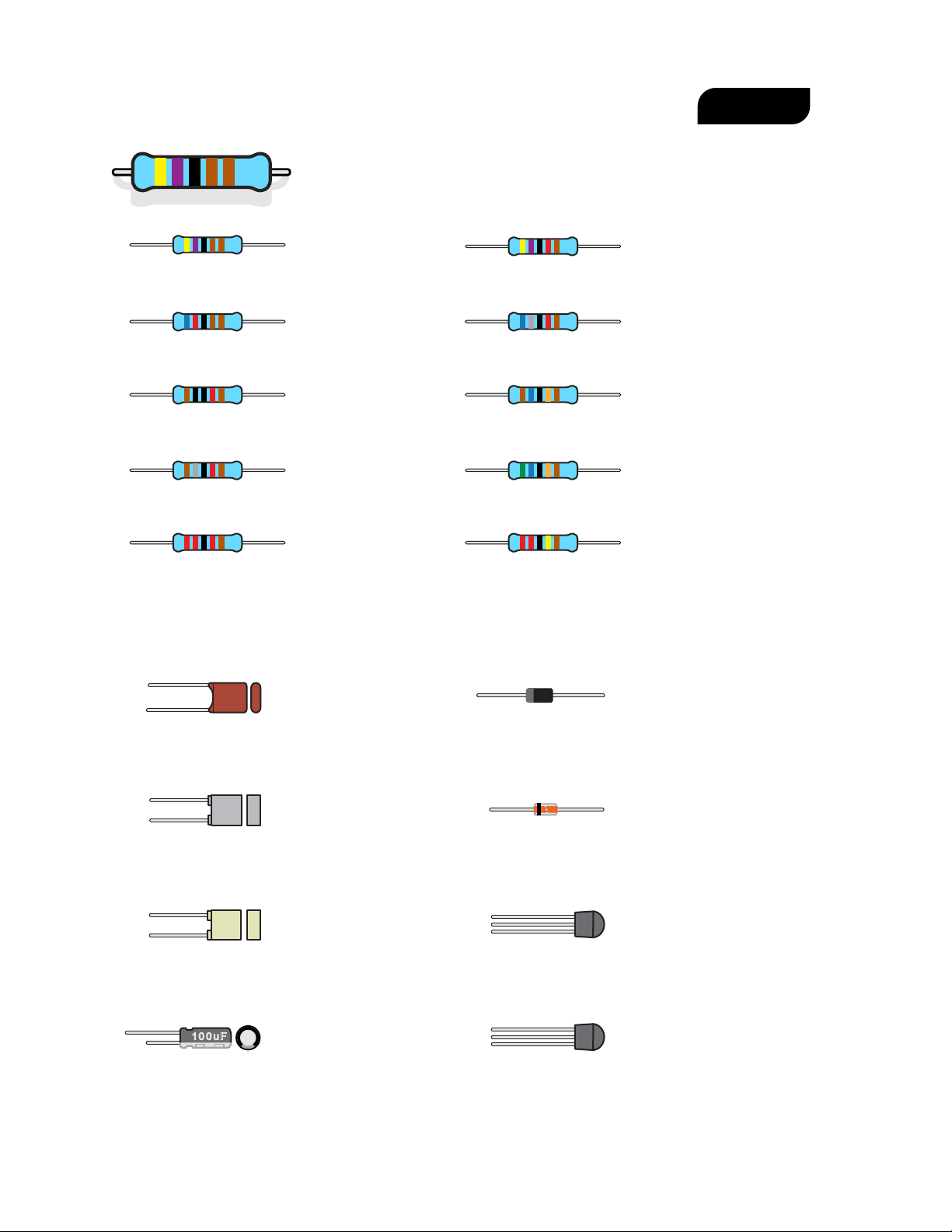
CAPACITORS
The two main uses of capacitors are to store
electricity and to block the ow of DC current.
Capacitor values are typically printed on the
component. The key values with caps are their
voltage and capacitance.
The voltage spec for a cap refers to how much DC
voltage it can handle at any given time. If this rating
is exceeded, the capacitor will fail.
Capacitance, measured in farads, refers to how
much electricity a capacitor can hold. One farad
(1F) would be much too large for use in a pedal.
Caps for pedals are rated between millionths of a
farad, called microfarads (F), billionths of a farad,
101J
100V
102J
1u F
.1J63
++
UNDERSTANDING ELECTRONIC
COMPONENTS
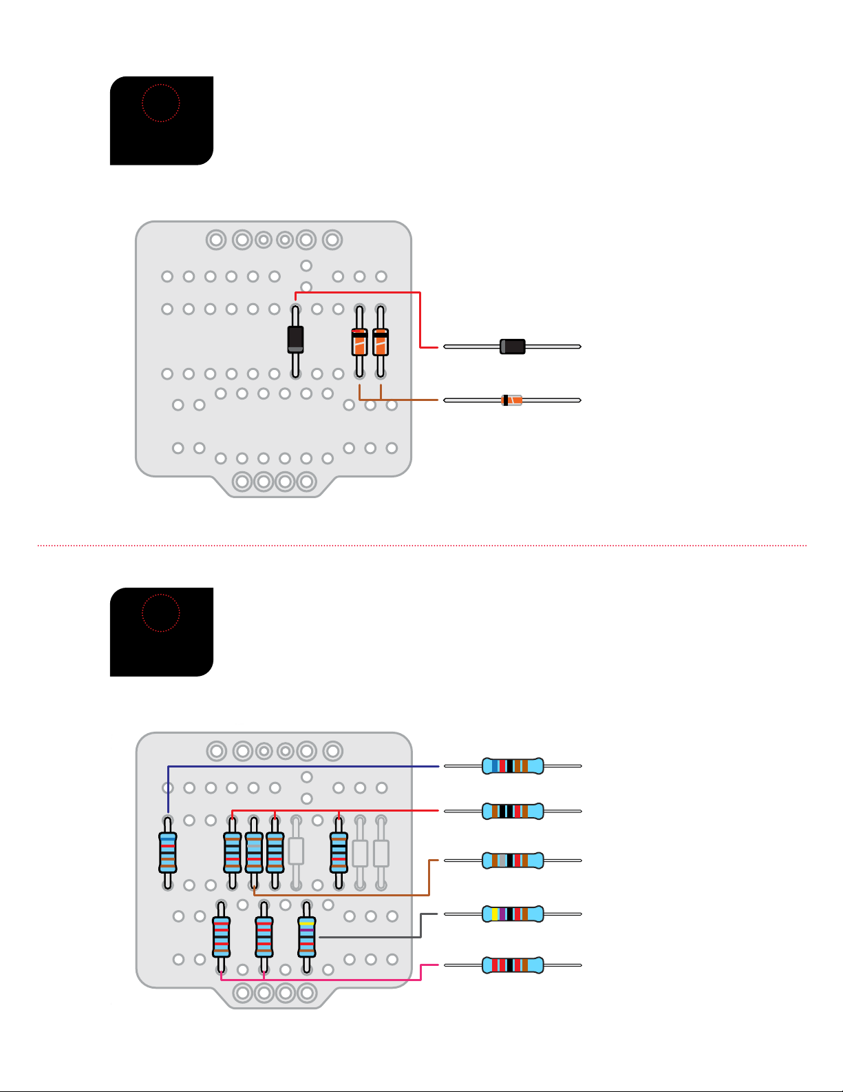
DIODES
Diodes are used where you want electricity to ow
in only one direction, such as power rectication,
and also to limit how much current can ow, to
create “clipping” distortion.
Diodes are also polarized, so they need to be
installed in the correct orientation. The stripe
around one end marks the negative (–) lead of the
diode. On the printed circuit board, the printed
outline of the diodes also shows this stripe. Install
each diode so that its stripe matches the direction
shown on the printed circuit board.
stripe
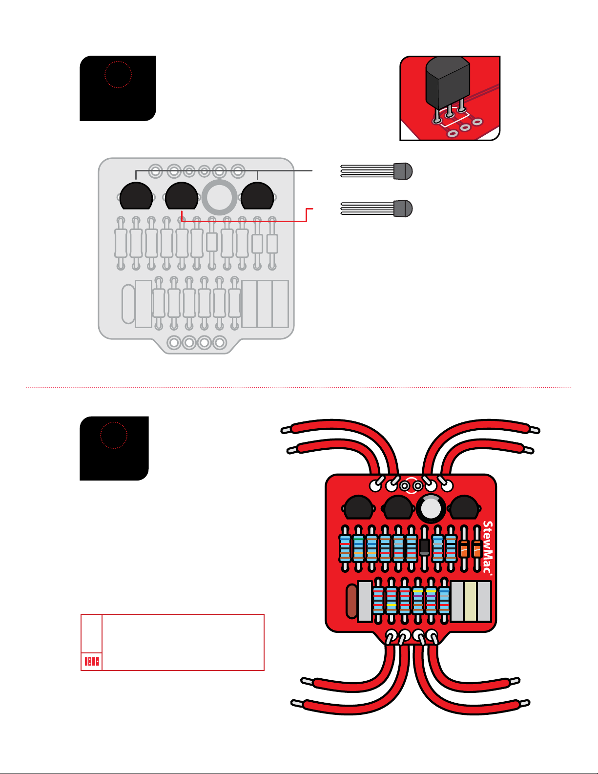
TRANSISTORS
Transistors are used to amplify electrical signals.
They have a at side and a round side. The location
on the printed circuit board also has a at side
and a round side. Match the orientation of the
component to this outline.