StewMac NYC BIG MUFF PI User manual
NYC BIG MUFF PI
TONE BYPASS MOD
INSTRUCTIONS
WITH THIS MOD
YOU'LL KEEP
YOUR MIDS AND
GET ALL THE FUZZ
YOU WANT. It's a necessary
mod for anyone who loves the BMP, but dislikes the
way it scoops the middle frequencies of your tone.
This switch was a feature on the 1970's Big Mus,
but was not included in the 2000's "reissues" of the
pedal. This mod is only intended for the big box NYC
Big Mu Pi pedals released in the 2000's.
If you run into issues with this modication,
a StewMac tech advisor is a click or call away:
stewmac.com/contactus or 1.800.848.2273
Big Mu is a registered trademark of New Sensor Corp.

Guitar Tech Screwdriver
and Wrench Set
#3693
1/4" Drill Bit
#4850
Kester Pocket-Pak Solder
#0505
Solder Sucker
#0503
Solder
Wick
#0504
PARTS LIST
[1] Black and white
pushback wire
[2] 1/8" heat shrink - 2" length
[1] Mini toggle switch
[1] NYC Big Mu Pi Tone Bypass
Mod instructions
Fine-gauge
Wire Stripper
#1606
Wire Cutter
#1607
Solomon SR-965
Soldering Station
#0502
TOOLS YOU’LL NEED
CONNECTING THE NEW SWITCH
For your new switch to be connected properly, an understanding of tinning and soldering is necessary.
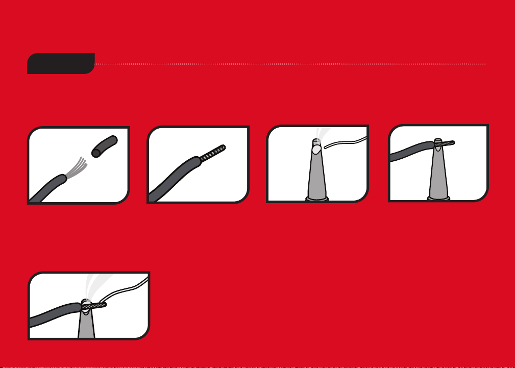
TINNING
Tinning is an important part of the soldering process as it helps to make stronger solder joints. Tinning a
wire is done by heating the wire with a soldering iron and then melting a layer of solder on it. If the wire
you plan to tin is made up of many strands of wire, follow all of the steps below.
1. Strip roughly 1/4"of
the wire sheathing from
the end of the wire you
intend to solder.
2. Twist the wire
strands of the exposed
wire rmly. Don’t twist
solid core wires.
3. Dab a tiny amount
of solder onto the end
of your soldering iron.
4. Touch the soldering
iron with its dab of
solder to the exposed
wire closest to the
sheathing. This will help
to hold the iron in place
as it heats the exposed
wire. Wire will heat
within a few seconds.
5. With the iron still touching the wire, take a
length of solder and touch it on the exposed end
of the wire and slide it along the wire slightly
towards the sheathing and iron. The solder will
nd its way into the braids of the exposed wire.

MORE HELPFUL
SOLDERING TIPS
AND TRICKS
•Keep your
soldering tip clean
by wiping it often
on a damp sponge.
• Also keep it tinned by
occasionally melting
a little solder onto it.
•Don’t blow on the
hot solder or touch
anything until the joint
has cooled completely.
A good solder joint
is shiny – a sign that
it was left to cool
undisturbed.
• Plan so each joint
is only soldered once.
Resoldered joints
are messy and more
likely to fail.
SOLDERING
1. Insert tinned wire through lug hole
before soldering and bend to secure.
2. Melt a small amount of solder onto
the tip of the iron (“tinning” the iron).
3. Hold the tip against the connection
until the connection reaches soldering
temperature. This should take just a
few seconds.
4. Feed solder to the connection, not
to the iron. Stop feeding solder once
the lug hole is lled. Keep the iron on
the connection for a second longer;
this pause gives time for all of the ux
to cook out of the joint. After the joint
has cooled, trim away the excess wires.

DESOLDERING
Much like soldering, you run the risk of damaging the circuit board while desoldering. If too much heat is
applied to a circuit board the solder pad can pull away from the board, breaking its electrical connection. A
solder sucker and solder wick are your best friends when desoldering. Here are a few tips on how to use them:
1. USE A SOLDER SUCKER
Depress the plunger on the solder
sucker to prepare it. Tin your
soldering iron, apply it to the
solder joint, and hold the solder
sucker a fraction of an inch away.
Within a few seconds, the joint
will liquefy. As soon as it does,
push the button on the side of
the solder sucker and remove
the soldering iron from the joint.
Inspect the solder joint and
repeat the process until all of the
solder is removed.
2. USING SOLDER WICK
Solder wick is a at, braided
wire that can be used to remove
solder from a joint. Simply place
the wick on the solder joint and
press your soldering iron against
the wick, heating the joint
through the wick. The solder will
liquefy and absorb into the wick.
Keep inching the wick down as
it absorbs solder so it does not
become saturated.
3. LIFT THE LEAD
Once the solder is removed from
the joint, use a pair of pliers to lift
the lead from the circuit board
contact. If the lead doesn’t want
to come up, heat the solder joint
up to liquefy the residual solder
which will free the lead. Once
the lead is lifted, use the solder
sucker or solder wick to remove
any leftover solder.

DISASSEMBLE THE PEDAL
Remove the four screws that
secure the back of the pedal
housing. As you are removing
the back panel, be careful not
to catch the circuit board on
any of the wires. If your pedal
has a glued LED light, do not
remove it. Pull the knobs o of
the front of the pedal, unscrew
the mounting nuts for the
potentiometers and the switch,
and unscrew the mounting nuts
for the instrument and power
jacks on the top panel. Set all of
the components to the side for
now.
AMPLIFIER
VOLUME TONE SUSTAIN
11
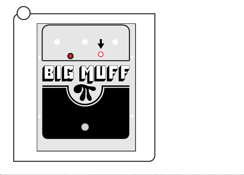
DRILL A HOLE FOR
THE NEW SWITCH
Use a 1/4" drill bit to drill a hole
in the pedal housing directly
between the tone and sustain
holes and just above the black
line (pictured). Measure the
location of the hole you will drill
and mark that location on the
underside of the housing. Drill
the hole from the underside of
the housing to avoid bending
the housing while drilling.
AMPLIFIER
VOLUME TONE SUSTAIN
22
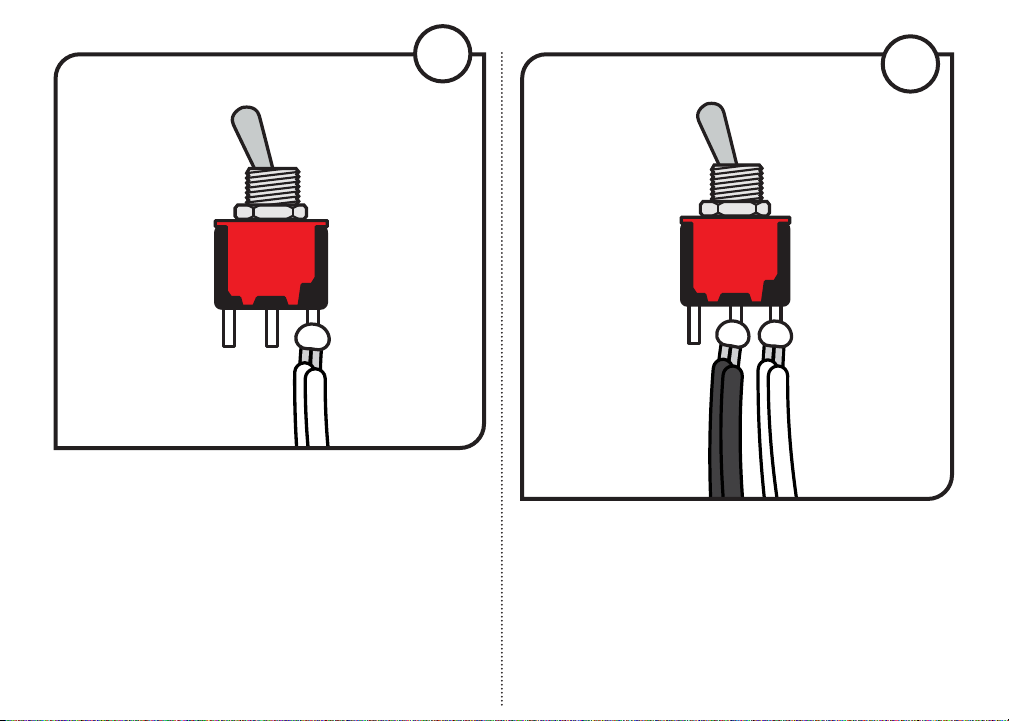
ATTACH BLACK WIRES TO SWITCH
Cut two 4" black jumpers, strip roughly 1/4" of
insulation from the end of the wires, and tin the
freshly exposed wire. Wrap the wires through the
eyelet of the middle solder lug on the switch and
solder them.
44
INSTALL JUMPERS ON THE SWITCH
Cut two 4" white jumpers, strip roughly 1/4" of
insulation from the end of the wires, and tin the
freshly exposed wire. Wrap the wires through the
eyelet of one of the outside solder lugs on the
switch and solder them. Even though it's called
”pushback wire” you must strip the insulation to
make a solid solder connection.
33

HEAT SHRINK SOLDER JOINTS
Add a 1" length of heat shrink to each solder joint
and use a heat source to shrink the insulation over
the solder joints and wires.
55TIPS ON HEAT SHRINKING
1. Heat shrink is used
to insulate an
electrical connection,
like a solder joint, to
prevent the connection
from shorting.
2. Slide the heat shrink
all the way up to the
switch, completely
covering the solder joint
and solder lug.
3. Wave the ame from
a lighter or the tip of a
soldering iron near the
positioned heat shrink
until the wrap constricts
to a rm hold. Allow
heat shrink to cool.

ADD HEAT SHRINK TO ONE LEG
Slide another 1" length of heat shrink over one of
the black wires that you just soldered to the new
switch.
77
66
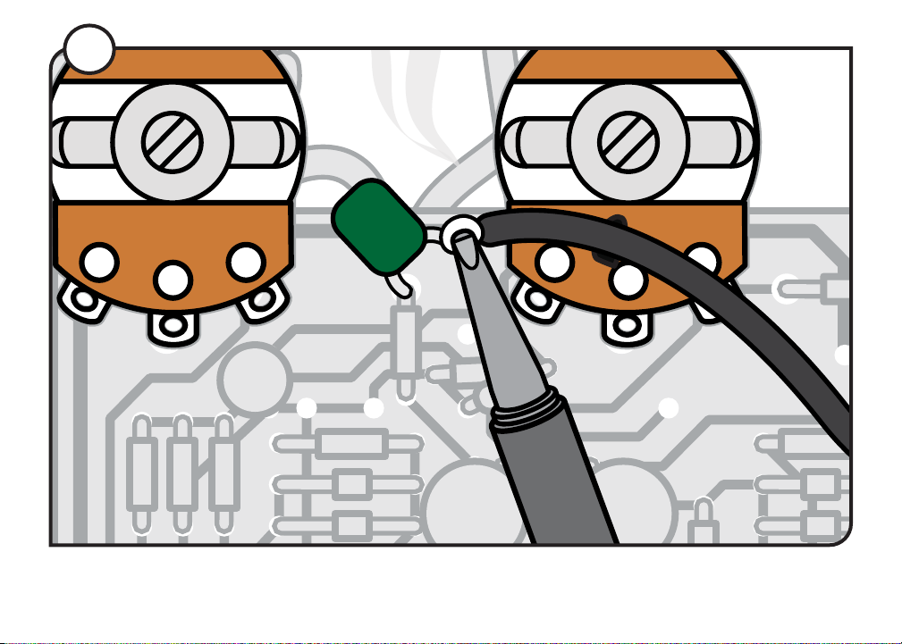
FIND CAPACITOR C8
The location of this capacitor varies by model. To
nd out which model you have, locate the version
code. The code (similar to “EC3003 REV B”) is printed
in large white letters along the bottom of the board.
The last letter in that code (A, B, C, D, or E) is the
version you have. Now locate capacitor C8. It will be
either yellow or green. On version A or B, C8 will be
located between the volume and tone pots. On this
version, desolder and lift the leg of C8 that is closest
to the edge of the board. On version C, D, or E, C8
is located between the tone and sustain pots. On
this version, desolder and lift the leg of C8 that is
closest to the sustain pot.
Circuit board ipped
C8
88
ATTACH BLACK WIRE TO C8
Solder the free end of the same black wire to the lifted leg of C8.
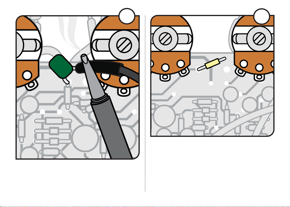
HEAT SHRINK SOLDER JOINT
Slide the heat shrink over the new solder joint
and use a heat source to shrink the insulation to
the joint.
Circuit board ipped
C8
99
FIND RESISTOR R5
If your Big Mu is version A or B, it will be located
between the tone and sustain pots. On version C, D,
or E, it will be located just below capacitor C8. For
all versions, locate the leg closest to the sustain pot
and desolder and lift it.
Circuit board ipped
C8
R5
1010

ATTACH BLACK WIRE TO R5
Slide another 1" length of 1/8" diameter heat shrink
over the second black wire that you just soldered
to the new switch. Solder the free end of the same
black wire to the lifted leg of R5.
Circuit board ipped
C8
R5
1111
HEAT SHRINK SOLDER JOINT
Slide the heat shrink over the new solder joint and use
a heat source to shrink the insulation to the joint.
Circuit board ipped
C8
R5
1212
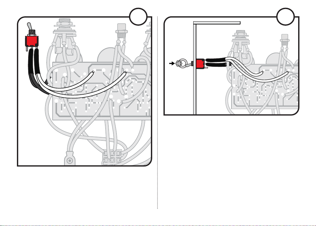
INSTALL THE WHITE WIRES
Solder the free end of one of the white wires to the
hole vacated by the lifted leg of C8, and solder the
free end of the other white wire to the hole vacated
by the lifted leg of R5.
REASSEMBLING AND TESTING
Install the new switch into its hole rst, and then
reinstall the rest of the components back in to the
pedal housing. Re-attach the back panel with the
four mounting screws. Plug in your guitar and an
amp, and take your Big Mu for a test drive. When
the tone bypass switch is engaged, the pedal
should be noticeably louder. If you experience
intermittent signal or other irregularities, pull the
back panel o the pedal again and inspect your
solder joints.
1313
Chassis side view
1414

21 N. Shafer St., Athens, OH 45701
800-848-2273 stewmac.com
©2019 StewMac. All rights reserved. • #2215 Updated December 2019
TECHNICAL SUPPORT:
If you have any questions before, during, or after
attempting these modications, please don't hesitate
to reach out to our Tech Support Team. They are
phone M-F 9:00AM-5:00PM ET at 1-800-848-2273.
DISCLAIMER: Performing the modications
outlined in these instructions will void any warranty
on your pedal. StewMac is not responsible for any
damage caused by attempting these modications.
Table of contents
Other StewMac Music Pedal manuals

StewMac
StewMac Disaster Transport User manual

StewMac
StewMac SCREAMER Manual

StewMac
StewMac TWO KINGS BOOST DOUBLE-POWERED ROYAL TONE Manual

StewMac
StewMac SUN FUZZ Manual

StewMac
StewMac SWELL DRIVE Manual

StewMac
StewMac FAN TREMOLO Manual

StewMac
StewMac INTERVAL FUZZ Manual

StewMac
StewMac TAPE OP DELAY Manual

StewMac
StewMac JHS 808 User manual

StewMac
StewMac LIGHTCYCLE PHASOR II Manual


Popular Music Pedal manuals by other brands


DIY
DIY REPLICA Series Assembly manual

PedalPCB
PedalPCB Canis Distortion quick start guide

Nady Systems
Nady Systems TS-30 owner's manual

Electronic Audio Experiments
Electronic Audio Experiments Dude Incredible Technical manual

MORLEY
MORLEY PCBES manual

Rainger FX
Rainger FX Dr FREAKENSTEIN CHOP FUZZ user manual


