StewMac Disaster Transport User manual

stewmac.com ©2018 StewMac page 1 of 14
Sheet #i-2203 Updated 5/18
Easy instructions!
Clear pictures show where
each part goes.
CLASSIC PEDAL KIT
Disaster
Transport
StewMac
Assembly
Instructions
The Disaster Transport is an analog
voiced digital delay with 625ms
delay time, all analog dry signal path,
true bypass and added modulation.
It was designed as an anti-modern
delay for those who appreciate a nice tape echo with all its
peculiarities. Its unique tone control doubles as a noise lter
on longer delay settings and really helps the delay shine
with a dirty signal. The mix control allows you to boost the
eected signal to nearly 4x the original signal level and the
modulation can go from subtle pitch shifting warble to ultra
fast tremolo speeds while the LED visually shows the rate.
An EarthQuaker Devices original, the Disaster Transport
has been out of production for some time, but now you
can build your own!
IN COLLABORATION WITH
RARE / VINTAGE / HARD TO GET
WHEN YOU CAN’T BUY IT BUILD IT
EarthQuakerDevices™
Kit case is unpainted
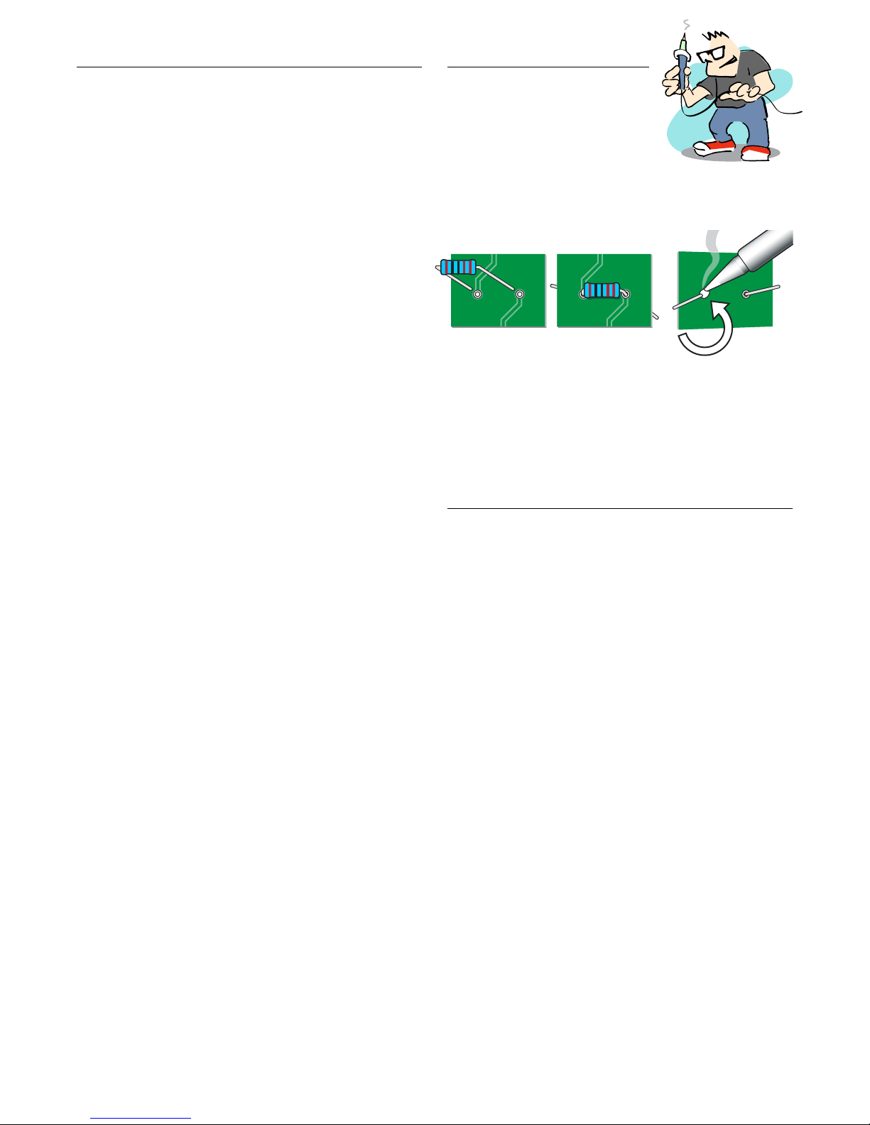
Tips for soldering
The solder joints you’ll make on the
circuit board are very small, and too
much heat can damage the board.
The idea is to make joints quickly,
without scorching the eyelets.
Hold components in place for soldering by threading the
leads through the board and bending them apart on the
reverse side.
Make your solder joints on the reverse side. Insert the tip into
the eyelet and let it heat for 4-5 seconds before touching it
with solder. This heats the contact enough for the solder to
ow nicely without damage. You don’t need much solder,
just enough to ll the eyelet. After soldering, trim away the
excess lead wire.
Give your pedal a custom paint job!
Any paint sold for use on metal will work well on the kit case.
Spray paints like Rustoleum® or Krylon® are a durable nish.
You might want to paint the case before building the kit,
so you won’t need to take the parts back out for painting.
A way to add custom graphics is to print them from your
computer onto waterslide decal paper. If you use decals,
protect them from scratches by spraying clear topcoats
over them.
Tools and supplies
Required: Soldering iron with ne point tip
Solder
Wire cutter/stripper
3/8" nut driver or socket
1/2" nut driver or socket
10mm nut driver or socket
11mm nut driver or socket
14mm wrench
#1 Phillips screwdriver
Also helpful: Clear silicone adhesive
Circuit card holder
Magnifying glass or OptiVISOR
StewMac Soldering Aids
Power: This pedal requires a standard 9V DC
center-negative power supply (not
included) and consumes less than 100mA.
There’s no battery option.
stewmac.com ©2018 StewMac page 2 of 14

Parts list
Resistor values are indicated by colored bands, read from left
to right. The rst color in the code is usually the one painted
closest to a lead wire. When a gold or silver band is present,
it’s always one of the last colors in the code. A magnier is
a big help in reading these codes.
stewmac.com ©2018 StewMac page 3 of 14
2.1mm DC power connector (1) #7468
3PDT latching footswitches (2) #1611
Metal case with 4 screws (1) #7600
Circuit board (1)
(Not pictured)
(Not pictured)
10µF capacitors (2) #7338
1/4" mono jacks, 1/4" (2) #4652
5mm LED mounting bezels (2) #7432
1µF capacitors (5) #7314
.22µF capacitor (1) #7335
.01µF capacitor (1) #7331
.022 µF capacitors (6) #7332
.1µF capacitors (5) #7334
100µF capacitors (5) #7339
100pF capacitor (1) #7326
parts: i-2203 Disaster Transport
10uF
B25KΩ linear taper pot (1) #7461
C105 reverse log pot (1) #7464
B50KΩ linear taper pot (1) #7462
B100KΩ linear taper pot (1) #7453
B5KΩ linear taper pots (2) #7452
Brown Black Black Yellow Brown
Brown Green Black Orange Brown
Brown Black Black Red Brown
Brown Black Black Black Brown
Red Red Black Brown Brown
Red Red Black Red Brown
Red Red Black Orange Brown
Yellow Purple Black Orange Brown
Yellow Purple Black Red Brown
Brown Green Black Red Brown
.001µF (1) capacitor (1) #7329
.0022µF capacitor (1) #7330
1N4148 rectier diodes (3) #7470
24" of lead wire (1) #5960
Adhesive foam tape squares (4) #7560
Control knobs (6) #7506
Brown Black Black Orange Brown
101J
100V
101J 100V
102J
100V
102J 100V
223J
100V
223J 100V
222J
100V
222J 100V
104J
100V
104J 100V
224J
100V
224J 100V
TL072CP
4558D JRC
100uF
1uF
5mm white LEDs (2) #7422
Linear voltage regulator (1) #7495
TL072CP low noise op-amp (1) #7444
JRC4558D dual high gain op-amp (1) #7446
PT2399 echo audio processor (1) #7490
PT2399
.47µF capacitor (1) #7336
474J
100V
474J 100V
PT2399
1MΩ resistor (1) #7367
47KΩ resistors (3) #7369
10KΩ resistors (11) #7362
100Ω resistors (2) #7352
2K2Ω resistor (1) #7376
22KΩ resistors (4) #7379
220KΩ resistors (3) #7381
470KΩ resistors (4) #7382
100KΩ resistor (1) #7365
15KΩ resistor (1) #7378
150KΩ resistor (1) #7373
103J
100V
103J 100V
Save time: sort the
components by type
before you art!

stewmac.com ©2018 StewMac page 4 of 14
Step 1: Install thirty-two resistors
As you get started, note that the values of each component
are printed in their proper location on the circuit board un-
less otherwise noted.
Resistors have a low prole, sitting closer to the board than
taller components, so install them rst. Their locations are
marked on the board with the value of the part.
Resistors are not polarized, so it doesn’t matter which lead
goes in which eyelet. They can be installed in either direction.
Larger resistors will need to be placed on the
board at an angle due to their size.
2K2Ω resistor (1) #7376
Red Red Black Brown Brown
470KΩ resistors (4) #7382
Yellow Purple Black Orange Brown
1MΩ resistor (1) #7367
Brown Black Black Yellow Brown
150KΩ resistor (1) #7373
Brown Green Black Orange Brown
10KΩ resistors (11) #7362
Brown Black Black Red Brown
Red Red Black Red Brown 22KΩ resistors (4) #7379
220KΩ resistors (3) #7381
Red Red Black Orange Brown
100KΩ resistor (1) #7365
Brown Black Black Orange Brown
47KΩ resistors (3) #7369
Yellow Purple Black Red Brown
Brown Green Black Red Brown 15KΩ resistor (1) #7378
100Ω resistors (2) #7352
Brown Black Black Black Brown
EarthQuaker Devices
Disaster Transport Rev2 2010
EarthQuaker Devices
Disaster Transport Rev2 2010
10K
1M 10
1
1
IJ
B5K B50K
B100K
C500K
B5K
B25K
I O G OJ L+ L+ G M F
.22
100K
47K
470K
470K
470K
.47
470K
47K
47K
10K
10K
100u
100u
100u
100u
100u
100u
10K 10K
10K
10K
10K
10K
100
100
10K
15K
150K
10K
220K
220K
2K2
22K
22K
22K
22K
.022
.022
.022
.022
.1
.1
.1
.1
.1
.01
.001
1
1
1
.001
.022
.0022 .022
220K
OJOGGIGI V+
10K
1M 10
1
1
IJ
B5K B50K
B100K
C500K
B5K
B25K
I O G OJ L+ L+ G M F
.22
100K
47K
470K
470K
470K
.47
470K
47K
47K
10K
10K
100u
100u
100u
100u
100u
100u
10K 10K
10K
10K
10K
10K
100
100
10K
15K
150K
10K
220K
220K
2K2
22K
22K
22K
22K
.022
.022
.022
.022
.1
.1
.1
.1
.1
.01
.001
1
1
1
.001
.022
.0022 .022
220K
OJOGGIGI V+

stewmac.com ©2018 StewMac page 5 of 14
Step 2: Install three diodes
Diodes are polarized, so they need to be installed in the
correct orientation.
Note the stripe around one end: this marks the negative
(minus) lead of the diode. On the circuit board, the printed
outline of the diodes also shows this stripe. Install each
diode so that its stripe matches the direction shown on the
circuit board.
EarthQuaker Devices
Disaster Transport Rev2 2010
10K
1M 10
1
1
IJ
B5K B50K
B100K
C500K
B5K
B25K
I O G OJ L+ L+ G M F
.22
100K
47K
470K
470K
470K
.47
470K
47K
47K
10K
10K
100u
100u
100u
100u
100u
100u
10K 10K
10K
10K
10K
10K
100
100
10K
15K
150K
10K
220K
220K
2K2
22K
22K
22K
22K
.022
.022
.022
.022
.1
.1
.1
.1
.1
.01
.001
1
1
1
.001
.022
.0022 .022
220K
OJOGGIGI V+
1N4148 rectier diodes (3) #7470

stewmac.com ©2018 StewMac page 6 of 14
Step 3: Install twenty-nine capacitors
The three types of capacitors shown above are polarized,
and have to be installed in the correct orientation. Note
the stripe running the length of each cap; this identies the
negative (minus) lead. On the circuit board, the circle for this
cap’s location has a round through hole on one side, and a
square through hole on the other: insert the capacitors with
their stripe facing the round hole side. (On polarized caps of
this type, there’s a second way to identify the minus lead: it
is the shorter of the two leads.)
The remaining capacitors are not polarized. Solder these
caps in place facing either direction.
IMPORTANT: Below, one 10μF capacitor should be soldered
into a spot labed “100u” on the board, and a 100pF capacitor
should be soldered into the spot labled “.001” on the board.
Be sure to follow the guide lines carefully!
EarthQuaker Devices
Disaster Transport Rev2 2010
EarthQuaker Devices
Disaster Transport Rev2 2010
10K
1M 10
1
1
IJ
B5K B50K
B100K
C500K
B5K
B25K
I O G OJ L+ L+ G M F
.22
100K
47K
470K
470K
470K
.47
470K
47K
47K
10K
10K
100u
100u
100u
100u
100u
100u
10K 10K
10K
10K
10K
10K
100
100
10K
15K
150K
10K
220K
220K
2K2
22K
22K
22K
22K
.022
.022
.022
.022
.1
.1
.1
.1
.1
.01
.001
1
1
1
.001
.022
.0022 .022
220K
OJOGGIGI V+
10K
1M 10
1
1
IJ
B5K B50K
B100K
C500K
B5K
B25K
I O G OJ L+ L+ G M F
.22
100K
47K
470K
470K
470K
.47
470K
47K
47K
10K
10K
100u
100u
100u
100u
100u
100u
10K 10K
10K
10K
10K
10K
100
100
10K
15K
150K
10K
220K
220K
2K2
22K
22K
22K
22K
.022
.022
.022
.022
.1
.1
.1
.1
.1
.01
.001
1
1
1
.001
.022
.0022 .022
220K
OJOGGIGI V+
.1μF capacitors (5) #7334
104J
100V
104J 100V
.01μF capacitor (1) #7331
103J
100V
103J 100V
.47μF capacitor (1) #7336
474J
100V
474J 100V
100μF capacitors (5) #7339
100uF
100pF capacitor (1) #7326
Solder to indicated spot marked .001
101J
100V
101J 100V
223J
100V
223J 100V
.0022μF capacitor (1) #7330
.022μF capacitors (6) #7332
222J
100V
222J 100V
1μF capacitors (5) #7314
1uF
10μF capacitors (2) #7338
Solder to indicated spot marked 100u
10uF
.001μF capacitor (1) #7329
102J
100V
102J 100V
.22μF capacitor (1) #7335
224J
100V
224J 100V

stewmac.com ©2018 StewMac page 7 of 14
Step 4: Install two op-amps, and one echo audio processor
The op-amps and echo audio processor have to be oriented correctly
in order to function properly. There are two indicators to guide you
in positioning it:
The op-amps have a dot molded into the corner of the top side. The
locations on the circuit board have a solid rectangle marked inside
the outlines for the components. The molded dot on the op-amps
need to be oriented in the same direction as the solid rectangle.
The echo audio processor has a small divot on one end. This should be
oriented with the solid rectangle in its location on the circuit board.
Step 5: Install one linear voltage regulator
The linear voltage regulator is directional, and needs to be installed
in a specic orientation. Note that it has a at side. On the circuit
board, its location outline also has a at side, install the transistor to
match this outline.
EarthQuaker Devices
Disaster Transport Rev2 2010
10K
1M 10
1
1
IJ
B5K B50K
B100K
C500K
B5K
B25K
I O G OJ L+ L+ G M F
.22
100K
47K
470K
470K
470K
.47
470K
47K
47K
10K
10K
100u
100u
100u
100u
100u
100u
10K 10K
10K
10K
10K
10K
100
100
10K
15K
150K
10K
220K
220K
2K2
22K
22K
22K
22K
.022
.022
.022
.022
.1
.1
.1
.1
.1
.01
.001
1
1
1
.001
.022
.0022 .022
220K
OJOGGIGI V+
TL072CP
4558D JRC
TL072CP low noise op-amp (1) #7444
JRC4558D dual high gain op-amp (1) #7446
PT2399 echo audio processor (1) #7490
PT2399
EarthQuaker Devices
Disaster Transport Rev2 2010
10K
1M 10
1
1
IJ
B5K B50K
B100K
C500K
B5K
B25K
I O G OJ L+ L+ G M F
.22
100K
47K
470K
470K
470K
.47
470K
47K
47K
10K
10K
100u
100u
100u
100u
100u
100u
10K 10K
10K
10K
10K
10K
100
100
10K
15K
150K
10K
220K
220K
2K2
22K
22K
22K
22K
.022
.022
.022
.022
.1
.1
.1
.1
.1
.01
.001
1
1
1
.001
.022
.0022 .022
220K
OJOGGIGI V+
Linear voltage regulator (1) #7495
stewmac.com ©2018 StewMac page 8 of 14
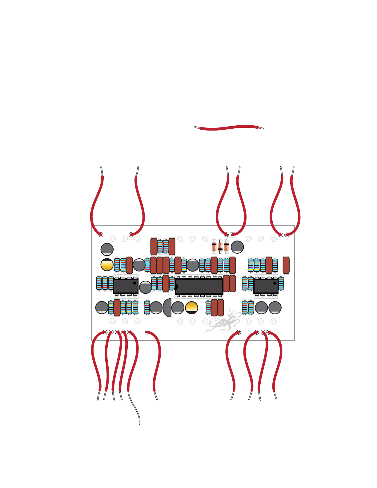
Step 6: Install sixteen lead wires
The kit comes with 24” of lead wire. Cut the wire into 1-1/4”
sections. This will give you fteen 1-1/4” sections and one
that is approximately 1-1/2” long.
Strip around 3/32” o both ends of the 1-1/4” pieces. On the
1-1/2” piece, strip 3/32” o one end and 1/4” o of the other.
This allows it to jump lugs on the footswitch.
Solder the leads onto the board. The longer lead goes into
the through hole marked OJ.
EarthQuaker Devices
Disaster Transport Rev2 2010
10K
1M 10
1
1
IJ
B5K B50K
B100K
C500K
B5K
B25K
I O G OJ L+ L+ G M F
.22
100K
47K
470K
470K
470K
.47
470K
47K
47K
10K
10K
100u
100u
100u
100u
100u
100u
10K 10K
10K
10K
10K
10K
100
100
10K
15K
150K
10K
220K
220K
2K2
22K
22K
22K
22K
.022
.022
.022
.022
.1
.1
.1
.1
.1
.01
.001
1
1
1
.001
.022
.0022 .022
220K
OJOGGIGI V+
24" of lead wire (1) #5960
stewmac.com ©2018 StewMac page 9 of 14
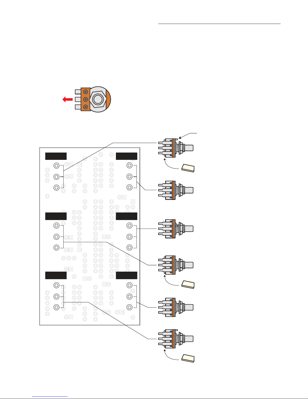
Step 7: Install six control pots
The last components to go onto the circuit board are the
six control pots. They install on the back of the board.
Each pot has three connecting lugs; with the board in the
orientation shown below, pots should be installed with their
leads facing to the left.
If any pot has an index pin protruding from the case, break
it o before installation, so the pot will mount ush against
the pedal case. Needle nose pliers work well for removing
the pins.
Use the adhesive foam tape to insulate the back of the three
pots that lay over the circuit board from the soldered leads
of the other parts. Solder the pot in place, making sure the
foam back sits at the back of the board.
Pots should be installed with
their leads facing to the left.
B100KΩ “depth” pot (1) #7453
Apply adhesive foam tape to back of this pot
C105 “rate” pot (1) #7464
Solder to indicated spot marked C500K
If the pot has an index pin, break it o.
B25KΩ “tone” pot (1) #7461
B50KΩ “time” pot (1) #7462
Apply adhesive foam tape to back of this pot
B5KΩ “mix” pot #7452
B5KΩ “repeats” pot #7452
Apply adhesive foam tape to back of this pot
B100K C500K
B50K B5K
B5K B25K

stewmac.com ©2018 StewMac page 10 of 14
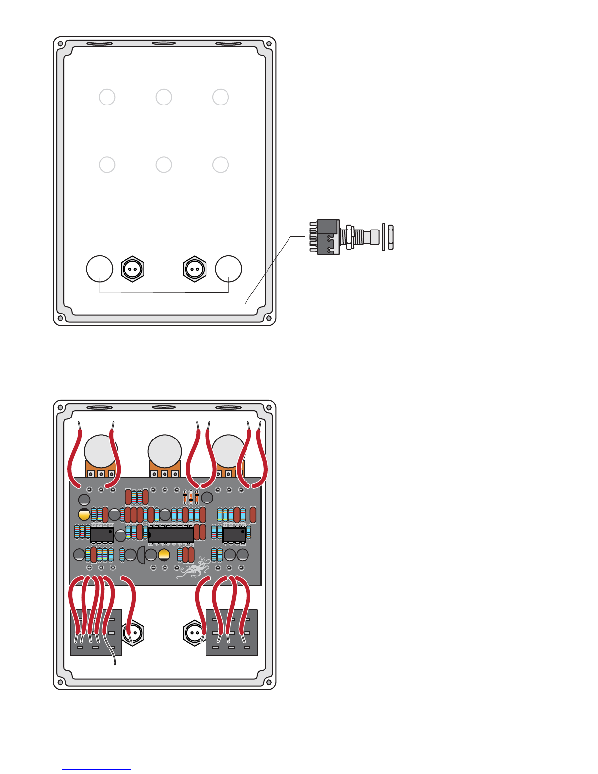
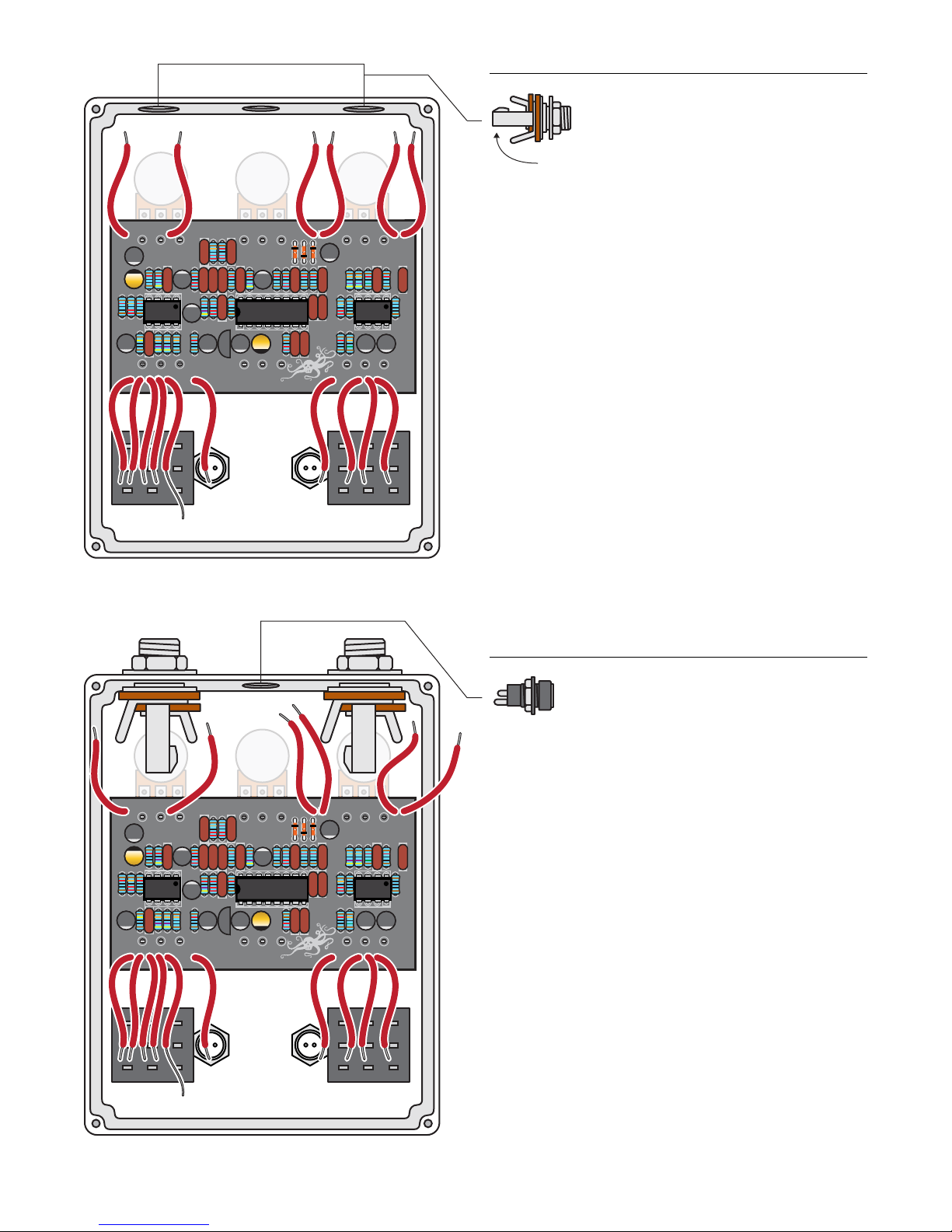
Step 8: Install two LED indicator lights
The LED mounting bezel consists of two main parts: A ring
that the LED ts into, and a plastic plug that goes over the
LED from the back side to keep it in place.
Like some of the caps and diodes, the LEDs are polarized
and have to be installed in a specic direction. One side
of the diode has a at edge, indicating the negative lead.
Another indication is that the negative lead is shorter than
the positive.
Install the mounting bezels through the front of the
enclosure. From the inside, slip a lock washer and nut on both
and tighten them up using a 3/8" socket. Insert the LEDs into
the bezel so the at side (short lead) faces the holes for the
footswitches. Feed the leads through the plastic plug, press
the plug down until it’s tight in the bezel. The LEDs will be
held in place when you solder the leads to the switches and
circuit board. For a more secure mount, you can run a bead
of clear silicone adhesive around the plastic plug.
5mm LED mounting bezels (2) #7432
5mm white LEDs (2) #7422
case
x2
5mm LED mounting bezels (2) #7432
5mm white LEDs (2) #7422
case
x2
stewmac.com ©2018 StewMac page 11 of 14
Step 9: Install two footswitches
Step 10: Install the circuit board
Install the footswitches so the part number printed on the
side faces the bottom of the enclosure. Use a 14mm wrench
to tighten them up. When looking at the back of the pedal
the switch on the left is the eect bypass switch that turns
on the pedal, the one on the right turns on the modulation
when the main eect is engaged.
The circuit board is held in place by the control pots.
Install their shafts through the top of the case, and thread
washers onto them on the outside. Using a 10mm wrench
install the mounting nuts so they are good and snug, but
take care not to overtighten.
Do not connect any of the lead wires at this point.
EarthQuaker Devices
Disaster Transport Rev2 2010
10K
1M 10
1
1
IJ
B5K B50K
B100K
C500K
B5K
B25K
I O G OJ L+ L+ G M F
.22
100K
47K
470K
470K
470K
.47
470K
47K
47K
10K
10K
100u
100u
100u
100u
100u
100u
10K 10K
10K
10K
10K
10K
100
100
10K
15K
150K
10K
220K
220K
2K2
22K
22K
22K
22K
.022
.022
.022
.022
.1
.1
.1
.1
.1
.01
.001
1
1
1
.001
.022
.0022 .022
220K
OJOGGIGI V+
3PDT latching footswitches (2) #1611
stewmac.com ©2018 StewMac page 12 of 14
Step 11: Install two jacks
Step 12: Install one DC jack
The input and output jacks are a tight t in this enclosure
and need to oriented in a specic way in order for the lugs
to clear the control pots. Install the jacks with the positive
lug facing up at you. A 1/2" wrench is recommended.
Install the DC jack using a 11mm wrench.
EarthQuaker Devices
Disaster Transport Rev2 2010
10K
1M 10
1
1
IJ
B5K B50K
B100K
C500K
B5K
B25K
I O G OJ L+ L+ G M F
.22
100K
47K
470K
470K
470K
.47
470K
47K
47K
10K
10K
100u
100u
100u
100u
100u
100u
10K 10K
10K
10K
10K
10K
100
100
10K
15K
150K
10K
220K
220K
2K2
22K
22K
22K
22K
.022
.022
.022
.022
.1
.1
.1
.1
.1
.01
.001
1
1
1
.001
.022
.0022 .022
220K
OJOGGIGI V+
1/4" mono jacks, 1/4" (2) #4652
Positive lug facing upward
EarthQuaker Devices
Disaster Transport Rev2 2010
10K
1M 10
1
1
IJ
B5K B50K
B100K
C500K
B5K
B25K
I O G OJ L+ L+ G M F
.22
100K
47K
470K
470K
470K
.47
470K
47K
47K
10K
10K
100u
100u
100u
100u
100u
100u
10K 10K
10K
10K
10K
10K
100
100
10K
15K
150K
10K
220K
220K
2K2
22K
22K
22K
22K
.022
.022
.022
.022
.1
.1
.1
.1
.1
.01
.001
1
1
1
.001
.022
.0022 .022
220K
OJOGGIGI V+
2.1mm DC power connector (1) #7468
stewmac.com ©2018 StewMac page 13 of 14
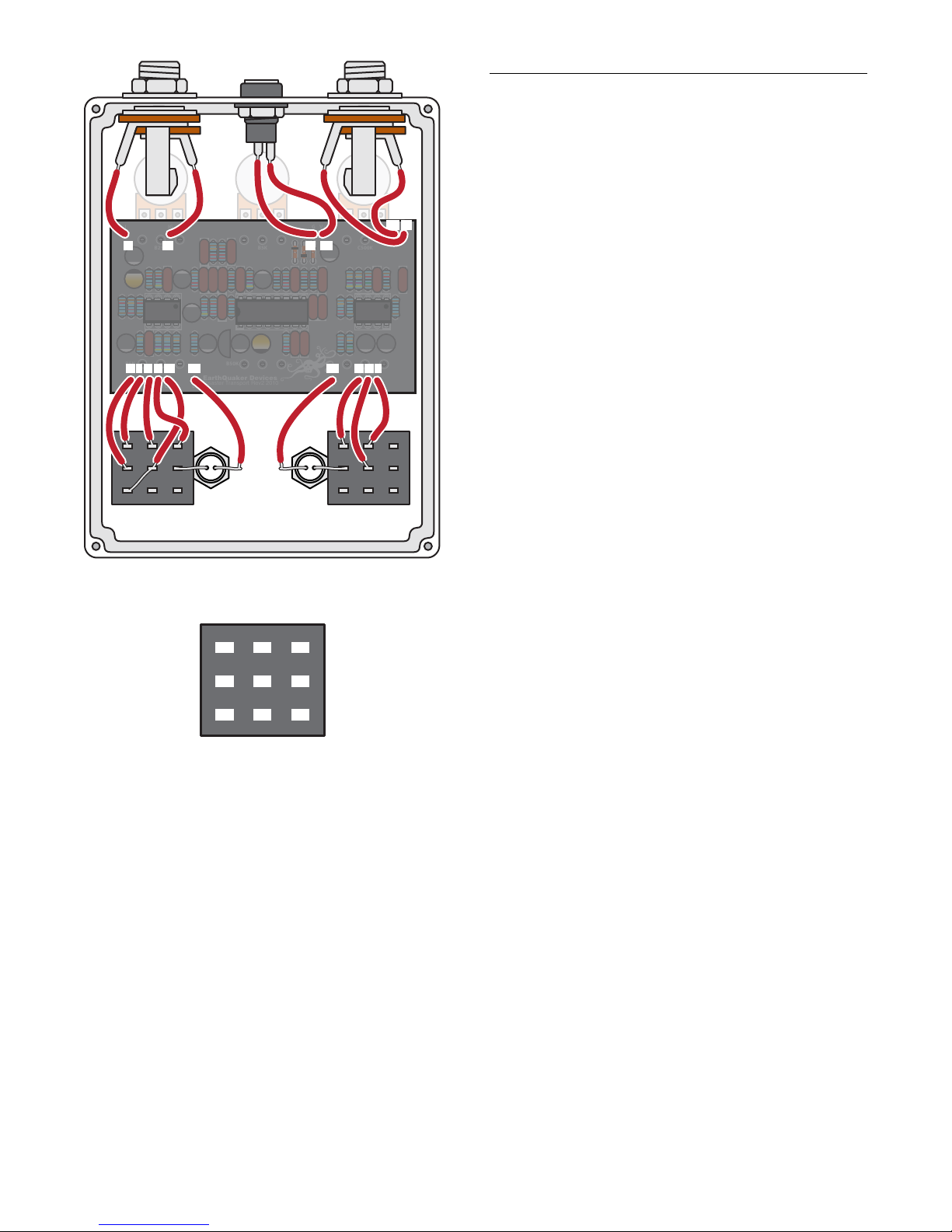
Step 13: Final wire-up
With all of the components in place, it is time to wire it all up.
Starting at the left hand top of the circuit board and working
to the right, take the lead wire labeled I and solder it to the
tip lug of the input jack. To identify, look for the lug that is
attached to the spring metal piece that attaches to the tip
of the guitar cord when it is plugged in.
Solder the next lead, labeled IG, to the sleeve lug on the
jack. This is the lug that is attached to the threaded shaft
of the jack.
Next, solder the lead labeled G to the center tip (short) lug
of the DC jack. Then solder the lead labeled V+ to the sleeve
(long) lug.
Continuing work to the right take lead labeled OG and solder
it to the sleeve of the output jack. The solder the lead labeled
OJ to the tip lug.
Working from the bottom left hand side of the circuit board
and soldering to the bypass switch, solder the lead labeled
IJ to lug #2. Solder the I lead to lug #1. Solder the O lead to
lug #4. Solder the G lead to lug #7. Solder the OJ lead to lug
#5 jumping to lug #3.
Continuing to work to the right, solder the L+ lead to the
positive (long) lead of the bypass LED. Solder the negative
(short) lead to lug #8 on the switch.
Moving on to the modulate switch, solder the L+ to the
positive (long) lead of LED. Solder the negative (short) lead
to lug #2 on the switch.
Solder the G lead to lug #1 on the switch. Solder the M lead
to lug #5, and the F lead to lug #4.
Screw on the back panel and plug in!
The lugs on the footswitches are
numbered as shown above.
EarthQuaker Devices
Disaster Transport Rev2 2010
10K
1M 10
1
1
IJ
B5K B50K
B100K
C500K
B5K
B25K
I O G OJ L+ L+ G M F
.22
100K
47K
470K
470K
470K
.47
470K
47K
47K
10K
10K
100u
100u
100u
100u
100u
100u
10K 10K
10K
10K
10K
10K
100
100
10K
15K
150K
10K
220K
220K
2K2
22K
22K
22K
22K
.022
.022
.022
.022
.1
.1
.1
.1
.1
.01
.001
1
1
1
.001
.022
.0022 .022
220K
OJOGGIGI V+
IJ L+ L+
IG G V+
OG OJ
I O G OJ G M F
I
1
2
3
4
5
6
7
8
9
stewmac.com ©2018 StewMac page 14 of 14
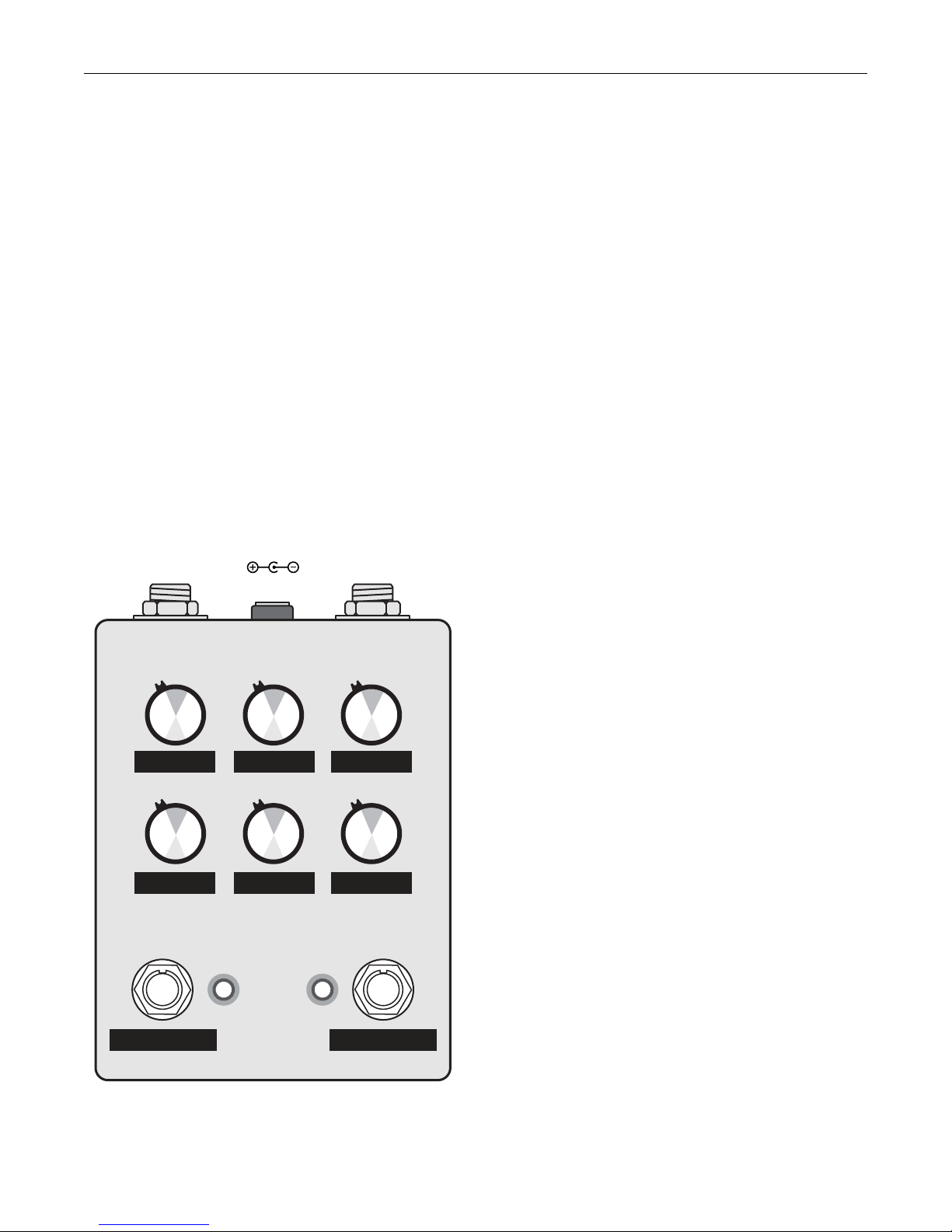
Here’s how the controls work:
Mix:Sets the output level of the eected signal. This should
be treated as a gain control/ master volume for the delay
line. Unity is around noon and everything above noon will
boost the delayed signal louder than the original. This is a
gain control so, like any pedal with a lot of gain, a hint of
noise and distortion at max setting is completely normal.
Tone:Most delay pedals are heavily ltered at the output
to remove the clock noise and other unwanted hash that
is common from extending the range of the delay time
beyond the limit of the circuitry. This usually leaves the delay
sounding dark and muddy, and disappears when hitting it
with dirt. The Disaster Transport has done away with a lot
of the heavy ltering and replaced it with a tone control
which allows the user to choose their desired sound and
results in more natural tape-like repeats. The tone control
is at its darkest fully counterclockwise and brightens as you
turn it clockwise. A good rule of thumb is to leave the tone
control between o (fully counterclockwise) and noon at
longer delay times. This will remove all the common noise
from hyperextending the circuit.
Time:From about 30ms fully counterclockwise to about
625ms fully clockwise.
Repeats:Sets the regeneration of the delay line. From one
single repeat fully counterclockwise, subtle repeats around
9 o’clock, strong naturally decaying repeats at noon, near
innite repeats around 2 o’clock and full on self oscillation
fully clockwise.
Depth:Sets the depth of the modulation to the delay line.
The modulation is true pitch-shifting vibrato, higher depth
settings will give sea sick pitch bending, lower settings
will yield a more natural chorus/leslie/tremolo setting
depending on modulation rate and delay time. To achieve
a more natural modulation, the depth should be reduced as
the delay time is increased.
Rate:Sets the speed of the modulation. Goes from painfully
slow to way-to-fast allowing several dierent modulation
styles to reveal themselves.
Bypass:Turns the eect on/o.
Modulate:When activated, it emulates the decaying sound
of a tape delay. This makes the Rate and Depth knobs aect
that modulation as well. When the switch is turned o, the
other four knobs are the only ones that aect the signal, and
the delay sounds will repeat without decaying.
Power:Use a standard 9 volt DC power supply with a
2.1mm negative-center barrel (not included). We always
recommend pedal-specic, transformer-isolated wall-wart
power supplies or supplies with separate isolated outputs.
Pedals will make extra noise if there is ripple or unclean
power. Switching-type power supplies, daisy chains and
non-pedal specic power supplies do not lter dirty power as
well and let through unwanted noise.Do not run at higher
voltages! Current draw is 35 mA.
INPUTOUTPUT
9V DC
REPEATSRATE TONE
TIMEDEPTH
MODULATE BYPASS
MIX
Other StewMac Music Pedal manuals

StewMac
StewMac SCREAMER Manual

StewMac
StewMac TWO KINGS BOOST DOUBLE-POWERED ROYAL TONE Manual

StewMac
StewMac INTERVAL FUZZ Manual

StewMac
StewMac EC EXPANDER PEDAL KIT Manual

StewMac
StewMac MXR PHASE 90 User manual

StewMac
StewMac FAN TREMOLO Manual

StewMac
StewMac NYC BIG MUFF PI User manual

StewMac
StewMac LIGHTCYCLE PHASOR II Manual

StewMac
StewMac SWELL DRIVE Manual

StewMac
StewMac SUN FUZZ Manual


