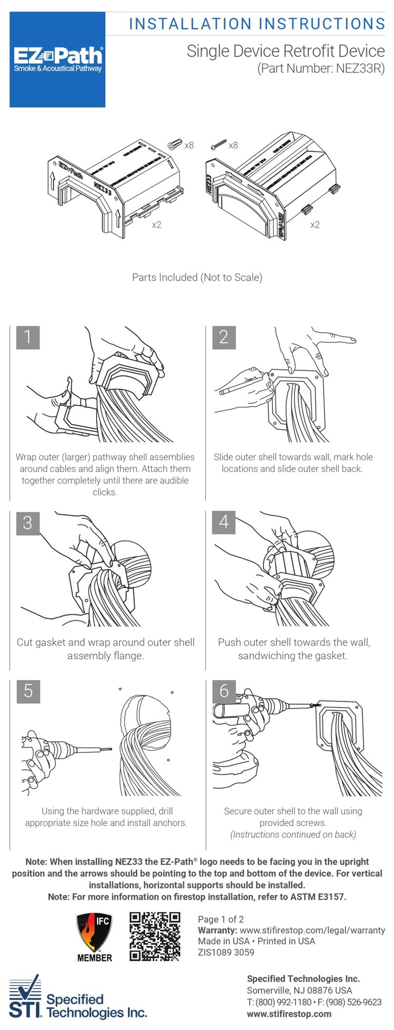
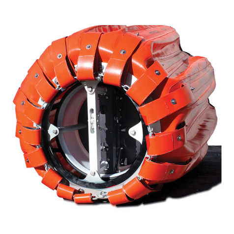
STI EZ-Path 44+ Series User manual
Other STI Firefighting Equipment manuals
Popular Firefighting Equipment manuals by other brands
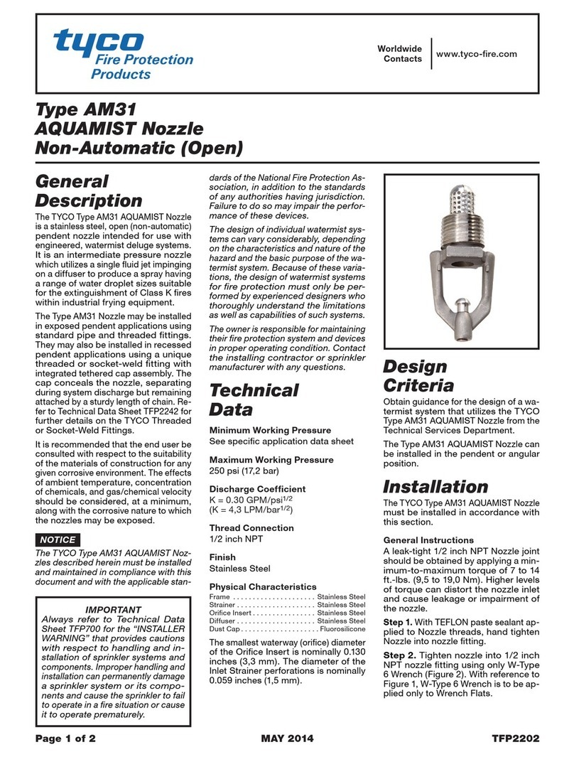
Tyco Fire Protection Products
Tyco Fire Protection Products AM31 AQUAMIST Nozzle instructions
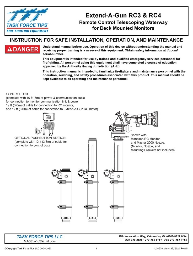
Task Force Tips
Task Force Tips Extend-A-Gun RC3 INSTRUCTION FOR SAFE INSTALLATION, OPERATION, AND MAINTENANCE
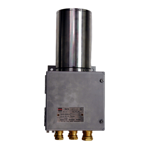
Autronica
Autronica AutroSafe BSD-321/EX manual

POK
POK Froggy user manual

Waterous
Waterous AQUIS Series Installation, operation and maintenance instructions
CTP
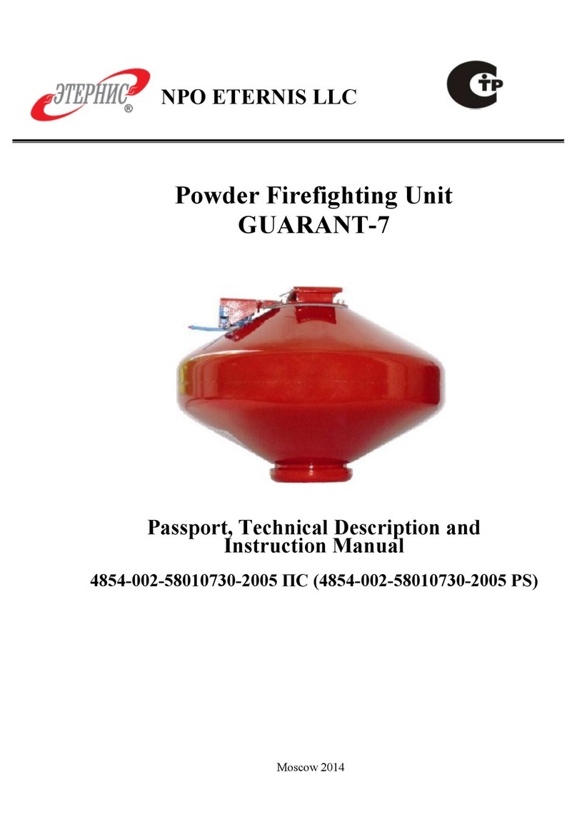
CTP NPO ETERNIS GUARANT-7 Technical description and instruction manual
