8
Insert the core bricks (g. L and M)
The core bricks are delivered packed sepa-
rately.
Core bricks with slight transportation dam-
age may still be used. This does not impair
the function of the heater.
The heating elements (17) must be lifted
slightly to insert the core bricks (9) (g. L).
Place the rst core brick with the heating el-
ement recess at the top some distance away
from the right thermal insulation under the
heater and push to the right and rear ther-
mal insulation. The elongated holes form
the heating channels.
When lifting the heating elements, make
sure that the through holes in the side
thermal insulation are not damaged by the
heating elements.
Then reinsert the cover plate (10) on top of
the core bricks (g. N).
2.5.2 Electrical Connection
The heating elements are connected electri-
cally to mains terminals“L”,“N”and “ ”with
1/N/PE ~ 50 Hz 220 V.
Direct connection with NYM cable is possi-
ble. Use at least 3x2.5mm² for the mains
connection and 2x1.5mm² to the external
temperature controller. Observe the appro-
priate circuit diagrams for this.
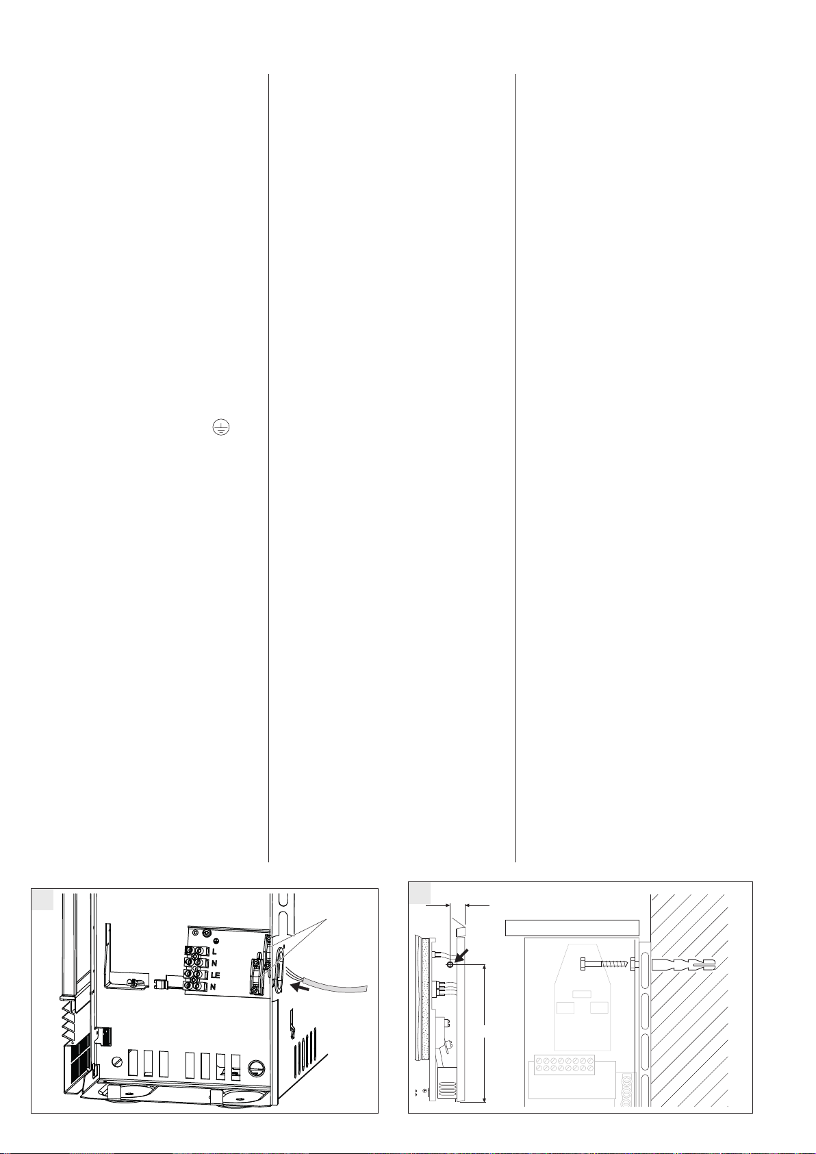
Connection
Add ferrules to all wires before connection.
Relieve the strain on the electrical connec-
ting leads as required and connect accor-
ding to the electrical circuit diagram in the
device (on the inside of the right side panel)
or the connection diagram.
Unit rating plate
Observe the labeling on the rating plate and
the circuit diagram!
2.5.3 Readying unit for operation
Cleaning the unit (g. O and P)
The open unit must be cleaned after instal-
lation and insertion of the core bricks. The
fans and the air guidance assembly must be
removed for this.
Unscrew and remove the air guidance
assembly (16)
Lift and remove the fan (18) after loos-
ening (not removing) the screws at the
front of the support brackets (pay atten-
tion to cable laying!).
Make sure the wires are not damaged
when setting down the removed parts.
Clean the oor plate and fan (avoid
damage to lamellas!). Then re-install the
fans, possibly the temperature limiter
and the air guidance module (correct
cable laying!).
Close the unit (g. Q and R)
Hang in the inside front wall with ther-
mal insulation swung forward slightly at
an angle at the top edge and screw at
the bottom edge with 2 screws;
Hang in the right side wall at the bot-
tom, tilt up, hang in at top and x with
screws (b1 and b2); (reverse order see
2.5.1 – disassembly right side wall g. G -
J);
Hang in front wall at top, swing to the
heater at the bottom and x with 2
screws
(always use the two inside threaded
holes) (g. Q);
Tighten the air inlet grille (5) with both
the quarter-turn caps (g. R);
Hang the top edge of the air inlet grille
in the lock screws at the air guidance as-
sembly and then press the bottom over
the catch springs (g. R).
2.6 First-time Operation
2.6.1 Function Test
Check the function of the fan for the storage
unit by switching on the room temperature
regulator.
2.6.2 Charging
The units can be started without initial
heating up after the function test. Charging
takes place by adjusting the mechanical
charging control.
During initial charging, the charging in kWh
must be determined and compared with the
maximum permissible charging from the
cold state specied in the "Technical Data".
The determined charging may not exceed
the maximum permissible charging from
the cold state.
During initial charging, a smell may be pro-
duced, the room should therefore be ade-
quately aired (1.5 times air change, e.g. tilted
windows). Initial charging in the bedroom
should not take place while sleeping in it.
2.7 Repair, Conversion
of the unit
For the initial installation and for re-instal-
lation of a unit which has been dismantled
for repairs or which was in operation some-
where else, proceed according to these
installation instructions.
In these cases the following must be paid
special attention to: Parts of the thermal
insulation which show visible signs of dam-
age, or changes which could impair safety,
must be replaced by new parts. The insula-
tion must be tested and the rated consump-
tion measured before commissioning.
26_07_27_0265
60
464
T
S15
D0000045940