STIEBEL ELTRON SBB 300 Trend User manual
Other STIEBEL ELTRON Water Heater manuals
STIEBEL ELTRON
STIEBEL ELTRON DEL 18 Plus Instruction Manual

STIEBEL ELTRON
STIEBEL ELTRON SHU 5 SLi comfort User manual
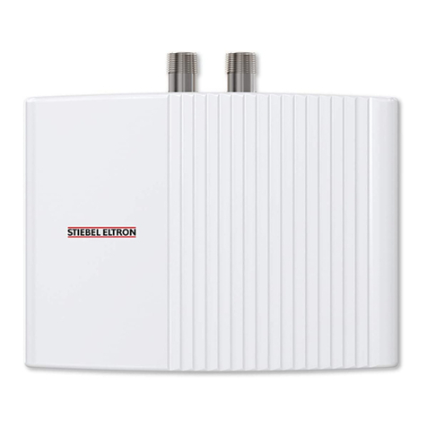
STIEBEL ELTRON
STIEBEL ELTRON EIL 3 Premium Instruction Manual
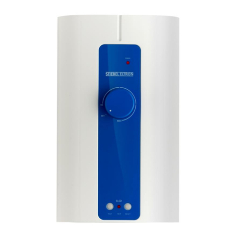
STIEBEL ELTRON
STIEBEL ELTRON IS E User manual

STIEBEL ELTRON
STIEBEL ELTRON PER 18/21/24 Instruction Manual

STIEBEL ELTRON
STIEBEL ELTRON SBS 800 W Instruction Manual

STIEBEL ELTRON
STIEBEL ELTRON PSH 30 Si Instruction Manual

STIEBEL ELTRON
STIEBEL ELTRON DS 35 EC User manual
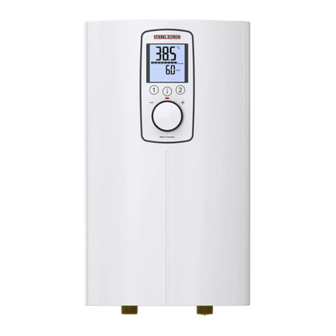
STIEBEL ELTRON
STIEBEL ELTRON DCE-X 6/8 Premium Instruction Manual
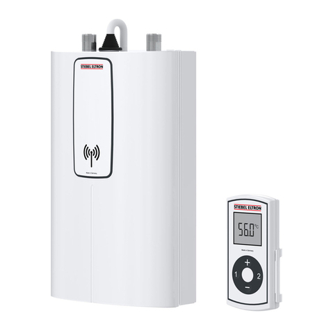
STIEBEL ELTRON
STIEBEL ELTRON DCE 11/13 Specification sheet
STIEBEL ELTRON
STIEBEL ELTRON IS 35 E User manual
STIEBEL ELTRON
STIEBEL ELTRON ESH 10 U-P Plus Instruction Manual
STIEBEL ELTRON
STIEBEL ELTRON SHC 10 Instruction Manual
STIEBEL ELTRON
STIEBEL ELTRON SimpleX User manual
STIEBEL ELTRON
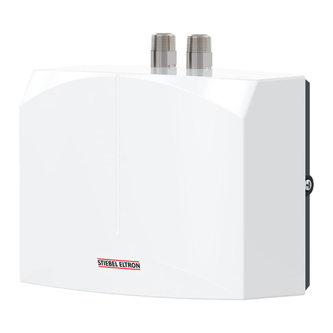
STIEBEL ELTRON EBK 5 K Quick start guide
STIEBEL ELTRON
STIEBEL ELTRON DHM 3 User manual
STIEBEL ELTRON
STIEBEL ELTRON DHF 13 C User manual

STIEBEL ELTRON
STIEBEL ELTRON SNO 5 Plus GB Specification sheet
STIEBEL ELTRON
STIEBEL ELTRON DHX 15 Select User manual

STIEBEL ELTRON
STIEBEL ELTRON SHU 10 SLi comfort Instruction Manual
Popular Water Heater manuals by other brands

Kenmore
Kenmore 153.582400 Use & care guide

clage
clage E-Mini Series Operating and installation instructions

Toyotomi
Toyotomi Oil Miser OM-180 installation manual

Bradford White
Bradford White EF Series Service manual

Eccotemp
Eccotemp 40-H Use & care manual

Dimplex
Dimplex ECSd125-580 Installation and user instructions

Dux
Dux 32FCR6N installation manual

Noritz
Noritz N-132M Owner's guide and installation manual

TESY
TESY GCV7/4S 10047 Instructions for use and maintenance

A.O. Smith
A.O. Smith Gphe 50 instruction manual

Toyotomi
Toyotomi Oil Miser OM-148 (Type D) Operation and maintenance instructions

Koryo
Koryo KWHZF15Y user manual

Pentair
Pentair PSC-14-4-02 Installation and operation manual

GE
GE 40M06AAG Energy guide

Thermor
Thermor AEROMAX SPLIT 2 Instructions for use

American Hometec
American Hometec AHQ-B03X Installation and operation manual

PVI
PVI MAXIM Specifications

Sunerg Solar Energy
Sunerg Solar Energy Calor Top 200D Installation & owner's manual
