Stienen B.E. PL-9000 User manual

1
USER MANUAL
FOR THE
PL-9000(-i) POULTRY COMPUTER
V 01.48.0
PL-9000(-i)

Shut down power before opening the poultry computer!
This poultry computer contains exposed live parts!
Only to be opened by authorized personnel!
WARNING
Although utmost care has been given to the quality of this equipment during the design and manufacturing stages,
technical malfunctions can never be ruled out. The user should provide for an adequate alarm system and/or
emergency provisions to prevent a technical failure of the equipment and peripheral facilities leading to danger to
persons, animals or property.
NOTE DOWN THE FOLLOWING IN CASE OF AN EMERGENCY
Possible causes
Circumstances in which the emergency occurred
Date and software version number
Installer settings
Please contact our Customer Service Department, if you have any questions. Be sure to have all necessary data at
hand. To ensure a speedy solution to the malfunction and to avoid any misunderstandings, it is advisable to note
down the cause and the circumstances in which the malfunction occurred before contacting us
(www.stienenbe.com).
No part of this document may be reproduced or transmitted in any form or by any means, electronic or
mechanical, for any purpose, without the express written permission of Stienen B.E.
Stienen B.E. accepts no liability for the contents of this manual and explicitly waives all implicit guarantees of
merchantability or fitness for a certain use. Stienen B.E. also reserves the right to improve or change this manual
without being under the obligation to inform any person or organization of any such improvement or change.
Stienen B.E. cannot be held liable for any damage, loss or injury resulting from improper use or from use not in
accordance with the instructions in this manual.
©Copyright Stienen B.E.

Contents Page
INTRODUCTION...................................................................................................................1
Ventilation groups..............................................................................................................1
Heating controls ................................................................................................................2
Cooling ............................................................................................................................2
Humidification ...................................................................................................................2
Timers .............................................................................................................................2
Counters ..........................................................................................................................2
Window............................................................................................................................3
Keyboard..........................................................................................................................3
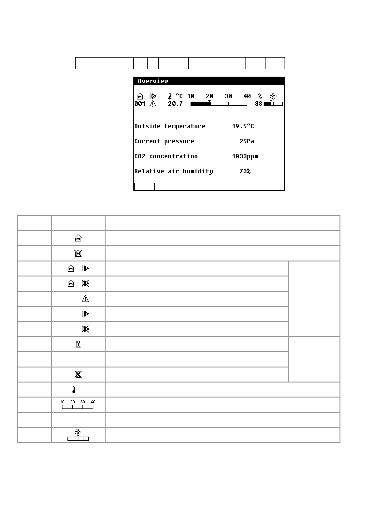
OVERVIEW ..........................................................................................................................6
MAIN MENU.........................................................................................................................7
CLIMATE CONTROLS............................................................................................................7
House temperature ............................................................................................................7
Relative or absolute temperature setting...............................................................................8
Ventilation groups..............................................................................................................8
Heatings.........................................................................................................................13
Cooling ..........................................................................................................................14
Miscellaneous controls ...................................................................................................... 14
Compensations climate control ..........................................................................................15
Growth curves.................................................................................................................21
Temperature overview...................................................................................................... 22
Alarm ............................................................................................................................22
House status...................................................................................................................24
SILOS................................................................................................................................25
Silo contents...................................................................................................................25
Silo status ......................................................................................................................25
Fillet ..............................................................................................................................25
COUNTERS.........................................................................................................................26
Clear all counters.............................................................................................................27
Alarm ............................................................................................................................27
TIMERS .............................................................................................................................28
Dosage timers.................................................................................................................28
Light timers ....................................................................................................................29
Week programme ............................................................................................................30
Overview........................................................................................................................30
Dosage curves ................................................................................................................31
Date / Time ....................................................................................................................31
Overview timers ..............................................................................................................31
Alarm ............................................................................................................................31
INFO..................................................................................................................................32
Animal data ....................................................................................................................32
ALARM...............................................................................................................................34
Alarm codes....................................................................................................................34
SYSTEM .............................................................................................................................36
Fahrenheit ......................................................................................................................36
Display...........................................................................................................................36
MAINTENANCE AND CHECK UP..........................................................................................37

CLEANING HR SENSOR, CO2SENSOR OR MEASURING FAN
WITH A HIGH-PRESSURE SPAY GUN IS NOT ALLOWED
Remove the HR sensor and CO2 sensor from the room and store it
somewhere safe before cleaning the room. Also screw the protection cap
onto the plug of the extension cable to prevent water from penetrating into
the plug. When connecting the sensor via a fixed socket outlet (FSO), push
on the flap of the fixed socket outlet until you hear it click (lock).

1
INTRODUCTION
Modern poultry farming requires an optimum climate in the houses to achieve good operating results. As a rule,
this is achieved by using a mechanical ventilation system. Important in this respect is the air supply to the
animals and the creation of proper air circulation. The air distribution in the house is strongly influenced by the
type of air supply system. Effective ventilation controls, as are integrated in the PL-9000 poultry computer, can
achieve a good air quality at animal level with a low ventilation flow rate. It speaks for itself that good climate
control contributes to the animals' well-being.
The PL-9000 poultry computer enables you to fulfil virtually all your climate control wishes. The poultry
computer has practically all possible ventilation controls which are featured in modern poultry farming. The
poultry computer controls the climate in the house in such a way that the correction ratio between temperature
and ventilation is always guaranteed. To ensure that the climate in the house develops along with the growth of
your animals, the poultry computer has growth curves. By taking the influence of the weather into account, the
climate in the house can be corrected depending on the weather conditions.
In the event of a power failure, excessive temperature variation or excessive ventilation variation, the alarm will
be activated.
Since every situation is different, in daily practice only the control functions applicable to your specific situation
will be activated. This makes the operation of the poultry computer very easy and transparent.
VENTILATION GROUPS
The PL-9000 poultry computer has a maximum of 3 ventilation groups divided into:
1x main ventilation group
2x additional ventilation groups
Every ventilation group can be subdivided into a maximum of 2 ventilation controls. All ventilation controls in a
group make use of the same settings, i.e. settings per ventilation group, but have their own separate inputs and
outputs and are controlled individually.
Main ventilation group
The 1st ventilation control in this group is the main ventilation; this serves as the reference for house
temperature and pressure control compensation. The 2nd and 3rd ventilation controls in this group are only
switched on in support of the first control and they both have their own adjustable initial percentages. All
ventilation controls have an adjustable ventilation capacity (m3/h) which is combined to form the total
ventilation capacity of the main ventilation group.

2
HEATING CONTROLS
Maximum 2 independent ventilation controls can be installed.
Heating controls
On/off switching heating (relay)
Proportional: 0-10V (eventual in combination with a relay output)
COOLING
Maximum 1 independent cooling can be installed. If an RH sensor is used, the cooling can be switched off when
the relative humidity has become too high.
Cooling controls
On/off switching cooling (relay)
Time proportional control (relay)
Proportional (0-10V)
HUMIDIFICATION
Maximum 1 independent humidification control can be installed. Since cooling and humidification complement
each other, cooling can be connected to the same relay output as humidification.
TIMERS
Maximum 6 timers can be installed. A timer can be combined with a counter input to dose water, feed etc.,
using the timer. Maximum 3 timers, for dosage (feed/water) and/or for light control, can be installed. If the
timer is assigned to a 0-10V input, it can be used to create a light control (maximum 1 light control).
COUNTERS
Maximum 2 counters can be installed. The first 6 counter inputs may be combined with a timer for dosing.
I/O MODULES AND FN DEVICES
I/O module:You can use I/O modules to extend the number of outputs of the PL-9000 poultry computer, via
the ST bus (module bus). The control computer indicates which output must be driven by the PL-9000 poultry
computer.
The poultry computer has a memory chip where all settings are saved into, to ensure that the settings are
retained even when the voltage is lost.
Counter positions, burning hours, current day number in the curve etc. are not stored in the memory chip.
These values may be lost if the power supply to the poultry computer has been down for a couple of days. You
may then have to set the day number etc. again.

3
WINDOW
When the symbol is shown in the title bar and you press function key F3, the settings are displayed
graphically with the dot (●) showing the calculated value. Press F3 again to switch off the graphic display.
Whenever a key is pressed, the display will be lit for a couple of seconds so that you can also see the settings
and measurements in a dark animal house.
Scroll-window
If a window contains more lines than the screen can display, the title bar will show the symbol. This symbol
indicates that you can call up the remaining settings and/or measurements using the up and down cursor keys
( ).
KEYBOARD
Caution!
2
3
1
Only press the keys with the tip of
your finger. Sharp objects such as a
pen, pencil or screwdriver may
damage the keys!
The keyboard can be divided into four basic groups:
1. Numerical keys
2. Function keys
3. Navigation keys
The calculated setting may
differ from the value set by the
user, due to the growth curve
and/or compensations.
Screen number
Title bar
Column with settings and/or measurements
Column with calculated and/or
corrected settings
Graphic (function key F3)
Time & Date
You can use the key to select the
previous control number.
You can use the key to
select the next control
number.

4
1 Numerical keys (0..9)
The numerical keys can be used to enter a screen
number, a value or text. You can select menu choice
10 by pressing key 0.
Entering text
Numerical keys 2..9 can be used to change the name of
a control group (left and right), a timer or a counter.
The maximum text length is 15 characters (including
spaces). The character you enter is shown in a little
box. Press the numerical key repeatedly until the
required character is shown. You can enter a
punctuation mark by repeatedly pressing numerical key
1 until the required punctuation mark is shown. You
can enter a space using the 0 key.
Press once for a, twice for b etc. You can move the cursor with the and keys.
Where relevant, e.g. for menu options etc., the text will automatically start with an initial capital.
Add/remove breakpoint or period
Press the [Enter] key (edit mode)
Press and hold the [F1] function key and then press the:
[+] key to add a breakpoint/period (provided that the maximum value for periods/breakpoints has not been
reached)
[-] key to remove a breakpoint/period (provided that there is at least one period/breakpoint)
The number of breakpoints/periods is adjusted automatically.
2 Function keys (graphic, alarm, previous / next control etc.)
Function key F1 (change language)
Changing language: Hold down F1 and press on the left or right cursor key.
Function key F2 (change house status)
Use this function key to call up the house status.
Function key F3 (graphic)
Use this function key to place a graph on a window. The “graph” function is active when the LED in the
function key lights. You can switch off the “graph” function by pressing the function key again (the LED
in the key is off then).
The values in a graph are linked to the window on the basis of which the graph was drawn up. The graph is
updated automatically when you change the details in the window.
If the details in the window are displayed in graph form, the symbol will be displayed in the top right corner
of the menu line.
Select previous / next control
Select previous / next control.
If controls of the same type, e.g. ventilation groups (left, right, recirculation etc.), are
available, you can use these keys to select the previous or next control.
def3éèêë
abc2äàâçæå
mno6ñôöœø
jkl5
w
xyz9
tuv8û
.,1'-:+
ghi4îï
pqrs7
_
0

5
Alarm key
Hot key for alarm screen. The LED in the alarm key lights if there is an alarm on one of the controls.
Here you can switch the main alarm on and off. When the main alarm is off, the LED in the alarm key will flash
to indicate that the main alarm is off. No alarm is generated anymore.
Test (alarm test)
Test “yes”: This enables you to test the operation of
the alarm relay (siren). If you enter "yes" in the line
Test, the alarm relay (siren) will be switched on for
10 seconds.
You can clear the alarm test time by setting "no" in
the line Test.
(alarm temporary off)
Off “yes”: This enables you to temporarily switch off
the alarm (siren). This does not apply to the hardware
alarms which cannot be switched off temporarily. The
main alarm is switched off for 30 minutes (the lamp
will blink irregularly). The main alarm is switched on
automatically again after 30 minutes. The alarm relay
will then de-energize again, causing an alarm, if the
cause of the alarm has not been removed.
You can clear the temporary alarm deactivation time
by setting "no" in the line .
If no access code has been installed or if you have already entered the correct access code, you can switch off
the main alarm.
Attention: NEVER FORGET TO SWITCH THE ALARM BACK "ON" when you have switched this feature off
'temporarily', e.g. to solve a problem. Failing to switch it back on may have adverse effects for
humans, animals, equipment or property.
Preferably use the (alarm retard) function to solve a problem.
3 Navigation keys (menu, cursor, mode)
(Cancel)
This key cancels changes or menu option selections.
Press and hold this key to select the main menu.
(Move cursor)
Move cursor
Holding down: move cursor to first/last setting on the screen.
Move cursor or change value
(Confirm)
Menu option selection
Start change
Confirm change
The cursor is displayed as a black rectangle, e.g. .
While a change is being made, the cursor is displayed as a black border, e.g. .

6
OVERVIEW
Column number 1 2
3
4 5 6 7
Column
number Symbol Description
1 Column with house numbers (user number)
2 House not in use
2 Status main alarm (alarm relay de-energized)
2 Main alarm is switch off
2 001 Alarm in house (alarm delay time is not yet elapse)
2 001 Alarm in house (alarm delay time is elapse)
2 001 Main alarm is switch off
Alarm
3 Heat request in house
3 No heating installed
3 All heatings are switch off by user
Heating
4 °C Current house- and/or outside temperature in ºC
5 Graphic bar current house temperature
6 % Current main ventilation value in %
7 Graphic bar current main ventilation

7
MAIN MENU
If you use access codes, it is advisable to write the
code down and store it somewhere safe. If you forget
the access code, you can no longer change any
settings. As soon as one access code is active, you
can only change the setting by entering the correct
access code. The access code remains active until
you select the “Overview” window. After selecting this
window you will have to enter the access code again
to be able to change a setting.
Access code
You can use an access code to protect your computer against unauthorized access. If you want to prevent non-
authorized users from changing settings on your poultry computer, you can have an access code set.
An access code consists of a combination of 4 figures. You can have an maximum of 2 access codes set by your
installer.
CLIMATE CONTROLS
House status
You can put the house in use or out of use, using
the house status.
In use The poultry computer carries out its
control operation in accordance with
the settings.
Not in use All control, alarm and temperature
monitoring functions are switched off
(all flaps are closed, all timers are
switched off).
Use the left / right cursor keys ( ) to change
the house status.
HOUSE TEMPERATURE
The temperature, on the basis of which the ventilation controls, is also referred to as the house temperature.
The required house temperature depends on several factors. For example, young animals require a much higher
ambient temperature than older animals.
If the cursor is placed on and you push the confirmation key the curve for the
settings concerned will be displayed. You may change the curve settings or switch off the curve. Press the
cancel key to return to the previous window. If you have switched off the curve, the text 'growth curve' will be
replaced by the standard text and you can no longer access the relevant curve settings from this window (the
curve is off).

8
RELATIVE OR ABSOLUTE TEMPERATURE SETTING
Control Relative setting Absolute setting
Main ventilation group Always relative to temperature in
the house
n.a.
Ventilation groups Always relative to temperature in
the house
n.a.
Heating 1..2 If the setting is between -9.9°C and
+9.9°C, the setting is relative to the
house temperature
If a value equal to or higher than
10.0ºC is set, this will be an absolute
temperature setting.
Cooling If the setting is between -9.9°C and
+9.9°C, the setting is relative to the
house temperature.
If a value equal to or higher than
10.0ºC is set, this will be an absolute
temperature setting.
Temperature 1 and 2 You can indicate to your installer whether you want temperature control 1
and/or temperature control 2 to use relative or absolute temperature
settings.
Relative : The temperature control works with a differential temperature compared to the preset house
temperature. The temperature control is based on the preset house temperature. E.g. if you set a
differential temperature of 5.0ºC and the preset house temperature is 20.0ºC, the temperature
control will work as follows: 20.0ºC+5.0ºC = 25.0ºC. If you now change the house temperature to
18.0ºC, the temperature control will change the temperature as follows: 18.0ºC+5.0ºC = 23.0ºC.
Absolute : The temperature control works with absolute temperature settings. E.g. if you set the temperature
to 5.0ºC, the output control operation will also be based on 5.0ºC. The temperature control works
independently of the preset house temperature.
VENTILATION GROUPS
The number of menu options in the “Ventilation groups” menu varies, depending on the type and the number of
ventilation groups. Please note that the text displayed for the ventilation groups can differ from the text shown
in this manual (the text can be changed by the installer, except the texts for the main ventilation group).
Current ventilation capacity
The total calculated ventilation capacity and the ventilation capacity per animal are expressed here in m3/h.
Main ventilation
This is the group which controls the “main ventilation” in the house. Compensations can cause the calculated
value to differ from the value setting.
Temperature setting
The temperature on the basis of which the main ventilation group controls; this setting is relative to the house
temperature. The calculated temperature on the basis of which the ventilation group controls is shown behind
the temperature setting.
Bandwidth
The bandwidth determines the 'sensitivity' of the fan. A short bandwidth will cause the fan to react to a rise in
temperature very quickly. This is not good for the climate in the house, since it will result in too many
ventilation variations. That is why a bandwidth of 4 to 7 °C, depending on the outside temperature, is to be
advised (also see 'Automatic bandwidth compensation' on page 17).
Minimum and maximum ventilation
If compensation depending on the fill ratio has been installed, the minimum and/or maximum ventilation will be
adjusted to the number of animals in the house. In addition, the minimum and maximum ventilation can be
affected by the RH, CO2, meteo night reduction and outside temperature.

9
Current temperature
This line displays the current average house temperature.
Current ventilation
If house ventilation is controlled using a measuring fan, the measured and calculated ventilation values will be
shown in this line. If the fans do not have measuring fans or if a measuring fan is defective, the calculated
ventilation will be equal to the “measured” ventilation.
The current ventilation is calculated on the basis of the bandwidth and the minimum and maximum ventilation
settings.
Capacity
The calculated ventilation is expressed here in m3/h.
Main ventilation using growth curves
Climate settings, which are calculated in accordance
with a curve, are preceded by the text “Growth curve”.
The behaviour of the animals shows the quality of the
climate. To avoid having to continuously adjust the
curve settings to the animal’s behaviour, you can
increase or decrease the calculated curve settings of
the fist column (+0.0°C/+0.0%)...
Growth curve temperature: this enables you to increase or decrease the calculated house temperature.
Growth curve minimum: this enables you to increase or decrease the minimum ventilation.
Growth curve maximum: this enables you to increase or decrease the maximum ventilation.
If the cursor is placed on , or
and you push the confirmation key the curve for the settings concerned will be
displayed. You may change the curve settings or switch off the curve. Press the cancel key to return to the
previous window. If you have switched off the curve, the text 'growth curve' will be replaced by the standard
text and you can no longer access the relevant curve settings from this window (the curve is off).
Start fan 2 / fan 3
If the main ventilation consists of more ventilation controls, you have to set the percentage at which the 2nd /
3rd ventilation control have to be switched on (switch-on percentage relative to the total capacity of the
controlled ventilation group) behind “Start fan 2” and/or “Start fan 3”.
The entry behind ”Proportional” ”Step” shows the number of the ventilation control which is currently switched
on (1= 1st ventilation control, 2= 1st and 2nd ventilation control, 3= 1st, 2nd and 3rd ventilation control). The
step of the step control which is currently switched on is listed behind “Step control” ”Step”. If the capacity of
the controlled ventilation group (compared to the total capacity) is less than the percentage entered behind
“Minimum ventilation”, the controlled group is always fully on.
AQC flap
You can only set the control characteristic for an AQC flap without a measuring fan. If there is a measuring fan
in the controlled ventilation group, menu option “2 AQC flap” will not be displayed.

10
Minimum flap opening
Maximum flap opening = 100%
Flap opening [%]
Minimum
at ventilation
Main ventilation [%]
Current
ventilation
Current flap opening
Maximum
at ventilation
The AQC flap without a measuring
fan controls on the basis of the
calculated main ventilation (main
fan output).
Interval ventilation
If interval ventilation has been activated by your installer, the display will show the menu item “Interval
ventilation”. If the house is controlled on the basis of underpressure, the pressure control is switched off during
interval ventilation. The “Interval ventilation till” setting is restricted by the installation setting (limit value).
Press the [ENTER] key () and then the arrow up key (U). Set a value that is at least 1% below the limit value.
I.e.: if the limit value is 006%, set “Interval ventilation till” at 005%.
The minimum and maximum flap opening distances are critical for the proper functioning of interval ventilation
and determine the air flow during interval ventilation. If the flap has opened too wide this leads to a “cold drop”
in the house.
Left and Right
Bandwidth
Minimum
Maximum
VENTILATION [%]
Setting Temperature [°C]
Current
Calculated
The ventilation groups “Left and Right”
are identical as regards their settings
and they are all set in a similar manner.
A ventilation group can consist of a
maximum of 3 separate controls (flaps).
The temperature setting, bandwidth and
minimum and maximum ventilation then
apply to all two the controls (1 and 2).
Temperature setting
The temperature on the basis of which the ventilation group controls; this setting is always relative to the house
temperature. The calculated temperature on the basis of which the ventilation group controls is shown behind
the temperature setting.
Bandwidth
The bandwidth determines the 'sensitivity' of the control. A short bandwidth will cause the control to react to a
rise in temperature very quickly. This is not good for the climate in the house, since it will result in too many
ventilation variations. That is why a bandwidth of 4 to 7°C, depending on the outside temperature, is to be
advised (also see 'Automatic bandwidth compensation' on page 17).

11
Minimum and maximum ventilation
The minimum and maximum flap opening can be set here.
Current temperature
This line shows the current average temperature on the basis of which the ventilation group is controlling.
Calculated flap opening
Control on the basis of temperature: The flap opening requirement is calculated on the basis of the
temperature measured, the bandwidth, the minimum and maximum flap opening.
Control on the basis of ventilation: The flap opening requirement is calculated on the basis of the current
main ventilation, the minimum and maximum flap opening.
Control on the basis of pressure difference: If the ventilation group controls on the basis of the preset
pressure difference and pressure control has been switched on (see page 14), the control will try to keep the
pressure difference in the house as constant as possible.
Characteristics:
The pressure setting is automatically adjusted to the outside temperature.
Any temperature differences in the house are considered when determining the flap positions.
The pressure control will be instantaneously switched-off if a ventilation alarm occurs at the
main ventilation control.
If a pressure alarm occurs the pressure control will be delayed switch-off (delay time = 5x
pressure integration time).
Current flap opening
The current flap opening of the ventilation group is shown in this line.
Flap control on the basis of ventilation
Minimum flap
opening
The flap will never close further than the
"Minimum flap opening" percentage
setting.
Maximum
flap opening
The flap will never open further than the
"Maximum flap opening" percentage
setting.
Main ventilation [%]
20
40
100
80
60
0
Flapopening[%]
Maximum
Minimum
Minimum Maximum
Minimum at
ventilation The flap will stay at the preset minimum if the main ventilation is less than this percentage. If
this percentage is exceeded, the flap will open further.
Maximum at
ventilation The flap will be opened at its preset maximum if the main ventilation is more than this
percentage.
Cascade control
The total ventilation of the group is determined by
the temperature and/or pressure control. The inlet
flap positions are determined on the basis of this
value. Inlet flap 1 is driven first and inlet flap 2
remain closed. Finally both inlet flaps are driven.
Example with 2 air inlet flaps: Inlet flap 1 is
driven open first (up to max. 100%, inlet valve 2
remains closed). If inlet flap 2 has to be added, inlet
flap 1 is driven down and both flaps are driven to the
same position.

12
Cascade control
D2 = air inlet flap 2 is closing
O2 = air inlet flap 2 is opening
T
current
[°C]
T
control
Min. 5%
Max. 80%
80%
O2
35%
80%
0%
D2
30% Group [%]
Min.
5%
Max.
80%
35%
30%
87,5%
75%
D2
30%
O2
35%
Max.
80% Group [%]
35%
30%
Hyst.
5%
Bandwidth
12,5%
Air inlet flap 1
Air inlet flap
2
Group [%]

13
HEATINGS
Controlled heating
Heating
You can switch the heating on or off.
Temperature setting
The temperature on the basis of which the heating controls is relative to the house temperature, see page 7, if a
temperature of below 10.0°C is set. If a temperature equal to or higher than 10.0ºC is set, this will be an
absolute setting.
Bandwidth
The bandwidth determines the 'sensitivity' of the heating for temperature changes. The heating is controlled
from minimum to maximum within the bandwidth. If the bandwidth is too small, the heating very quickly reacts
to temperature changes. The switched heating has a fixed, installer-adjusted, switching hysteresis.
Minimum heating
You can use the "Minimum heating" setting to limit the minimum force (heating capacity) of a controlled heating
to a minimum percentage.
Maximum heating
You can use the "Maximum heating" setting to limit the maximum force (heating capacity) of a controlled
heating to a maximum percentage.
Current temperature
The installer can assign a maximum of 4 temperature sensors to a heating control. The current temperature is
the average of these temperature sensors.
Current heating
In addition to the current heating status this line also shows the calculated current position and/or heating
capacity of the controlled heating. If -0% is calculated for the current heating (or the heating is switch off), the
stop voltage will be sent out instead of the minimum voltage setting. If "Minimum heating" is activated, the
"minimum" voltage is applied to the output when the current temperature exceeds the temperature setting.
The current position or the current heating capacity is only displayed with controlled heating.
Growth curve
If the cursor is on and you press the confirmation key the curve of the heating
will be displayed. You may change the curve settings or switch off the curve. Press the cancel key to return to
the previous screen. If you have switched off the curve, the text 'growth curve' will be replaced by the standard
text and you can no longer access the curve from this screen (the curve is off).
Minimum
Maximum heating
Heating [%]
Temperature
setting
House temperature [°C]
Current
temperature
Current heating
Bandwidth
House temperature
setting
Relative setting

14
On/off heating
If the heating consists of on/off (non-modulating) heating, you can call up the operating hours of the heating. In
addition to today's operating hours, the operating hours of the past 7 days and the total number of operating
hours are shown as well.
Enter “yes” behind “Clear running hours” to erase the operating hours of the heating displayed.
COOLING
To prevent the humidity in the house from becoming too high due to cooling, the cooling can be switched off by
the RH. If the relative humidity rises to above the preset value, the cooling will be switched off.
Soaking
If the house is not in use, you can use the “Soaking” function to run the cooling system at full capacity (ON or
100%) for the “Cycle time on”. As soon as the house status changes, “Soaking” will be switched “off” to prevent
the soaking starting immediately after you switch the house to “not in use”.
In addition, if modulating cooling is used, this screen lets you set the cycle time.
On/off cooling
If the cooling consists of on/off (non-modulating) cooling, you can call up the operating hours of the cooling. In
addition to today's operating hours, the operating hours of the past 7 days and the total number of operating
hours are shown as well.
Enter “yes” behind “Clear running hours” to erase the operating hours of the cooling.
MISCELLANEOUS CONTROLS
Pressure control
Controlling the flaps on the basis of a preset underpressure guarantees an optimum flow pattern for the
incoming air.
The pressure setting and the current pressure measured are used to determine the “Calc. ventilation press.”.
The pressure controlled flaps are readjusted every 2 minutes (gradual control). At large deviations between
setting and current pressure it can take some time before the flaps have reached the calculated position. By
changing the "calculated ventilation pressure" value you can speed up the settling time for the flaps.
External input
Items such as the status of the hatches that provide access to an open-air run can be connected to the external
input. The openings of these hatches enable a lot of cold air to enter the house which causes a significant drop
in the house temperature, specifically at the bottom of the house. If the pressure control was not switched off,

15
the air speed and the temperature difference in the house would increase enormously. As this may easily cause
a draught which would affect the animals the pressure control is switched off as soon as the hatches are open.
The inlet flaps, which were being controlled on the basis of pressure, are now temperature-controlled.
Humidification
This window enables you to switch the humidification control on or off and to set the relative humidity
percentage.
Temperature controls
The temperature control can both be adjusted as a heating or a cooling control. This can be a controlled or a
switched control, depending on the type of output.
Temperature control as heating
If temperature control has been set as heating, the temperature control is set identically to a heating, see page
13, with the exception of the minimum heating. This can be set separately here.
Temperature control as cooling
If temperature control has been set as cooling, the temperature control is set identically to the cooling on
page 14. Temperature setting: see page 8, Relative or absolute temperature setting.
Temperature monitoring
The temperature monitoring function is activated by
your installer.
The current measurement of each sensor is compared
with the measurement of one minute ago. Is the
temperature increase in that minute greater or equal
than the relative limits an alarm is given. If the
measurement is within the limits, the previous
measurement is made equal to the current
measurement and a new measurement is started.
Increases the temperature of the sensor above the
absolute limit, then there is also alarm.
The temperature monitor alarm occurs only when a
positive difference is detected (not when the
temperature drops down).
COMPENSATIONS CLIMATE CONTROL
Compensations ensure that the setting is increased
and/or decreased depending on:
with or without night settings;
the current outside temperature;
the current RH;
the current CO2level.
Wind speed and wind direction.
For RH and CO2correction, the largest value of
both corrections is decisive for the eventual
adjustment of the ventilation/flap position.
1 minute
Current measurement
Measurement of 1 minute ago Temp. difference

16
Night setting
You can use the night settings to create natural temperature behaviour between day and night by reducing the
temperature setting by a couple of degrees during the night.
In addition to the period when the night setting has to be active, you can also set the number of degrees by
which the house temperature has to be increased/decreased during this period. Since the ventilation is linked to
the house temperature, the ventilation will also be adjusted during the night. You can also set the percentage by
which the minimum ventilation is to be increased/decreased during the night. Note! The compensation of the
minimum ventilation is a percentage of the minimum ventilation.
Night setting house temperature: 20.0°C -1.0 = 19.0°C
Night setting minimum ventilation: -20% of 10% = -2% => 10%-2% = 8%
Temperature
The animals may fall ill due to rapid temperature drops, which usually occur in the spring and autumn. To
prevent these rapid temperature drops you must activate the temperature compensation. Temperature
compensation will limit the house temperature corrected by the control. The ‘Reduce temp. compensation’
setting determines the speed at which the corrected house temperature is controlled down to the preset house
temperature in the event of a drop in temperature. If the user has set a maximum temperature compensation of
0.0 ºC, the temperature compensation is switched off.
Example:
Temperature exceeded =
Current house temperature - (House temperature setting + bandwidth)
=
28.1 ºC - (20 ºC + 4.0 ºC) = 4.1 ºC
However, the temperature correction can never be more than the
maximum temperature compensation. This means that in the above
example it can never be more than 3.0ºC (maximum setting)
instead of 4.1 ºC (calculated excess value). The corrected
temperature setting becomes equal to: house temperature setting +
temperature correction = 20.0 ºC + 3.0 ºC = 23.0 ºC.
In this example, the time in which the house temperature is
controlled back to the temperature setting is:
(House temperature correction / max. temperature compensation) x
1 hour => (3.0ºC / 0.2 ºC) x 1 hour = 15 hours.
Ventilation
As a rule, less ventilation will be required in a house which is not completely filled with animals. E.g. if the house
is filled for only 95%, the minimum and maximum ventilation values might be lowered by 5% (of the preset
value) to still allow optimum ventilation. The fill ratio is calculated on the basis of the maximum number of
animals in the house and the current number of animals in the house.
House temperature setting 20.0ºC
Maximum temperature compensation 3.0ºC
Reduce temperature compensation 0.2ºC/h
BANDWIDTH 4.0ºC
Current house temperature 28.1ºC
Corrected setting house temperature 23.0ºC
Max.
Min.
Ventilation [%]
House temperature [°C]
Reduction per hour
20 25 3023
3°C
This manual suits for next models
1
Table of contents
Popular Control Unit manuals by other brands

LAMILUX
LAMILUX AdComNet RZN4408-K Original instructions

Advantage
Advantage Sentra SR Series reference guide

Viessmann
Viessmann vitotronic 200-h Installation and service instructions

Sony
Sony RM-B170 operating instructions

Telit Wireless Solutions
Telit Wireless Solutions ML865G1 HW User Guide

Margi
Margi Presenter-to-Go Springboard user guide