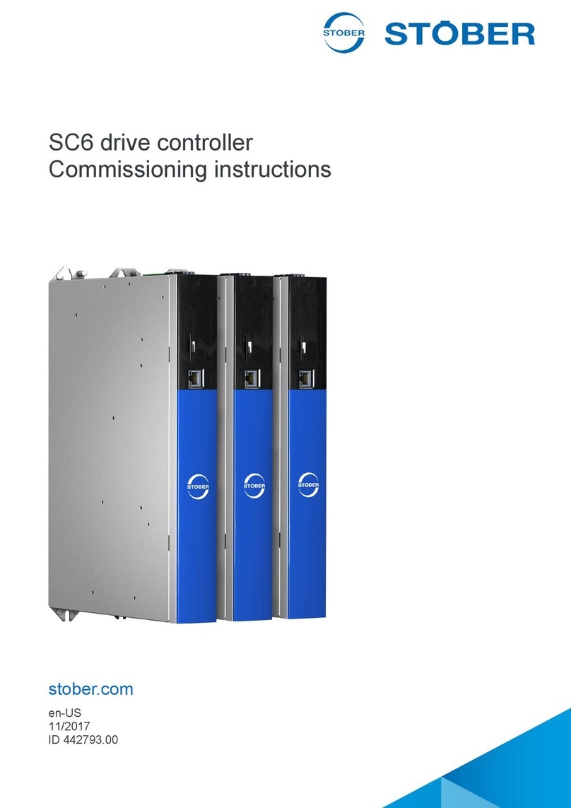
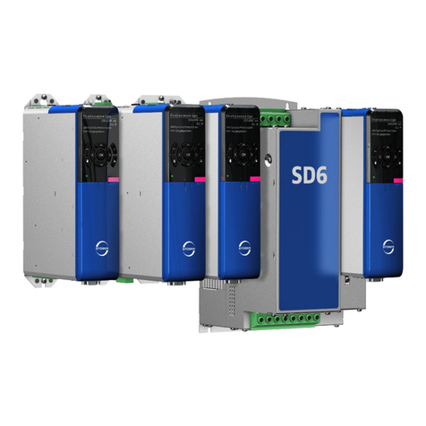
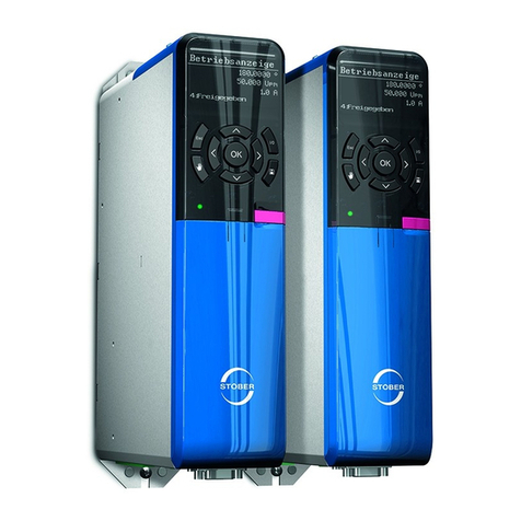
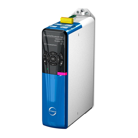
Stober SD6 Series User manual

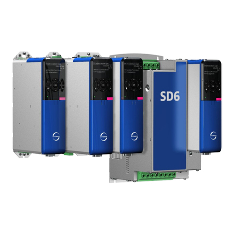
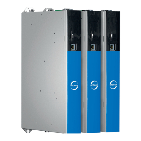
SD6 drive controller
Manual
en-US
04/2018
ID 442426.07
stober.com

Table of contents STOBER
ii
04/2018 | ID 442426.07
Table of contents
1 Foreword .............................................................................................................................. 9
2 User information................................................................................................................ 10
2.1 Storage and transfer ...................................................................................................10
2.2 Described product type...............................................................................................10
2.3 Timeliness...................................................................................................................10
2.4 Original language........................................................................................................10
2.5 Limitation of liability.....................................................................................................10
2.6 Formatting conventions ..............................................................................................11
2.6.1 Use of symbols............................................................................................. 11
2.6.2 Markup of text elements ............................................................................... 12
2.7 Symbols, marks and test symbols ..............................................................................13
2.8 Trademarks.................................................................................................................14
2.9 Licenses......................................................................................................................14
3 General safety instructions .............................................................................................. 15
3.1 Directives and standards ............................................................................................15
3.2 Qualified personnel.....................................................................................................15
3.3 Intended use ...............................................................................................................16
3.4 Transport and storage ................................................................................................16
3.5 Operational environment and operation .....................................................................16
3.6 Working on the machine .............................................................................................17
3.7 Disposal ...................................................................................................................... 17
4 UL-compliant use .............................................................................................................. 18
5 System configuration........................................................................................................ 20
5.1 Hardware components................................................................................................21
5.1.1 Drive controller ............................................................................................. 21
5.1.2 Controller...................................................................................................... 24
5.1.3 Operating motors, encoders and brakes ...................................................... 25
5.1.4 Accessories .................................................................................................. 26
5.2 Software components .................................................................................................36
5.2.1 Project configuration and parameterization.................................................. 36
5.2.2 Applications .................................................................................................. 36
6 Technical data.................................................................................................................... 37
6.1 Drive controllers..........................................................................................................37
6.1.1 General technical data.................................................................................. 37
6.1.2 Electrical data............................................................................................... 38

STOBER Table of contents
04/2018 | ID 442426.07
iii
6.1.3 Derating........................................................................................................ 47
6.1.4 Dimensions................................................................................................... 49
6.1.5 Weight .......................................................................................................... 52
6.2 DC link connection......................................................................................................52
6.2.1 General technical data.................................................................................. 52
6.2.2 DL6A – SD6 assignment .............................................................................. 53
6.2.3 Dimensions................................................................................................... 54
6.2.4 Weight .......................................................................................................... 55
6.3 Safety technology .......................................................................................................55
6.3.1 ST6............................................................................................................... 55
6.3.2 SE6............................................................................................................... 55
6.4 Operating motors ........................................................................................................56
6.5 Evaluable encoders ....................................................................................................58
6.5.1 Overview....................................................................................................... 58
6.5.2 Signal transmission ...................................................................................... 60
6.5.3 Drive controller ............................................................................................. 60
6.5.4 Terminal module........................................................................................... 63
6.5.5 Encoder adapter box .................................................................................... 71
6.6 Terminal module .........................................................................................................73
6.6.1 XI6 ................................................................................................................ 73
6.6.2 RI6................................................................................................................ 75
6.6.3 IO6................................................................................................................ 77
6.6.4 Weight .......................................................................................................... 78
6.7 Controllable brakes.....................................................................................................79
6.7.1 X5 ................................................................................................................. 79
6.7.2 X8 (SE6 option) ............................................................................................ 79
6.8 Evaluable motor temperature sensors........................................................................80
6.9 Braking resistor...........................................................................................................80
6.9.1 FZMU, FZZMU tubular fixed resistor ............................................................ 81
6.9.2 GVADU, GBADU flat resistor ....................................................................... 83
6.9.3 FGFKU steel-grid fixed resistor .................................................................... 86
6.9.4 RB 5000 rear section braking resistor .......................................................... 88
6.10 Choke .........................................................................................................................90
6.10.1 TEP power choke ......................................................................................... 90
6.10.2 TEP output choke......................................................................................... 93
6.11 Encoder adapter box ..................................................................................................97
6.11.1 Dimensions................................................................................................... 97
6.11.2 Weight .......................................................................................................... 97
7 Project configuration ........................................................................................................ 98
7.1 Drive controllers..........................................................................................................98

Table of contents STOBER
iv
04/2018 | ID 442426.07
7.2 DC link connection......................................................................................................98
7.2.1 Information on design and operation............................................................ 99
7.2.2 Design ........................................................................................................ 100
7.3 Mixed operation ........................................................................................................102
8 Storage ............................................................................................................................. 104
8.1 Drive controller..........................................................................................................104
8.1.1 Annual reforming ........................................................................................ 105
8.1.2 Reforming before commissioning............................................................... 106
9 Installation........................................................................................................................ 108
9.1 Safety instructions for installation .............................................................................108
9.2 Basic assembly instructions......................................................................................108
9.3 Minimum clearances.................................................................................................110
9.4 Drilling diagram and dimensions...............................................................................111
9.5 Length of copper rails ...............................................................................................113
9.6 Installing the communication module........................................................................114
9.7 Installing the terminal module ...................................................................................115
9.8 Installing the drive controller without a rear section module .....................................116
9.9 Installing the DC link connection...............................................................................117
9.10 Installing a rear section braking resistor ...................................................................118
9.11 Mounting the drive controller on the rear section module.........................................119
9.12 Attaching the EMC shroud........................................................................................122
9.13 Installing the encoder adapter box............................................................................123
10 Connection....................................................................................................................... 124
10.1 Safety instructions for connection.............................................................................124
10.2 Line routing ...............................................................................................................124
10.3 Protective measures .................................................................................................125
10.3.1 Power grid supply in parallel operation....................................................... 125
10.3.2 Line fuse..................................................................................................... 126
10.3.3 Grid connection in parallel operation.......................................................... 131
10.3.4 Residual current protective device ............................................................. 131
10.3.5 Housing grounding ..................................................................................... 133
10.3.6 EMC recommendations.............................................................................. 134
10.4 Drive controller..........................................................................................................135
10.4.1 Overview with ST6 safety module .............................................................. 135
10.4.2 Overview with SE6 safety module.............................................................. 141
10.4.3 X1: Enable and relay 1 ............................................................................... 147
10.4.4 X2: Motor temperature sensor.................................................................... 147
10.4.5 X3A, X3B: PC, IGB..................................................................................... 149

STOBER Table of contents
04/2018 | ID 442426.07
v
10.4.6 X4: Encoder................................................................................................ 150
10.4.7 X5: Brake – Actuation................................................................................. 153
10.4.8 X6: Brake – Feedback and supply (ST6 option)......................................... 154
10.4.9 X7: Brake 2 – Supply (SE6 option)............................................................. 155
10.4.10 X8: Brake 2 – Safe brake control (SE6 option)........................................... 156
10.4.11 X10: 230/400V supply ............................................................................... 157
10.4.12 X11: 24V supply ........................................................................................ 160
10.4.13 X12: Safety technology (ST6 option).......................................................... 161
10.4.14 X14: Safety technology – Safe inputs (SE6 option).................................... 162
10.4.15 X15: Safety technology – Safe outputs, supply for X50 (SE6 option) ........ 163
10.4.16 X20: Motor.................................................................................................. 164
10.4.17 X30: DC link connection, braking resistor................................................... 169
10.4.18 X50: Plausibility encoder (SE6 option) ....................................................... 170
10.4.19 Connecting a drive controller (ST6 option)................................................. 171
10.4.20 Connecting a drive controller (SE6 option)................................................. 173
10.5 Communication module ............................................................................................175
10.5.1 EC6 – EtherCAT......................................................................................... 175
10.5.2 CA6 – CANopen......................................................................................... 177
10.5.3 PN6 – PROFINET ...................................................................................... 178
10.6 Terminal module .......................................................................................................180
10.6.1 XI6 .............................................................................................................. 180
10.6.2 RI6.............................................................................................................. 190
10.6.3 IO6.............................................................................................................. 204
10.7 Encoder adapter box ................................................................................................208
10.7.1 LA6 for synchronous linear motors............................................................. 209
10.8 Cables.......................................................................................................................216
10.8.1 Power cables.............................................................................................. 217
10.8.2 Encoder cables........................................................................................... 222
11 Operation.......................................................................................................................... 237
11.1 Overview...................................................................................................................237
11.2 Menu structure and navigation .................................................................................238
12 Commissioning................................................................................................................ 240
12.1 Initiating the project...................................................................................................240
12.1.1 Projecting the drive controller and axis....................................................... 240
12.1.2 Configuring the safety module.................................................................... 241
12.1.3 Creating other modules and drive controllers............................................. 242
12.1.4 Specifying a module ................................................................................... 242
12.1.5 Specifying the project ................................................................................. 242
12.2 Mechanical drive model ............................................................................................243
12.2.1 Parameterizing the STOBER motor ........................................................... 243
12.2.2 Parameterizing the axis model ................................................................... 243

Table of contents STOBER
vi
04/2018 | ID 442426.07
12.3 Testing the project configuration...............................................................................246
12.3.1 Test using DriveControlSuite...................................................................... 246
12.3.2 Test using the operating unit of the drive controller.................................... 249
13 Communication ............................................................................................................... 251
13.1 System requirements................................................................................................251
13.1.1 Personal firewall ......................................................................................... 251
13.1.2 Protocols and ports for communication using routers ................................ 252
13.1.3 IGB and IGB motion bus network............................................................... 252
13.2 Direct connection ......................................................................................................254
13.3 Remote maintenance................................................................................................254
13.4 IGB motion bus .........................................................................................................254
13.5 Fieldbus ....................................................................................................................254
14 Diagnostics ...................................................................................................................... 255
14.1 Drive controllers........................................................................................................255
14.1.1 Drive controller state................................................................................... 255
14.1.2 Service network connection........................................................................ 257
14.1.3 IGB state..................................................................................................... 258
14.1.4 Fieldbus state ............................................................................................. 259
14.1.5 Fieldbus network connection...................................................................... 261
14.2 Events.......................................................................................................................263
14.2.1 Overview..................................................................................................... 263
14.2.2 Event 31: Short/ground............................................................................... 265
14.2.3 Event 32: Short/ground internal.................................................................. 265
14.2.4 Event 33: Overcurrent ................................................................................ 266
14.2.5 Event 34: Hardware fault............................................................................ 267
14.2.6 Event 35: Watchdog ................................................................................... 267
14.2.7 Event 36: High voltage ............................................................................... 268
14.2.8 Event 37: Motor encoder ............................................................................ 269
14.2.9 Event 38: Temperature drive controller sensor .......................................... 271
14.2.10 Event 39: Overtemperature drive controller i2t........................................... 273
14.2.11 Event 40: Invalid data................................................................................. 274
14.2.12 Event 41: Temp.MotorTMP ........................................................................ 275
14.2.13 Event 42: TempBrakeRes .......................................................................... 276
14.2.14 Event 43: AE1 wire break........................................................................... 277
14.2.15 Event 44: External fault 1 ........................................................................... 278
14.2.16 Event 45: Overtemp.motor i2t..................................................................... 279
14.2.17 Event 46: Low voltage ................................................................................ 280
14.2.18 Event 47: Torque limit................................................................................. 281
14.2.19 Event 48: Brake release control ................................................................. 282
14.2.20 Event 49: Brake.......................................................................................... 282
14.2.21 Event 50: Safety module ............................................................................ 284
14.2.22 Event 51: Virtual master limit switch........................................................... 285

STOBER Table of contents
04/2018 | ID 442426.07
vii
14.2.23 Event 52: Communication .......................................................................... 286
14.2.24 Event 53: Limit switch................................................................................. 288
14.2.25 Event 54: Following error............................................................................ 290
14.2.26 Event 55: Option module............................................................................ 291
14.2.27 Event 56: Overspeed.................................................................................. 293
14.2.28 Event 57: Runtime usage ........................................................................... 294
14.2.29 Event 58: Encoder simulation..................................................................... 295
14.2.30 Event 59: Overtemperature drive controller i2t........................................... 296
14.2.31 Event 60: Application event 0 – Event 67: Application event 7 .................. 297
14.2.32 Event 68: External fault 2 ........................................................................... 298
14.2.33 Event 69: Motor connection........................................................................ 299
14.2.34 Event 70: Parameter consistency............................................................... 300
14.2.35 Event 71: Firmware .................................................................................... 301
14.2.36 Event 72: Brake test timeout – Event 75: Axis 4 brake test timeout........... 302
14.2.37 Event 76: Position encoder......................................................................... 303
14.2.38 Event 77: Master encoder .......................................................................... 305
14.2.39 Event 78: Position limit cyclic ..................................................................... 308
14.2.40 Event 79: Motor / position monitor.............................................................. 309
14.2.41 Event 80: Illegal action ............................................................................... 310
14.2.42 Event 81: Motor allocation.......................................................................... 310
14.2.43 Event 82: Hall sensor ................................................................................. 311
14.2.44 Event 83: Failure of one/ all phases (mains) .............................................. 312
14.2.45 Event 84: Drop in network voltage when power section active .................. 313
14.2.46 Event 85: Excessive jump in reference value............................................. 314
14.2.47 Event 88: Control panel.............................................................................. 315
15 Replacement .................................................................................................................... 316
15.1 Safety instructions for device replacement ...............................................................316
15.2 Notes on the safety configuration .............................................................................316
15.3 Replacing the drive controller ...................................................................................317
15.4 Replacing or updating the firmware ..........................................................................319
16 Service.............................................................................................................................. 320
16.1 STOBER electronics service ....................................................................................320
16.2 Creating reverse documentation...............................................................................321
16.2.1 Drive controller without SE6 option ............................................................ 321
16.2.2 Drive controller with SE6 option ................................................................. 322
17 Appendix .......................................................................................................................... 325
17.1 Terminal specifications .............................................................................................325
17.1.1 Overview..................................................................................................... 325
17.1.2 FMC 1,5 -ST-3,5......................................................................................... 327
17.1.3 FK-MCP 1,5 -ST-3,5................................................................................... 328
17.1.4 BCF 3,81 180 SN ....................................................................................... 329

Table of contents STOBER
viii
04/2018 | ID 442426.07
17.1.5 BFL 5.08HC 180 SN................................................................................... 330
17.1.6 BLDF 5.08 180 SN ..................................................................................... 331
17.1.7 DFMC 1.5 -ST-3.5 ...................................................................................... 332
17.1.8 GFKC 2,5 -ST-7,62..................................................................................... 333
17.1.9 GFKIC 2.5 -ST-7.62.................................................................................... 334
17.1.10 SPC 5 -ST-7,62 .......................................................................................... 335
17.1.11 ISPC 5 -STGCL-7,62.................................................................................. 336
17.1.12 SPC 16 -ST-10,16 ...................................................................................... 337
17.1.13 ISPC 16 -ST-10,16 ..................................................................................... 338
17.1.14 MKDSP 25 -15,00....................................................................................... 339
17.2 Wiring examples .......................................................................................................340
17.2.1 Stand-alone operation with direct brake control ......................................... 340
17.2.2 Stand-alone operation with indirect brake control ...................................... 341
17.2.3 Parallel operation........................................................................................ 342
17.3 Device addressing ....................................................................................................343
17.4 Detailed information..................................................................................................344
17.5 Symbols in formulas .................................................................................................345
17.6 Abbreviations ............................................................................................................347
18 Contact ............................................................................................................................. 349
18.1 Consultation, service and address............................................................................349
18.2 Your opinion is important to us .................................................................................349
18.3 Close to customers around the world .......................................................................350
Glossary ........................................................................................................................... 351
List of figures................................................................................................................... 356
List of tables .................................................................................................................... 358

STOBER 1 | Foreword
04/2018 | ID 442426.07
9
1 Foreword
The SD6 drive controller from the the 6th STOBER drive controller generation offers maximum
precision and productivity for automation technology and machine manufacturing despite ever
more complex functions. Highly dynamic drives ensure the shortest recovery times from fast
changes in reference value and load jumps. There is also an option of connecting the drive
controllers in a DC intermediate circuit for multi-axis applications, which improves the energy
footprint of the entire system. The SD6 drive controller is available in four sizes with a nominal
output current of up to 85A.
Features
§Control of linear and rotary synchronous servo motors and asynchronous motors
§Multi-functional encoder interfaces
§Automatic motor parameterization from the electronic motor nameplate
§Isochronic system bus (IGB motion bus) for parameterization and multi-axis applications
§Communication over CANopen, EtherCAT or PROFINET
§Safe Torque Off (STO) in the standard version, expanded safety technology (SIL3,
PLe,Cat.4) as an option
§Digital and analog inputs and outputs
§Brake chopper, brake control and line filter
§Flexible DC link connection for multi-axis applications
§Convenient operating unit consisting of graphical display and keys
§Paramodul removable data storage for quick commissioning and service

2 | User information STOBER
10
04/2018 | ID 442426.07
2 User information
This documentation covers the SD6 drive controller. You will receive support for the assembly of
the individual modules along with the associated components that you will need to operate the
drive controllers in the control cabinet.
You will also find information on wiring the modules correctly and checking their functionality in
the group with an initial test.
More detailed information on project configuration and diagnostics are additional topics covered
in this manual.
Information
To ensure proper functionality, we recommend using cables from STOBER that are matched to
the complete system. In case of use of unsuitable connection cables, we reserve the right to
reject claims under the warranty.
2.1 Storage and transfer
As this documentation contains important information for handling the product safely and
efficiently, it must be stored in the immediate vicinity of the product until product disposal and be
accessible to qualified personnel at all times.
Also pass on this documentation if the product is transferred or sold to a third party.
2.2 Described product type
This documentation is binding for:
SD6 drive controller in combination with
DriveControlSuite software in V 6.3-C or later and associated firmware in V 6.3-C or later.
2.3 Timeliness
Check whether this document is the most up-to-date version of the documentation. We provide
the latest document versions for our products for download on our website: http://
www.stoeber.de/en/download.
2.4 Original language
The original language of this documentation is German; all other language versions are derived
from the original language.
2.5 Limitation of liability
This documentation was created taking into account the applicable standards and regulations
as well as the current state of technology.
STOBER shall assume no responsibility for damage resulting from failure to comply with the
documentation or from use that deviates from the intended use of the product. This is especially
true for damage caused by individual technical modifications to the product or projecting and
operation of the product by unqualified personnel.

STOBER 2 | User information
04/2018 | ID 442426.07
11
2.6 Formatting conventions
Orientation guides in the form of signal words, symbols and special text markups are used to
emphasize specific information so that you are able identify it in this documentation quickly.
2.6.1 Use of symbols
Safety instructions are identified with the following symbols. They indicate special risks when
handling the product and are accompanied by relevant signal words that express the extent of
the risk. Furthermore, useful tips and recommendations for efficient, error-free operation are
specially highlighted.
ATTENTION!
Notice
This indicates that damage to property may occur
▪ if the stated precautionary measures are not taken.
CAUTION!
Caution
This word with a warning triangle indicates that minor personal injury may occur
▪ if the stated precautionary measures are not taken.
WARNING!
Warning
This word with a warning triangle means there may be a considerable risk of fatal injury
▪ if the stated precautionary measures are not taken.
DANGER!
Danger
This word with a warning triangle indicates that there is a considerable risk of fatal injury
▪ if the stated precautionary measures are not taken.
Information
Information indicates important information about the product or serves to emphasize a section
in the documentation that deserves special attention from the reader.

2 | User information STOBER
12
04/2018 | ID 442426.07
2.6.2 Markup of text elements
Certain elements of the continuous text are distinguished as follows.
Quick DC-Link module Words or expressions with a special meaning
Detailed information Internal cross-reference
http://www.stoeber.de External cross-reference
Software and display indicators
The following formatting is used to identify the various information content of elements
referenced by the software interface or the drive controller display, as well as any user entries.
Main menu
Settings
Window names, dialog names, page names or buttons,
combined proper nouns, functions referenced by the
interface
Select
Referencing method A
Predefined entry
Save your
<own IP address>
User-defined entry
EVENT 52:
COMMUNICATION
Display indicators (status, messages, warnings, faults)
for status information referenced by the interface
Keyboard shortcuts and command sequences or paths are represented as follows.
[CTRL], [CTRL] +
[S]
Key, shortcut
Table > Insert table Navigation to menus/submenus (path specification)
Buttons
The buttons of the drive controller are depicted as follows in .
[OK]
OK
Interpretation of parameter identification
Parameter identification consists of the following elements, where short forms are also possible,
i.e. only specifying a coordinate or the combination of coordinate and name.
E50 Drive controller G6 0
Coordinate
Name
Version
Drive controller
generation/series

STOBER 2 | User information
04/2018 | ID 442426.07
13
2.7 Symbols, marks and test symbols
EN 61558-2-20
Choke without overload protection.
Grounding symbol
Grounding symbol in accordance with IEC 60417-5019
(DB:2002-10).
RoHS lead-free mark
Marking in accordance with RoHS directive 2011-65-EU.
CE mark
Manufacturer's self declaration: The product meets the
requirements of EU directives.
UL test symbol
This product is listed by UL for the United States and Canada.
Representative samples of this product have been evaluated by
UL and meet the requirements of applicable standards.
UL recognized component mark
This component or material is recognized by UL. Representative
samples of this product have been evaluated by UL and meet
applicable requirements.

2 | User information STOBER
14
04/2018 | ID 442426.07
2.8 Trademarks
The following names used in connection with the device, its optional equipment and its
accessories are trademarks or registered trademarks of other companies:
CANopen®,
CiA®
CANopen® and CiA® are registered European Union trademarks
of CAN in AUTOMATION e.V., Nuremberg, Germany.
EnDat®EnDat® and the EnDat® logo are registered trademarks of Dr.
Johannes Heidenhain GmbH, Traunreut, Germany.
EtherCAT®,
Safety over EtherCAT®,
TwinCAT®
EtherCAT®, Safety over EtherCAT® and TwinCAT® are registered
trademarks of patented technologies licensed by Beckhoff
Automation GmbH, Verl, Germany.
HIWIN®The HIWIN logo is a registered trademark of HIWIN
TECHNOLOGIES CORP., Taichung, Taiwan.
Microsoft®,
Windows®,
Windows® XP,
Windows® 7,
Windows® 10
Microsoft®, Windows®, the Windows® logo, Windows® XP,
Windows® 7 and Windows® 10 are registered trademarks of
Microsoft Corporation in the United States and/or other countries.
PLCopen®PLCopen® is a registered trademark of the PLCopen
Organisation, Gorinchem, Netherlands.
PROFIBUS®,
PROFINET®
The PROFIBUS and the PROFINET logo are registered
trademarks of PROFIBUS Nutzerorganisation e.V., Karlsruhe,
Germany.
speedtec®, springtec®speedtec® and springtec® are registered trademarks of TE
Connectivity Industrial GmbH, 94559 Niederwinkling, Germany.
All other trademarks not listed here are the property of their respective owners.
Products that are registered as trademarks are not specially indicated in this documentation.
Existing property rights (patents, trademarks, protection of utility models) are to be observed.
2.9 Licenses
Software from the following licensor is used in SD6:
SEGGER Microcontroller GmbH & Co. KG
In den Weiden 11
40721 Hilden
Germany
Phone+49 2103-2878-0
Fax+49 2103-2878-28
E-mail: [email protected]
Internet: http://www.segger.com

STOBER 3 | General safety instructions
04/2018 | ID 442426.07
15
3 General safety instructions
There are risks associated with the product described in this documentation that can be
prevented by complying with the described warning and safety instructions as well as the
included technical rules and regulations.
3.1 Directives and standards
The following European directives and standards are relevant to the product specified in this
documentation:
§Machinery Directive 2006/42/EC
§Low Voltage Directive 2014/35/EU
§EMC Directive 2014/30/EU
§EN 61326-3-1:2008
§EN 61800-3:2004 and A1:2012
§EN 61800-5-1:2007
§EN 61800-5-2:2007
§EN 50178:1997
Subsequent references to the standards do not specify the respective year in order to improve
readability.
§Low Voltage Directive 2014/35/EU
§EMC Directive 2014/30/EU
3.2 Qualified personnel
In order to be able to perform the tasks described in this documentation, the persons instructed
to perform them must have the appropriate professional qualification and be able to assess the
risks and residual hazards when handling the products. For this reason, all work on the products
as well as their operation and disposal may be performed only by professionally qualified
personnel.
Qualified personal are persons who have acquired authorization to perform these tasks either
through training to become a specialist and/or instruction by specialists.
Furthermore, valid regulations, legal requirements, applicable basic rules, this documentation
and the safety instructions included in it must be carefully read, understood and observed.

3 | General safety instructions STOBER
16
04/2018 | ID 442426.07
3.3 Intended use
As defined by DIN EN 50178, SD6 drive controllers are electrical devices operating as power
electronics to control the flow of energy in high-voltage systems. They are intended solely for
the operation of synchronous servo motors, asynchronous motors, linear motors or torque
motors.
The connection of other electronic loads or operation outside applicable technical specifications
constitutes improper use.
EMC-compliant installation
The SD6 drive controller and accessories must be installed and wired compliant for EMC
Modification
As the user, you may not make any physical, technical or electrical modifications to the SD6
drive controller and the accessories.
Maintenance
The SD6 drive controller and accessories do not require maintenance. For the safety module,
take appropriate measures to detect or prevent possible errors in the connection wiring.
Product life span
A drive controller with integrated safety module must be taken out of operation 20 years after
the production date. The production date of the drive controller is found on the accompanying
nameplate.
3.4 Transport and storage
Inspect the delivery for any transport damage immediately after you receive it. Notify the
transport company of any damage immediately. Do not put a damaged product into operation.
To ensure the faultless and safe operation of the products, they must be professionally set up,
installed, operated and maintained. If you have to transport or store the products, you must
protect them from mechanical impacts and vibrations as well as observe the recommended
transport and storage conditions in the technical data.
Store the products in a dry and dust-free room if you do not install them immediately.
3.5 Operational environment and operation
The products are subject to sales restrictions in accordance with IEC 61800-3.
The products are not designed for use in a public low-voltage network that supplies residential
areas. Radio-frequency interference can be expected if the products are used in this type of
network.
The products are designed exclusively for operation in TN networks.
The products are intended exclusively for installation in control cabinets with at least protection
class IP54.
Always operate the products within the limits specified by the technical data.

STOBER 3 | General safety instructions
04/2018 | ID 442426.07
17
The following applications are prohibited:
§Use in potentially explosive atmospheres
§Use in environments with harmful substances as specified by EN 60721, such as oils, acids,
gases, vapors, dust and radiation
Implementation of the following applications is permitted only after approval from STOBER:
§Use in non-stationary applications
§The use of active components (drive controllers, supply modules, energy recovery units or
discharge units) from third-party manufacturers
The drive controller is exclusively intended for operation in TN networks and only suitable for
use in supply grids. At 480VAC, the drive controllers are permitted to supply a maximum
symmetrical nominal short-circuit current in accordance with the following table:
Size Max. symm. nominal short-circuit current
Size 0 – Size 2 5000A
Size 3 10000A
Tab. 1: Maximum symmetrical nominal short-circuit current of the drive controller
3.6 Working on the machine
Apply the 5 safety rules in the order stated before performing any work on the machine:
§Disconnect (also ensure that the auxiliary circuits are disconnected).
§Protect against being turned on again.
§Check that voltage is not present.
§Ground and short circuit.
§Cover adjacent live parts.
Information
Note that the you can only determine that voltage is no longer present once the discharge time
has elapsed. The discharge time depends on the self-discharge of the drive controller. You can
find the discharge time in the general technical data.
3.7 Disposal
Observe the current national and regional regulations when disposing of the product! Dispose of
the individual product parts depending on their properties, e.g. as:
§Electronic waste (circuit boards)
§Plastic
§Sheet metal
§Copper
§Aluminum
§Battery

4 | UL-compliant use STOBER
18
04/2018 | ID 442426.07
4 UL-compliant use
This chapter contains relevant information for use under UL conditions (UL – Underwriters
Laboratories).
Surrounding temperature and pollution degree
The maximum surrounding temperature for UL-compliant operation is 45°C. For use in an
environment with some degree of pollution, note the information in chapter General technical
data [}37].
Network layout
All device types supplied with 480VAC are intended solely for operation with wye sources at
480/277VAC.
Power supply and motor overload protection
Observe the specification of I2maxPU at 8kHz clock frequency in the electrical data of the drive
controller; see the chapter Electrical data [}38].
Line fuse
For UL-compliant line fuses, observe the specifications in the chapter UL-compliant line fuse
[}128].
In accordance with CSA-C22.2 No. 14-13, the following applies for use in Canada:
Depending on the device type, additional overvoltage protection must be installed in the network
upstream of the device and must fulfill the following conditions.
§Single-phase – SD6A02:
• Overvoltage category 3
• Phase-ground = 240VAC (peak permitted rated surge voltage = 4kV)
• Phase-phase (or N) = 240VAC (peak permitted rated surge voltage = 4kV)
§Three-phase – from SD6A04:
• Overvoltage category 3
• Phase-ground = 277VAC (peak permitted rated surge voltage = 4kV)
• Phase-phase (or N) = 480VAC (peak permitted rated surge voltage = 6kV)
Motor protection
All models of the 6th STOBER drive controller generation feature a certified i²t model, a
computational model for thermal monitoring of the motor. This fulfills the requirements for solid
state motor overload protection in accordance with the amendment to UL508C from May 2013.
In order to activate it and start the protective function, set the parameters as follows (deviating
from the default values): U10 = 2:Warning and U11 = 1.00s. This model can be used instead of
or in addition to temperature-monitored motor protection, as described in the chapter X2: Motor
temperature sensor [}147].

STOBER 4 | UL-compliant use
04/2018 | ID 442426.07
19
Motor temperature sensor
The SD6 drive controller features connections for PTC thermistors (NAT 145°C), KTY
temperature sensors (KTY84-130) or Pt temperature sensors (Pt1000). For a proper
connection, observe the terminal description for X2 in the chapter X2: Motor temperature sensor
[}147].
Information
STOBER recommends the use of PTC thermistors as thermal motor protection.
Braking resistor
If the drive controller is to be provided with an externally mounted braking resistor, overheat
protection must be provided separately.
24V supply
Low-voltage circuits must be supplied by an isolated source with a maximum output voltage that
does not exceed 30VDC. Also note the technical specifications for terminal X11 in the chapter
X11: 24V supply [}160].
Conductors
Use only copper conductors for a surrounding temperature of 60/75°C.
Fuses
Fuses must be approved in accordance with UL 248.
§Use a 1A fuse (time delay) upstream of relay 1. Observe the terminal description for X1, pin
1 in the chapter X1: Enable and relay 1 [}147].
§Provide the supply for the brake using a 4A fuse (time delay). Observe the terminal
description for X6 in the chapter X6: Brake – Feedback and supply (ST6 option) [}154].
§The following applies to interface extensions with terminal module XI6, RI6 or IO6: Provide
the 24VDC supply using a 1A fuse (time delay). Observe the terminal description for X101,
pin 18 or 19 in the chapter X101: BE1 – BE5, BA1 – BA2 [}182].
Branch circuit protection
The integral solid state short circuit protection does not provide branch circuit protection. If you
would like to branch the output of the drive controller, branch circuit protection must be ensured
in coordination with STOBER and in compliance with the National Electrical Code as well as all
additional applicable local regulations or equivalent provisions.
UL test
Only the risks of electric shock and the risk of fire have been examined during UL acceptance at
STOBER. Functional safety aspects have not been assessed during the UL approval process.
These are assessed for STOBER by bodies such as the TÜV SÜD certification service.

5 | System configuration STOBER
20
04/2018 | ID 442426.07
5 System configuration
The SD6 drive controller features a modular interface concept that offers you the variable
combination of all interface components (terminals, fieldbus, encoders and safety technology).
For the communication between multiple drive controllers, the IGB motion bus isochronic
system bus is available for multi-axis applications.
In multi-axis applications with decentralized motion control, we recommend the drive-based
application STOBER Drive Based. Alternatively, you can implement the application using a CiA
402 interface. You commission the drive controller using the DriveControlSuite software.
You can also connect multiple SD6 drive controllers in an intermediate circuit and thus improve
the energy footprint of the entire system. For this purpose, you will need an appropriate Quick
DC-Link module for each drive controller.
The drive controllers provide the STO safety function in accordance with EN 61800-5-2.
The following graphic explains the principle system configuration.
MC6 motion controller
Field bus
4 x SD6 drive controllers
Commissioning
Command levelController levelField level
Synchronous
servo motors and
asynchronous motors
Safety
Actuator/sensor level,
electromechanics
Fig.1: System overview
Other manuals for SD6 Series
7
Table of contents
Other Stober Controllers manuals

Stober
Stober SD6 Series User manual

Stober
Stober SR6 Training manual

Stober
Stober MC6 User manual

Stober
Stober SD6 Series Training manual

Stober
Stober SD6 Series User manual

Stober
Stober MC6 User manual

Stober
Stober SD6 Series Training manual

Stober
Stober SC6 Series Training manual

Stober
Stober SC6 Series Training manual

Stober
Stober CiA 402 User manual