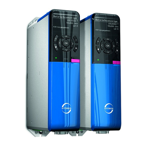
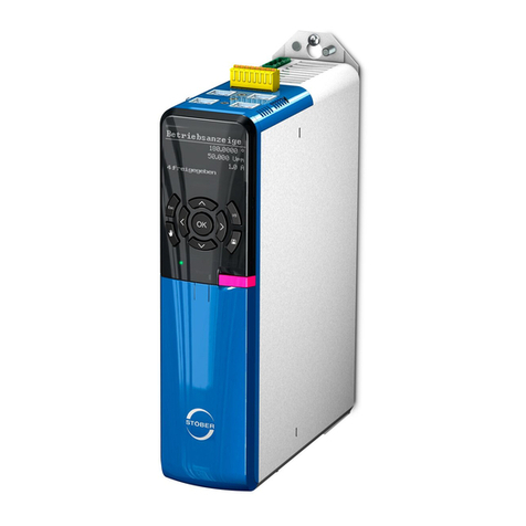
Stober SD6 Series Training manual

SD6
Commissioning Instructions
442537.0101/2015en

ID 442537.01 2WE KEEP THINGS MOVING
Table of contents
Commissioning Instructions SD6
Table of contents
1 General Information . . . . . . . . . . . . . . . . . . . . . . . . . . . . . . .. . . . .4
1.1 About this documentation . . . . . . . . . . . . . . . . . . . . . . . . . . . . . . 4
1.2 Other manuals .. . . . . . . . . . . . . . . . . . . . . . . . . . . . . . . . . . . . . . 4
1.3 Further support . . . . . . . . . . . . . . . . . . . . . . . . . . . . . . . . . . . . . . 5
1.4 Abbreviations, symbols, indexes . . . . . . . . . . . . . . . . . . . . . . . . . 5
1.5 Symbols, identifiers, marks . . . . . . . . . . . . . . . . . . . . . . . . . . . . . 6
2 Notes on safety .. . . . . . . . . . . . . . . . . . . . . . . . . . . . . . . . . . .. . . . .7
2.1 Operation in accordance with its intended use . . . . . . . . . . . . . . 7
2.2 Component part of the product . . . . . . . . . . . . . . . . . . . . . . . . . . 7
2.3 Risk assessment . . . . . . . . . . . . . . . . . . . . . . . . . . . . . . . . . . . . . 7
2.4 Qualified personnel . . . . . . . . . . . . . . . . . . . . . . . . . . . . . . . . . . . 7
2.5 Working on the machine . . . . . . . . . . . . . . . . . . . . . . . . . . . . . . . 8
2.6 Disposal .. . . . . . . . . . . . . . . . . . . . . . . . . . . . . . . . . . . . . . . . . . . 8
2.7 Presentation of notes on safety .. . . . . . . . . . . . . . . . . . . . . . . . . 8
3 Technical data . . . . . . . . . . . . . . . . . . . . . . . . . . . . . . . . . . . . .. . . . .9
3.1 Notes on safety . . . . . . . . . . . . . . . . . . . . . . . . . . . . . . . . . . . . . . 9
3.2 Nameplate . . . . . . . . . . . . . . . . . . . . . . . . . . . . . . . . . . . . . . . . . . 9
3.3 Type designation . . . . . . . . . . . . . . . . . . . . . . . . . . . . . . . . . . . . 10
3.4 Sizes . . . . . . . . . . . . . . . . . . . . . . . . . . . . . . . . . . . . . . . . . . . . . 11
3.5 Electrical Data . . . . . . . . . . . . . . . . . . . . . . . . . . . . . . . . . . . . . . 11
3.5.1 Control board . . . . . . . . . . . . . . . . . . . . . . . . . . . . . . . 11
3.5.2 Power board . . . . . . . . . . . . . . . . . . . . . . . . . . . . . . . . 12
3.6 Mechanical Data . . . . . . . . . . . . . . . . . . . . . . . . . . . . . . . . . . . . 15
3.6.1 Device features . . . . . . . . . . . . . . . . . . . . . . . . . . . . . 15
3.6.2 Dimensions .. . . . . . . . . . . . . . . . . . . . . . . . . . . . . . . . 16
4Installation. . . . . . . . . . . . . . . . . . . . . . . . . . . . . . . . . . . . . . . . . . . .18
4.1 Notes on safety . . . . . . . . . . . . . . . . . . . . . . . . . . . . . . . . . . . . . 18
4.2 Drive controller .. . . . . . . . . . . . . . . . . . . . . . . . . . . . . . . . . . . . . 18
4.3 Terminal modules .. . . . . . . . . . . . . . . . . . . . . . . . . . . . . . . . . . . 19
4.4 Communication modules . . . . . . . . . . . . . . . . . . . . . . . . . . . . . . 20
4.5 Quick DC-Link . . . . . . . . . . . . . . . . . . . . . . . . . . . . . . . . . . . . . . 21
4.6 Bottom brake resistor .. . . . . . . . . . . . . . . . . . . . . . . . . . . . . . . . 22
4.7 EMC shroud .. . . . . . . . . . . . . . . . . . . . . . . . . . . . . . . . . . . . . . . 24
5 Connecting . . . . . . . . . . . . . . . . . . . . . . . . . . . . . . . . . . . . . . . . . . . .25
5.1 Notes on safety . . . . . . . . . . . . . . . . . . . . . . . . . . . . . . . . . . . . . 25
5.2 General information . . . . . . . . . . . . . . . . . . . . . . . . . . . . . . . . . . 26
5.2.1 EMC connection . . . . . . . . . . . . . . . . . . . . . . . . . . . . . 26
5.2.2 Selecting the cables . . . . . . . . . . . . . . . . . . . . . . . . . . 26
5.3 Wiring .. . . . . . . . . . . . . . . . . . . . . . . . . . . . . . . . . . . . . . . . . . . . 27
5.4 Protective measures . . . . . . . . . . . . . . . . . . . . . . . . . . . . . . . . . 27

ID 442537.01 3WE KEEP THINGS MOVING
Table of contents
Commissioning Instructions SD6
5.4.1 Line fuse .. . . . . . . . . . . . . . . . . . . . . . . . . . . . . . . . . . 27
5.4.2 Residual current safety device .. . . . . . . . . . . . . . . . . 28
5.4.3 Housing ground . . . . . . . . . . . . . . . . . . . . . . . . . . . . . 29
5.5 Drive controller . . . . . . . . . . . . . . . . . . . . . . . . . . . . . . . . . . . . . 30
5.5.1 Overview of terminals .. . . . . . . . . . . . . . . . . . . . . . . . 30
5.5.2 X1: Enable and relay 1 .. . . . . . . . . . . . . . . . . . . . . . . 35
5.5.3 X2: Motor temperature sensor . . . . . . . . . . . . . . . . . . 36
5.5.4 X3A, X3B: PC, IGB . . . . . . . . . . . . . . . . . . . . . . . . . . 37
5.5.5 X4: Encoder . . . . . . . . . . . . . . . . . . . . . . . . . . . . . . . . 38
5.5.6 X5, X6: Motor holding brake .. . . . . . . . . . . . . . . . . . . 41
5.5.7 X10: 230 V/400 V power . . . . . . . . . . . . . . . . . . . . . . 42
5.5.8 X11: 24 V power .. . . . . . . . . . . . . . . . . . . . . . . . . . . . 43
5.5.9 X12: Safety technology . . . . . . . . . . . . . . . . . . . . . . . 44
5.5.10 X20: Motor .. . . . . . . . . . . . . . . . . . . . . . . . . . . . . . . . 45
5.5.11 X30: Quick DC-Link, braking resistor . . . . . . . . . . . . . 47
5.6 Terminal modules . . . . . . . . . . . . . . . . . . . . . . . . . . . . . . . . . . . 48
5.6.1 X100 .. . . . . . . . . . . . . . . . . . . . . . . . . . . . . . . . . . . . . 48
5.6.2 X101 .. . . . . . . . . . . . . . . . . . . . . . . . . . . . . . . . . . . . . 49
5.6.3 X102 .. . . . . . . . . . . . . . . . . . . . . . . . . . . . . . . . . . . . . 52
5.6.4 X103A . . . . . . . . . . . . . . . . . . . . . . . . . . . . . . . . . . . . 53
5.6.5 X103B . . . . . . . . . . . . . . . . . . . . . . . . . . . . . . . . . . . . 54
5.6.6 X103C . . . . . . . . . . . . . . . . . . . . . . . . . . . . . . . . . . . . 55
5.6.7 X120 . . . . . . . . . . . . . . . . . . . . . . . . . . . . . . . . . . . . . . 55
5.6.8 X140 . . . . . . . . . . . . . . . . . . . . . . . . . . . . . . . . . . . . . . 58
5.7 Communication modules . . . . . . . . . . . . . . . . . . . . . . . . . . . . . . 60
5.7.1 X200, X201: EtherCAT . . . . . . . . . . . . . . . . . . . . . . . . 60
5.7.2 X200: CANopen . . . . . . . . . . . . . . . . . . . . . . . . . . . . . 60
5.8 Drive controller wiring . . . . . . . . . . . . . . . . . . . . . . . . . . . . . . . . 61
5.8.1 Examples of connections . . . . . . . . . . . . . . . . . . . . . . 62
6 Commissioning . . . . . . . . . . . . . . . . . . . . . . . . . . . . . . . . . . . . . . . .63
6.1 Drive controller – control unit . . . . . . . . . . . . . . . . . . . . . . . . . . . 63
6.1.1 Menu structure and navigation . . . . . . . . . . . . . . . . . . 64
6.2 Wiring and function test . . . . . . . . . . . . . . . . . . . . . . . . . . . . . . . 65
6.2.1 Schematic test sequence . . . . . . . . . . . . . . . . . . . . . . 65
6.2.2 Practical test sequence . . . . . . . . . . . . . . . . . . . . . . . 66
6.3 Additional parameter information .. . . . . . . . . . . . . . . . . . . . . . . 67

ID 442537.01 4WE KEEP THINGS MOVING
General Information
1
Commissioning Instructions SD6
1 General Information
The new SD6 drive controller offers maximum precision and productivity
for automation technology and machine manufacturing despite ever
more complex functions. Highly dynamic drives ensure the shortest
recovery times from fast changes in reference value and load jumps.
You also have the option of connecting the drive controllers in a DC
intermediate circuit, which improves the energy footprint of the entire
system.
Properties
• Wide power range thanks to 4 sizes
• Quick DC-Link: Innovative installation concept for the DC link
connection
• Very good control performance
• Easy to service
• Real-time cross-communication (in preparation)
• Modular safety technology (in preparation)
• Free, graphical programming in accordance with IEC 61131-3 CFC
(in preparation)
1.1 About this documentation
This documentation provides support for you in the assembly of the SD6
drive controller together with associated components such as terminal
and communication modules, EMC shrouds, chassis brake resistors
and a quick DC link.
You will also find information for wiring the drive controller correctly and
checking its functionality in the group with an initial test.
For technical data and more detailed information regarding braking
resistors and chokes, projecting a quick DC link as well as assembly
and wiring of the LA6 adapter box, please refer to the SD6 manual.
To ensure proper functionality, we recommend using cables from
STOBER (see SD6 manual). In case of use of unsuitable connection
cables, we reserve the right to reject claims under the warranty.
What is new?
1.2 Other manuals
The documentation listed in the following table provides relevant
information on the SD6 drive controller.
You can find the latest document versions at www.stoeber.de.
Index Date Changes
01 01/2015 • General corrections
Additions
• Technical Data
• Installation
• Connection
• Commissioning
Device/software Documentation Contents ID
SD6 drive controllers Manual Technical data,
installation,
connection, setup,
commissioning and
customer service
442426

ID 442537.01 5WE KEEP THINGS MOVING
General Information
1
Commissioning Instructions SD6
1.3 Further support
If you have technical questions that are not answered by this document,
please contact:
• Phone: +49 7231 582-3060
• E-mail: applications@stoeber.de
1.4 Abbreviations, symbols, indexes
Abbreviations
AES Absolute Encoder Support
BG Size
CAN Controller Area Network
CiA Can in Automation
CNC Computerized Numerical Control
DC Direct Current
EMC Electromagnetic Compatibility
RCD Residual Current protective Device
UL Underwriters Laboratories
ZK DC link
Formula symbol
CCapacity
D Derating
f Frequency
K Ratio of the DC link circuit capacity being charged in the
compound DC link system to the max. charging capacity
of the drive controllers that are supplied with power
I Current
λ(lambda) Power factor; equivalent to cos φbetween the effective
and apparent power
n Speed
p Number of pole pairs
P (Effective) power
R Resistance
T Temperature
τ(tau) Thermal time constant
tTime
UVoltage
Indices
1 Input
2 Output
amb Ambient
BBrake
BAT Battery
BR Braking resistor
CH Brake chopper
Supply Supply current
hHeight
max Maximum
min Minimum
N Nominal
Mains Mains power supply
off Off
on On
PWM Pulse Width Modulation
T Temperature
VLoss
Formula symbol

ID 442537.01 6WE KEEP THINGS MOVING
General Information
1
Commissioning Instructions SD6
1.5 Symbols, identifiers, marks The following names that are used in conjunction with the device, its
optional equipment and its accessories are trademarks or registered
trademarks of other companies:
All other trademarks that are not listed here are the property of their
respective owners.
Symbols
EN 61558-2-20
Choke without overload protection.
Grounding symbol according to IEC 60417-5019
(DB:2002-10).
Identification and test symbols
Lead-free identifier for RoHS
Lead-free identifier according to RoHS directive 2011-65-
EU.
CE mark
Manufacturer's self declaration: The product meets the
requirements of EU directives.
UL test mark
This product is listed by UL for the USA and Canada.
Representative samples of this product have been
evaluated by UL and meet the requirements of applicable
standards.
UL test marks for recognized component
This component or material is recognized by UL.
Representative samples of this product have been
evaluated by UL and meet applicable requirements.
Trademarks
CANopen,
CiA
CANopen and CiA are registered Community trademarks
of CAN in Automation e.V., Nuremberg, Germany.
EtherCAT EtherCAT and the EtherCAT logo are registered
trademarks of Beckhoff Automation GmbH, Verl,
Germany.

ID 442537.01 7WE KEEP THINGS MOVING
Notes on safety
2
Commissioning Instructions SD6
2 Notes on safety
The devices can represent a source of danger. Therefore observe
• the safety guidelines, technical rules and regulations given in the
following sections
• and points.
STOBER shall assume no liability for damage resulting from failure to
comply with the instruction manual or relevant regulations. We reserve
the right to make technical changes for the purpose of improving the
devices.
2.1 Operation in accordance with its intended
use
As defined by DIN EN 50178 (previously VDE 0160), the drive
controllers are electrical equipment operating as power electronics to
control the flow of energy in high voltage systems. They are designed
exclusively for installation in switching cabinets, protection class at least
IP54, and for supplying
• synchronous servo motors and
• asynchronous motors.
Designated use does not include connecting other electrical loads!
2.2 Component part of the product
The technical documentation is a component part of a product.
• Since the technical documentation contains important information,
always keep it handy in the vicinity of the device until the machine is
disposed of.
• If the product is sold, disposed of, or rented out, always include the
technical documentation with the product.
2.3 Risk assessment
Before the manufacturer may bring a machine onto the market, he must
conduct a risk assessment according to Machine Directive 06/42/EC.
As a result, the risks associated with the use of the machine are
determined. The risk assessment is a multi-stage and iterative process.
On no account can sufficient insight into the Machine Directive be given
as part of this documentation. For this reason, seek detailed information
about the norms and legal position. When installing the drive controller
in machines, commissioning is forbidden until it has been determined
that the machine meets the requirements of EC Directive 06/42/EC.
2.4 Qualified personnel
Devices may cause residual risks. For this reason, all work on the
devices as well as operation and disposal must only be performed by
qualified personnel who are aware of the possible dangers.
Qualified personnel are persons who have acquired the authorisation to
perform these activities by
• Training from specialists and/or
• Instruction from specialists
In addition, they must have
• read,
• understood and
• observed the applicable regulations, legal provisions, rules and
standards and existing technical documentation including the safety
information contained in it.

ID 442537.01 8WE KEEP THINGS MOVING
Notes on safety
2
Commissioning Instructions SD6
2.5 Working on the machine
Apply the 5 safety rules in the order stated before performing any work
on the machine:
1. Disconnect.
Also ensure that the auxiliary circuits are disconnected.
2. Protect against being turned on again.
3. Check that voltage is not present.
4. Ground and short circuit.
5. Cover or block off adjacent live parts.
2.6 Disposal
Please comply with the latest national and regional regulations! Dispose
of the individual parts separately depending on their nature and
currently valid regulations such as, for example:
• Electronic scrap (PCBs)
•Plastic
• Sheet metal
• Copper
• Aluminum
2.7 Presentation of notes on safety
NOTICE
Notice
means that property damage may occur
if the stated precautionary measures are not taken.
CAUTION!
Caution
with warning triangle means that minor injury may occur
if the stated precautionary measures are not taken.
WARNING!
Warning
means that there may be a serious danger of death
if the stated precautionary measures are not taken.
DANGER!
Danger
means that serious danger of death exists
if the stated precautionary measures are not taken.
Information
Note that the discharge time of the DC link capacitors is up to 5
minutes. You can only determine the absence of voltage after this
time period.
Information
refers to important information about the product or serves to
emphasize a section in the documentation to which the reader
should pay special attention.

ID 442537.01 9WE KEEP THINGS MOVING
Technical data
3
Commissioning Instructions SD6
3 Technical data
3.1 Notes on safety
Drive controllers are products subject to sales restrictions in accordance
with IEC 61800-3.
The drive controllers are not designed for use in a public low frequency
network that supplies residential areas.
In a residential environment this product may cause high-frequency
interference. If this occurs the user may be asked to take suitable
measures.
The drive controllers are not designed for use in a public low frequency
network that supplies residential areas. High-frequency interference
can be expected if the drive controllers are used in a network of this
type.
Always operate the devices within the limits specified in the technical
data.
The following applications are prohibited:
• Use in areas subject to explosion hazard
• Use in environments with harmful substances as specified by EN
60721, for example oils, acids, gases, vapors, dust and radiation
Implementation of the following applications is only permitted after
approval is obtained from STOBER:
• Use in non-stationary applications
3.2 Nameplate

ID 442537.01 10WE KEEP THINGS MOVING
Technical data
3
Commissioning Instructions SD6
UL test mark
UL and cUL (CSA-UL) certified drive controllers with corresponding test
mark meet the requirements of standards UL 508C and UL 840.
3.3 Type designation
Sample code
Explanation
Designation Value in the example Meaning
Type SD6A06TEX Drive controller type
according to the type
designation
Date 1318 Production week in format
YYWW, in the example
shown here year 2013, week
18
S/N 7000204 Serial number
Nominal connection
voltage
3 x 400 V ~
50 Hz
UL: 3 x 480 V ~ 50–
60 Hz
Nominal connection voltage
Nominal connection
power
2.5 kVA Nominal connection power
Input current 4.0 A Input current
Output data 3 x 3.4 A
0...460 V
0...700 Hz
Output data
Protection class IP20 Protection class
SD 6 A 0 6 T E X
Code Designation Design
SD Type Servo Drive
6Generation 6th generation
A, B Version
0– 3 Size
0 – 9 Power output stage (Within the size)
TSafety module ST6: Safe Torque Off (STO)
N
E
C
Communication module Empty
EC6: EtherCAT
CA6: CANopen
N
X
R
I
Terminal module Empty
XI6: Extended I/O
RI6: Resolver I/O
IO6: Standard I/O

ID 442537.01 11WE KEEP THINGS MOVING
Technical data
3
Commissioning Instructions SD6
3.4 Sizes
The drive controller SD6 includes the following types and sizes:
3.5 Electrical Data
3.5.1 Control board
Type Size
SD6A02 0
SD6A04 0
SD6A06 0
SD6A14 1
SD6A16 1
SD6A24 2
SD6A26 2
SD6A34 3
SD6A36 3
SD6A38 3
Control board
U120.4 – 28.8 V
I1maxa)
a) Depending on the accessories used.
1.5 A

ID 442537.01 12WE KEEP THINGS MOVING
Technical data
3
Commissioning Instructions SD6
3.5.2 Power board
3.5.2.1 Size 0: SD6A0x
Properties of the brake chopper
3.5.2.2 Size 1: SD6A1x
Properties of the brake chopper
Type SD6A02 SD6A04 SD6A06
U1(L1 – N) 1 x 230 V,
+20 % / -40 %,
50/60 Hz;
(L1 – N) 1 x 240 V,
50/60 Hz
(L1 – L3) 3 x 400 V,
+32 % / -50 %,
50/60 Hz;
(L1 – L3) 3 x 480 V,
50/60 Hz
I1N (fPWM = 4 kHz) 8.3 A 2.8 A 5.4 A
I1N (fPWM = 8 kHz) 6 A 2.2 A 4 A
I2N (fPWM = 4 kHz)a)
a) Note the derating for 4 kHz.
4 A 2.3 A 4.5 A
I2N (fPWM = 8 kHz)b)
b) Note the derating for 8 kHz.
3 A 1.7 A 3.4 A
I2max (fPWM = 4 kHz) 180 % for 5 s; 150 % for 30 s
I2max (fPWM = 8 kHz) 250 % for 2 s; 200 % for 5 s
fPWM Adjustable: 4, 8, 16 kHzc)
c) Note the details for the nominal output current and derating for 16 kHz.
f20 – 700 Hz
U20 – U1
PV(I2= IN) 80 W 65 W 90 W
PV(I2= 0 A) Max. 30 Wd)
d) Depending on the option modules and encoders connected.
Type SD6A02 SD6A04 SD6A06
UCHon 400 – 420 V 780 – 800 V
UCHoff 360 – 380 V 740 – 760 V
RBRmin 100 Ω
PBRmax 1.8 kW 6.4 kW
Type SD6A14 SD6A16
U1(L1 – L3) 3 400 V, +32 % / -50 %, 50/60 Hz;
(L1 – L3) 3 480 V, 50/60 Hz
I1N (fPWM = 4 kHz) 12 A 19.2 A
I1N (fPWM = 8 kHz) 9.3 A 15.8 A
I2N (fPWM = 4 kHz)a)
a) Note the derating for 4 kHz.
10 A 16 A
I2N (fPWM = 8 kHz)b)
b) Note the derating for 8 kHz.
6 A 10 A
I2max (fPWM = 4 kHz) 180 % for 2 s; 150 % for 30 s
I2max (fPWM = 8 kHz) 250 % for 2 s; 200 % for 5 s
fPWM Adjustable: 4, 8, 16 kHzc)
c) Note the details for the nominal output current and derating for 16 kHz.
f20 – 700 Hz
U20 – U1
PV(I2= IN) 170 W 200 W
PV(I2= 0 A) Max. 30 Wd)
d) Depending on the option modules and encoders connected.
Type SD6A14 SD6A16
UCHon 780 – 800 V
UCHoff 740 – 760 V
RBRmin 47 Ω
PBRmax 6.4 kW 13.6 kW

ID 442537.01 13WE KEEP THINGS MOVING
Technical data
3
Commissioning Instructions SD6
3.5.2.3 Size 2: SD6A2x
Properties of the brake chopper
3.5.2.4 Size 3: SD6A3x
Properties of the brake chopper
Type SD6A24 SD6A26
U1(L1 – L3) 3 400 V, +32 % / -50 %, 50/60 Hz;
(L1 – L3) 3 480 V, 50/60 Hz
I1N (fPWM = 4 kHz) 26.4 A 38.4 A
I1N (fPWM = 8 kHz) 24.5 A 32.6 A
I2N (fPWM = 4 kHz)a)
a) Note the derating for 4 kHz.
22 A 32 A
I2N (fPWM = 8 kHz)b)
b) Note the derating for 8 kHz.
14 A 20 A
I2max (fPWM = 4 kHz) 180 % for 5 s; 150 % for 30 s
I2max (fPWM = 8 kHz) 250 % for 2 s; 200 % for 5 s
fPWM Adjustable: 4, 8, 16 kHzc)
c) Note the details for the nominal output current and derating for 16 kHz.
f20 – 700 Hz
U20 – U1
PV(I2= IN) 220 W 280 W
PV(I2= 0 A) Max. 30 Wd)
d) Depending on the option modules and encoders connected.
Type SD6A24 SD6A26
UCHon 780 – 800 V
UCHoff 740 – 760 V
RBRmin 22 Ω
PBRmax 29.1 kW 29.1 kW
Type SD6A34 SD6A36 SD6A38
U1
(L1 – L3) 3 x 400 V, +32 % / -50 %, 50/60 Hz;
(L1 – L3) 3 x 480 V, 50/60 Hz
I1N (fPWM = 4 kHz) 45.3 A 76 A 76 A
I1N (fPWM = 8 kHz) 37 A 62 A 76 A
I2N (fPWM = 4 kHz)a)
a) Note the derating for 4 kHz.
44 A 70 A 85 A
I2N (fPWM = 8 kHz)b)
b) Note the derating for 8 kHz.
30 A 50 A 60 A
I2max (fPWM = 4 kHz) 180 % for 5 s; 150 % for 30 s
I2max (fPWM = 8 kHz) 250 % for 2 s; 200 % for 5 s
fPWM Adjustable: 4, 8, 16 kHzc)
c) Note the details for the nominal output current and derating for 16 kHz.
f20 – 700 Hz
U20 – U1
PV(I2= IN) 350 W 600 W 1000 W
PV(I2= 0 A) Max. 55 Wd)
d) Depending on the option modules and encoders connected.
Type SD6A34 SD6A36 SD6A38
UCHon 780 – 800 V
UCHoff 740 – 760 V
RBRmin 15 Ω
PBRmax 42 kW

ID 442537.01 14WE KEEP THINGS MOVING
Technical data
3
Commissioning Instructions SD6
3.5.2.5 Derating
When dimensioning the drive controller, observe the derating of the
output current depending on the clock frequency, surrounding
temperature, and installation altitude. There is no restriction for a
surrounding temperature from 0° C to 45° C and an installation altitude
of 0 m to 1000 m. The details given below apply to values outside these
ranges.
3.5.2.5.1 Effect of the clock frequency
Changing the clock frequency fPWM affects the amount of noise
produced by the drive. However, increasing the clock frequency results
in increased losses. During project configuration, define the highest
clock frequency and use it to determine the nominal output current I2N
for dimensioning the drive controller.
3.5.2.5.2 Effect of surrounding temperature
Derating depending on the ambient temperature is determined as
follows:
• 0° C to 45° C: No restrictions (DT= 100 %)
• 45° C to 55° C: Derating -2.5 % / K
Example
The drive controller will be operated at 50° C.
The resulting derating factor DTfor DT= 100 % - 5 2.5 % = 87.5 %.
3.5.2.5.3 Effect of installation altitude
Derating depending on the installation altitude is determined as follows:
• 0 m to 1000 m above sea level: No restrictions (Dh= 100 %)
• 1000 m to 2000 m above sea level: Derating -1.5 % / 100 m
Example
The drive controller will be installed at an altitude of 1500 m above sea
level.
The resulting derating factor Dhfor Dh= 100 % - 5 1.5 % = 92.5 %.
3.5.2.5.4 Calculating the derating
Follow these steps for the calculation:
1. Determine the highest clock frequency (fPWM) that will be used
during operation and use it to determine the nominal current IN(see
section 3.5.2.5.1).
2. Determine the derating factors for installation altitude and
surrounding temperature (see section 3.5.2.5.3 and 3.5.2.5.2).
3. Calculate the output current I2according to the following formula:
I2= I2N DTDh
Type Nominal output current I2N [A]
4 kHz 8 kHz 16 kHz
SD6A02 4 3 2
SD6A04 2.3 1.7 1.1
SD6A06 4.5 3.4 2.3
SD6A14 10 6 4
SD6A16 16 10 5.7
SD6A24 22 14 8.1
SD6A26 32 20 12
SD6A34 44 30 18
SD6A36 70 50 31
SD6A38 85 60 37.8
Information
Enter the defined clock frequency for setting up the drive controller
in B24.

ID 442537.01 15WE KEEP THINGS MOVING
Technical data
3
Commissioning Instructions SD6
Example
A drive controller of type SD6A06 will be operated at a clock frequency
of 8 kHz at an altitude of 1500 m above sea level and an surrounding
temperature of 50° C.
The nominal current of the SD6A06 at 8 kHz is 3.4 A (see 3.5.2.5.1).
The resulting derating factor DTfor DT= 100 % - 5 2.5% = 87.5 %
(see 3.5.2.5.3).
The resulting derating factor Dhfor Dh= 100 % - 5 1.5 % = 92.5 %
(see 3.5.2.5.2).
The output current to be observed for project configuration is:
I2= 3.4 A 0.875 0.925 = 2.75 A
3.6 Mechanical Data
3.6.1 Device features
If you order a drive controller with accessory parts, the weight is
increased as follows:
• Communication module: 50 g
• Terminal module: 135 g
Protection class of the
device
IP 20
Protection class of the
control cabinet
At least IP 54
Radio interference
suppression
EN 61800-3, interference emission class C3
Overvoltage category III to EN 61800-5-1
Size Weight
Without packaging [kg] With packaging [kg]
0 2,53 3.52
1 3.7 5.47
2 5.05 6.49
3 13.3 14.8

ID 442537.01 16WE KEEP THINGS MOVING
Technical data
3
Commissioning Instructions SD6
3.6.2 Dimensions
d2
d1
h2
h1
h3
e
f
a
b
w
Dimensions [mm] Size 0 Size 1 Size 2
Drive controller Height h1300
Height incl. EMC shroud h2355
Height incl. AES h3367
Width w 70 105
Depth d1194 284
Depth incl. braking resistor
RB 5000
d2212 302
EMC shroud Height e 27
Depth f 40
Fastening holes Vertical distance a 283+2
Vertical distance
to upper edge
b6

ID 442537.01 17WE KEEP THINGS MOVING
Technical data
3
Commissioning Instructions SD6
Dimensions [mm] Size 3
Drive controller Height h1382.5
Height incl. EMC shroud h2540
Width w1190
Depth d1305
EMC shroud Height e 174
Width w2147
Depth f 34
d2113
Fastening
holes
Vertical distance a 365+2
Vertical distance from bottom edge b 6
Horizontal distance from the
fastening holes of the drive
controller
c1150+0.2/-0.2
Horizontal distance from the side
edge of the drive controller g120
Horizontal distance from the
fastening holes of the EMC shroud
c2132
Horizontal distance from the side
edge of the EMC shroud
g27.5

ID 442537.01 18WE KEEP THINGS MOVING
Installation
4
Commissioning Instructions SD6
4Installation
4.1 Notes on safety
Installation work is only admissible when no voltage is present. Observe
the 5 safety rules (see chapter 2.5 Working on the machine).
Remove the additional covers before commissioning so that the device
will not overheat.
Note the minimum open areas specified in the technical data during
installation to prevent the drive controller from overheating.
Protect the device against falling parts (bits or strands of wire, pieces of
metal, etc.) during installation or other work in the control cabinet. Parts
with conductive properties may result in a short circuit or device failure
within the drive controller.
4.2 Drive controller
WARNING!
Electrical voltage!
Danger to life caused by touching live parts!
Activate the control cabinet according to the 5 safety rules.
Requirements:
• Prevent condensation, for example with anti-condensation heating
elements.
• Note that drive controllers in storage must be used annually or no
later than before commissioning.
• For reasons related to EMC, use mounting plates with a conductive
surface (unpainted, etc.).
• Fasten the devices onto the mounting plate with M5 screws.
• Attach the devices vertically.
• Avoid installation above or in the immediate vicinity of heat-
generating devices
such as output deraters or braking resistors.
• To ensure there is sufficient air circulation in the control cabinet,
observe the minimum clearances.
• A contact plan of the system in which the connection of the drive
controller is described must be present.
You need:
• a tool to drill the tapped holes in the mounting plate.
• a tool to tighten the fastening screws.
Drive controller installation
1. If present, install both a terminal module and a communication
module (see section 4.3 Terminal modules and 4.4 Communication
modules).
2. Prepare the mounting plate according to the separately enclosed
drilling diagram.
3. Install the drive controller on the mounting plate. Make certain chips
and oil are cleaned from the mounting plate.
4. Connect the housing ground (see section 5.4.3 Housing ground).
5. Connect the drive controller, terminal module and communication
module according to the contact plan.

ID 442537.01 19WE KEEP THINGS MOVING
Installation
4
Commissioning Instructions SD6
4.3 Terminal modules
WARNING!
Danger of personal injury and material damage due to electric
shock!
Always switch off all power supply voltage before working on the
drive controller! Note that the discharge time of the DC link
capacitors is 5 minutes. You can only determine the absence of
voltage after this time period.
CAUTION!
Danger of property damage due to electrostatic discharge, among
others!
Provide suitable protective measures while handling open PCBs
(e.g., ESD clothing, environment free of dirt and grease).
Do not touch the contact surfaces.
Analog and binary signals can only be connected via one of terminal
modules XI6, RI6 or IO6. Installation is identical for all terminal modules.
You need:
• A Torx screwdriver TX10.
• The accessory enclosed with the terminal module.
Terminal module installation
1. Press the spring lock on the front cover lightly to unlock it.
2. Push the front cover down as far as it will go.
3. Remove the cover towards the front.
4. Insert the terminal module so that the recesses on the module and
the holding down mechanisms on the drive controller can be guided
past one another. The rear of the plug-in card must be resting
against the drive controller.
5. Push the terminal module up so that the pin contacts are pushed
into the female connector strip.
6. Fasten the terminal module onto the drive controller with the
fastening screw.

ID 442537.01 20WE KEEP THINGS MOVING
Installation
4
Commissioning Instructions SD6
4.4 Communication modules
WARNING!
Danger of personal injury and material damage due to electric
shock!
Always switch off all power supply voltage before working on the
drive controller! Note that the discharge time of the DC link
capacitors is 5 minutes. You can only determine the absence of
voltage after this time period.
CAUTION!
Danger of property damage due to electrostatic discharge, among
others!
Provide suitable protective measures while handling open PCBs
(e.g., ESD clothing, environment free of dirt and grease).
Do not touch the contact surfaces.
You will need the EC6 or CA6 communication module to connect
EtherCAT or CANopen. EC6 is installed on the upper slot, the same as
CA6. The installation is identical for both communication modules.
You need:
• A Torx screwdriver TX10.
• The cover and screw included with the communication module.
Installation of the communication module
1. Loosen the fastening screw for the dummy cover on the top of the
drive controller.
2. Push the communication module into the drive controller on the
guide rails.
3. Push the module in so that the pin contacts are pushed into the
female connector strip.
4. Insert the tips of the cover included with the communication module
into the recess in the front at an angle.
5. Set the cover down on the drive controller so that the tips are
resting under the edge.
6. Fasten the cover with the two screws.
Other manuals for SD6 Series
7
This manual suits for next models
10
Table of contents
Other Stober Controllers manuals
Stober
Stober SC6 Series User manual
Stober
Stober MC6 User manual
Stober
Stober SD6 Series User manual

Stober
Stober SD6 Series User manual

Stober
Stober SD6 Series User manual

Stober
Stober SC6 Series Training manual
Stober
Stober SC6 Series Training manual
Stober
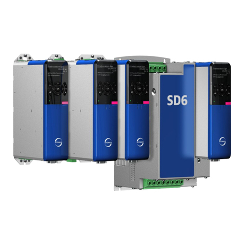
Stober SD6 Series Training manual
Stober
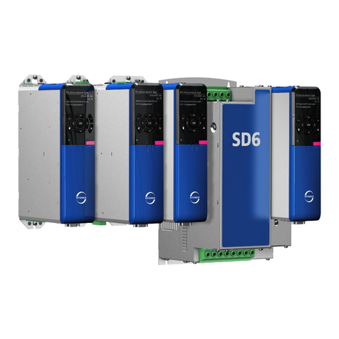
Stober SD6 Series Training manual
Stober
Stober SR6 Training manual
