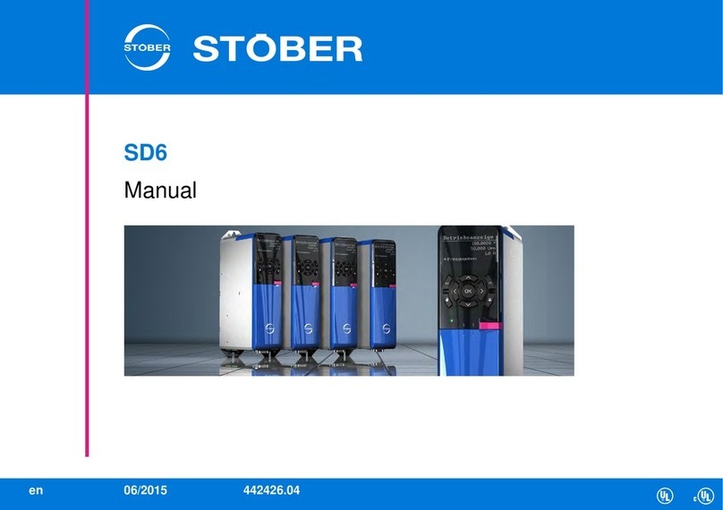
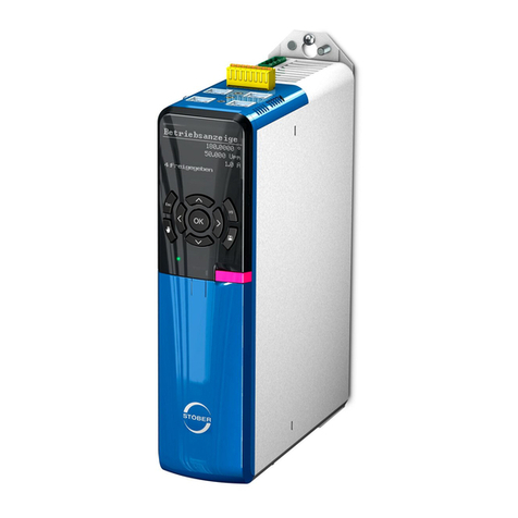
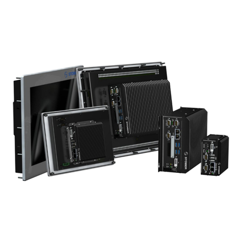
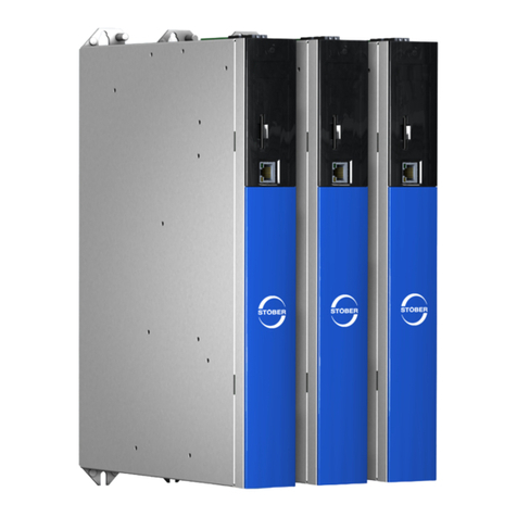
Stober MC6 User manual

MC6
Manual
442461.0307/2015en

ID 442461.03 2WE KEEP THINGS MOVING
Table of contents
Manual MC6
Table of contents
1 General instructions . . . . . . . . . . . . . . . . . . . . . . . . . . . . . . .. . . . .4
1.1 About this manual . . . . . . . . . . . . . . . . . . . . . . . . . . . . . . . . . . . . 4
1.2 Further documentation . . . . . . . . . . . . . . . . . . . . . . . . . . . . . . . . 5
1.3 Further support . . . . . . . . . . . . . . . . . . . . . . . . . . . . . . . . . . . . . . 5
1.4 Directives and norms .. . . . . . . . . . . . . . . . . . . . . . . . . . . . . . . . . 5
1.5 Trademarks . . . . . . . . . . . . . . . . . . . . . . . . . . . . . . . . . . . . . . . . . 6
2 Notes on safety .. . . . . . . . . . . . . . . . . . . . . . . . . . . . . . . . . . .. . . . .7
2.1 Operation in accordance with its intended use . . . . . . . . . . . . . . 7
2.2 Component part of the product . . . . . . . . . . . . . . . . . . . . . . . . . . 7
2.3 Risk assessment . . . . . . . . . . . . . . . . . . . . . . . . . . . . . . . . . . . . . 7
2.4 Qualified personnel . . . . . . . . . . . . . . . . . . . . . . . . . . . . . . . . . . . 7
2.5 System security . . . . . . . . . . . . . . . . . . . . . . . . . . . . . . . . . . . . . . 7
2.6 Disposal .. . . . . . . . . . . . . . . . . . . . . . . . . . . . . . . . . . . . . . . . . . . 8
2.7 Presentation of notes on safety .. . . . . . . . . . . . . . . . . . . . . . . . . 8
3 The Motion Controller MC6 ... . . . . . . . . . . . . . . . . . . . . . .. . . . .9
3.1 Nameplate . . . . . . . . . . . . . . . . . . . . . . . . . . . . . . . . . . . . . . . . . 10
3.2 Type designation . . . . . . . . . . . . . . . . . . . . . . . . . . . . . . . . . . . . 10
3.3 Control and visualization software .. . . . . . . . . . . . . . . . . . . . . . 12
3.3.1 "Motion" software option . . . . . . . . . . . . . . . . . . . . . . 12
3.3.2 "Visualization" software option . . . . . . . . . . . . . . . . . . 13
3.4 Combinable drive controllers . . . . . . . . . . . . . . . . . . . . . . . . . . . 13
3.5 Measures for data security . . . . . . . . . . . . . . . . . . . . . . . . . . . . 13
3.6 Dual-use goods . . . . . . . . . . . . . . . . . . . . . . . . . . . . . . . . . . . . . 15
4 Technical data . . . . . . . . . . . . . . . . . . . . . . . . . . . . . . . . . . . . . . . . .16
4.1 Device features . . . . . . . . . . . . . . . . . . . . . . . . . . . . . . . . . . . . . 16
4.1.1 MC6xx0 Atom Single-Core .. . . . . . . . . . . . . . . . . . . . 16
4.1.2 MC6xx1 Dual-Core Atom . . . . . . . . . . . . . . . . . . . . . . 17
4.1.3 MC6xx5 Core i3 Dual-Core . . . . . . . . . . . . . . . . . . . . 17
4.2 Touch Panel . . . . . . . . . . . . . . . . . . . . . . . . . . . . . . . . . . . . . . . . 18
4.3 Weight . . . . . . . . . . . . . . . . . . . . . . . . . . . . . . . . . . . . . . . . . . . . 18
4.4 Dimensions . . . . . . . . . . . . . . . . . . . . . . . . . . . . . . . . . . . . . . . . 18
4.5 Status display .. . . . . . . . . . . . . . . . . . . . . . . . . . . . . . . . . . . . . . 20
4.6 Transportation, storage and operating environment . . . . . . . . . 20
4.7 Accessories . . . . . . . . . . . . . . . . . . . . . . . . . . . . . . . . . . . . . . . 20
5Installation. . . . . . . . . . . . . . . . . . . . . . . . . . . . . . . . . . . . . . . . . . . .21
5.1 MC6x0 - Control cabinet version . . . . . . . . . . . . . . . . . . . . . . . . 21
5.2 MC6x1 - Install touch panel version .. . . . . . . . . . . . . . . . . . . . . 22
6 Connection . . . . . . . . . . . . . . . . . . . . . . . . . . . . . . . . . . . . . . . . . . . .23
6.1 Overview of terminals . . . . . . . . . . . . . . . . . . . . . . . . . . . . . . . . 23

ID 442461.03 3WE KEEP THINGS MOVING
Table of contents
Manual MC6
6.2 Power supply .. . . . . . . . . . . . . . . . . . . . . . . . . . . . . . . . . . . . . . 24
6.3 Housing ground . . . . . . . . . . . . . . . . . . . . . . . . . . . . . . . . . . . . . 24
6.4 Serial RS-232 . . . . . . . . . . . . . . . . . . . . . . . . . . . . . . . . . . . . . . 24
6.5 CANopen .. . . . . . . . . . . . . . . . . . . . . . . . . . . . . . . . . . . . . . . . . 25
6.6 Ethernet .. . . . . . . . . . . . . . . . . . . . . . . . . . . . . . . . . . . . . . . . . . 25
6.7 DVI . . . . . . . . . . . . . . . . . . . . . . . . . . . . . . . . . . . . . . . . . . . . . . 25
6.8 USB . . . . . . . . . . . . . . . . . . . . . . . . . . . . . . . . . . . . . . . . . . . . . . 25
7 AS6 development environment . . . . . . . . . . . . . . . . . . . . .. . . .26
8 AS6 configuration .. . . . . . . . . . . . . . . . . . . . . . . . . . . . . . . . .. . . .27
8.1 Integrating the MC6 in an AS6 project . . . . . . . . . . . . . . . . . . . 27
8.2 Integrating a drive controller into an AS6 project . . . . . . . . . . . 27
8.2.1 Settings in AS6 .. . . . . . . . . . . . . . . . . . . . . . . . . . . . . 29
8.2.2 Settings in DriveControlSuite . . . . . . . . . . . . . . . . . . . 29
8.3 Check EtherCAT master settings . . . . . . . . . . . . . . . . . . . . . . . 30
8.3.1 The master cycle time is identical . . . . . . . . . . . . . . . 30
8.3.2 Master cycle time is a multiple . . . . . . . . . . . . . . . . . . 30
8.3.3 Principle of operation of the EtherCAT
synchronization . . . . . . . . . . . . . . . . . . . . . . . . . . . . . 31
8.4 Setting up the SoftMotion encoder . . . . . . . . . . . . . . . . . . . . . . 32
8.5 Distributing computer power . . . . . . . . . . . . . . . . . . . . . . . . . . . 32
8.6 Accessing status LEDs . . . . . . . . . . . . . . . . . . . . . . . . . . . . . . . 33
8.7 Triggering an event . . . . . . . . . . . . . . . . . . . . . . . . . . . . . . . . . . 33
8.8 Working with persistent variables . . . . . . . . . . . . . . . . . . . . . . . 34
8.9 Setting up a connection . . . . . . . . . . . . . . . . . . . . . . . . . . . . . . . 35
8.9.1 IP adress and subnet mask . . . . . . . . . . . . . . . . . . . . 35
8.9.2 Network name . . . . . . . . . . . . . . . . . . . . . . . . . . . . . . 36
8.9.3 Remote connection . . . . . . . . . . . . . . . . . . . . . . . . . . 36
8.10 Saving changes . . . . . . . . . . . . . . . . . . . . . . . . . . . . . . . . . . . . . 37
8.11 Changing the resolution of the monitor display . . . . . . . . . . . . . 37
8.12 Installing the OPC server .. . . . . . . . . . . . . . . . . . . . . . . . . . . . . 38
9 Service .. . . . . . . . . . . . . . . . . . . . . . . . . . . . . . . . . . . . . . . . . . . . . . .39
9.1 Memory card . . . . . . . . . . . . . . . . . . . . . . . . . . . . . . . . . . . . . . . 39
9.1.1 Insert memory card in MC6x00 and MC6x01 .. . . . . . 39
9.1.2 Insert memory card in MC6x10 and MC6x11 . . . . . . . 40
9.2 Data backup .. . . . . . . . . . . . . . . . . . . . . . . . . . . . . . . . . . . . . . . 40
9.3 Error messages . . . . . . . . . . . . . . . . . . . . . . . . . . . . . . . . . . . . . 40
9.4 Restart . . . . . . . . . . . . . . . . . . . . . . . . . . . . . . . . . . . . . . . . . . . . 41
10 Maintenance . . . . . . . . . . . . . . . . . . . . . . . . . . . . . . . . . . . . . . . . . .42

ID 442461.03 4WE KEEP THINGS MOVING
General instructions
1
Manual MC6
1 General instructions
Shorter cycle times and a higher level of precision mean ever increasing
requirements for drive technology.
Motion sequences are becoming faster and must be coordinated with each
other with high precision. The controller and drive technology are therefore the
key factors for the increase in productivity and flexibility.
A high-performance Motion Controller is the suitable requirement for a reliable
motion and function sequence for an increasing number of applications, a high
level of functional complexity or even for very demanding applications.
With the development of the MC6 Motion Controller, STOBER can offer
completely independent drive and Motion Control architecture from one
source.
Properties
• CODESYS programming environment for open Motion Control system
concepts
• Suitable for PLC solutions
• For complex interlinked processes with high positioning and adjustment
accuracy
• Track travel with the interpolation of several axes and robot functions
• Available as a switch cabinet PC or in combination with a touch panel
1.1 About this manual
This manual describes the Motion Controller MC6. It includes relevant
information on connections and installation as well as commissioning.
This manual is intended for specialists who are familiar with PLC and
CODESYS programming.
This documentation applies to the following devices:
• Motion Controller MC6 versions A, B or C as well as
hardware version 0, 1 or 5
• CODESYS programming system version 3.5 or higher
Original version
The original version of this manual is in German.
What is new?
ID Index Date Changes
442461 00 04/2013 First edition
01 07/2013 General corrections
02 10/2014 • General corrections
• Additions
• Version B
• EtherCAT master settings
03 06/2015 • General corrections
• Additions
• Hardware version 1 with Dual Core
Atom
• Hardware version 5 with Core i3
Dual Core

ID 442461.03 5WE KEEP THINGS MOVING
General instructions
1
Manual MC6
1.2 Further documentation
The documentation listed in the following table provides relevant information on
the SD6 drive controller.
You can find the latest document versions at www.stoeber.de.
1.3 Further support
If you have technical questions that are not answered by this document, please
contact:
• Phone: +49 7231 582-3060
• E-mail: applications@stoeber.de
If you have questions about the documentation, please contact:
• E-mail: electronics@stoeber.de
If you have questions about training sessions, please contact:
• E-mail: training@stoeber.de
1.4 Directives and norms
The MC6 Motion Controller meets the requirements of the following directives
and standards:
• Low Voltage Directive 2006/95/EC
• EMC Directive 2004/108/EC
You can obtain the Declaration of Conformity upon request from
electronics@stoeber.de.
Device/Software Documentation Contents ID
SD6 drive controllers Manual System
environment,
technical data,
commissioning,
communication,
diagnosis
442426
EtherCAT EC6
communication module
Manual Technical data,
installation,
commissioning, data
transfer
442516
CANopen CA6
communication module
Manual Technical data,
installation,
commissioning, data
transfer
442637

ID 442461.03 6WE KEEP THINGS MOVING
General instructions
1
Manual MC6
1.5 Trademarks
The following names that are used in conjunction with the device, its optional
equipment and its accessories are trademarks or registered trademarks of
other companies:
All other trademarks that are not listed here are the property of their respective
owners.
Products that are registered as trademarks are not specially indicated in this
documentation. Existing property rights (patents, trademarks, protection of
utility models) are to be observed.
Trademarks
CANopen,
CiA
CANopen and CiA are registered Community trademarks
of CAN in Automation e.V., Nuremberg, Germany.
CODESYS CODESYS is a registered trademark of 3S-Smart
Software Solutions GmbH, Kempten, Germany.
EtherCAT EtherCAT and the EtherCAT logo are registered
trademarks of Beckhoff Automation GmbH, Verl,
Germany.
Intel,
Intel Atom,
Intel Core
Intel, the Intel logo, Intel Atom and Intel Core are
registered trademarks of Intel Corporation or its
subsidiaries in the USA or other countries.
Microsoft,
Windows,
Windows XP,
WIndows 7
Microsoft, Windows, Windows XP and the Windows logo
are registered trademarks of Microsoft Corporation in the
USA and/or other countries.
PROFIBUS,
PROFINET
The PROFIBUS/PROFINET logo is a registered
trademark of PROFIBUS Nutzerorganisation e. V.
Karlsruhe, Germany.

ID 442461.03 7WE KEEP THINGS MOVING
Notes on safety
2
Manual MC6
2 Notes on safety
2.1 Operation in accordance with its intended
use
The Motion Controller MC6 is intended exclusively for automation in industrial
systems for use within the general conditions defined by the technical data.
Other applications are not permitted.
2.2 Component part of the product
The technical documentation is a component part of a product.
• Since the technical documentation contains important information, always
keep it handy in the vicinity of the device until the machine is disposed of.
• If the product is sold, disposed of, or rented out, always include the
technical documentation with the product.
2.3 Risk assessment
Before the manufacturer may bring a machine onto the market, he must
conduct a risk assessment according to Machine Directive 06/42/EC. As a
result, the risks associated with the use of the machine are determined. The
risk assessment is a multi-stage and iterative process. On no account can
sufficient insight into the Machine Directive be given as part of this
documentation. For this reason, seek detailed information about the norms and
legal position. When installing the drive controller in machines, commissioning
is forbidden until it has been determined that the machine meets the
requirements of EC Directive 06/42/EC.
2.4 Qualified personnel
Devices may cause residual risks. For this reason, all work on the devices as
well as operation and disposal must only be performed by qualified personnel
who are aware of the possible dangers.
Qualified personnel are persons who have acquired the authorisation to
perform these activities by
• Training from specialists and/or
• Instruction from specialists
In addition, they must have
• read,
• understood and
• observed the applicable regulations, legal provisions, rules and standards
and existing technical documentation including the safety information
contained in it.
2.5 System security
If the MC6 is connected with network access to the Internet, STOBER
recommends placing an industrial firewall in between. It is also advisable to
perform remote maintenance processes only via a secured VPN network. Anti-
virus software is not recommended on the MC6 in this situation, as it may affect
the real-time response in some circumstances.

ID 442461.03 8WE KEEP THINGS MOVING
Notes on safety
2
Manual MC6
2.6 Disposal
Please observe the current national and regional regulations! Dispose of the
individual parts separately depending on the quality and currently applicable
regulations, e.g. as
• Electronic waste (circuit boards)
• Plastic
• Sheet metal
• Copper
•Aluminum
•Battery
2.7 Presentation of notes on safety
NOTICE
Notice
means that property damage may occur
if the stated precautionary measures are not taken.
CAUTION!
Caution
with warning triangle means that minor injury may occur
if the stated precautionary measures are not taken.
WARNING!
Warning
means that there may be a serious danger of death
if the stated precautionary measures are not taken.
DANGER!
Danger
means that serious danger of death exists
if the stated precautionary measures are not taken.
Information
refers to important information about the product or serves to
emphasize a section in the documentation to which the reader
should pay special attention.

ID 442461.03 9WE KEEP THINGS MOVING
The Motion Controller MC6 ...
3
Manual MC6
3 The Motion Controller MC6 ...
The Motion Controller MC6 is the ideal requirement for a reliable, coordinated
motion and function sequence for an increasing number of applications, a high
level of functional complexity or even for very demanding applications.
The following figure shows one of the possible system environments for the
interaction of the MC6 and the SD6 drive controller.
Note that a SD6 drive controller can only be connected as a SoftMotion axis via
EtherCAT with the MC6.

ID 442461.03 10WE KEEP THINGS MOVING
The Motion Controller MC6 ...
3
Manual MC6
3.1 Nameplate 3.2 Type designation
Sample code
Explanation
Designation Value in the example Meaning
TYPE MC6B00CN Device type according to
type key
KT.NO. 56524 Purchased part number
S/N 8732562 Serial number
Input power supply 9–32 VDC
Power consumption max. 12 watts Power consumption
Protection class IP20
CODESYS V3.5 SP5 Version of the software in
memory at the time of
delivery
MC 6 A 0 0 C T
Code Designation Design
MC Series Motion Control
6Generation 6th generation
A, B, C Software version Version of the image
0Design As control cabinet PC
1 With touch panel
0...9 Hardware version 0: Atom Single-Core
1: Dual-Core Atom
5: Core i3 Dual-Core
N "Motion" software option Control
S SoftMotion
CSoftMotion CNC
N "Visualization" software option Without
TTarget visualization
W Web visualization
A Target visualization and web
visualization

ID 442461.03 11WE KEEP THINGS MOVING
The Motion Controller MC6 ...
3
Manual MC6
Versions
The following MC6 versions are currently available.
If you require other versions that are not included in the list but correspond to
the type key, please contact the sales team of STÖBER ANTRIEBSTECHNIK
GmbH & Co. KG:
Fon: + 49 7231 582-1165 Fax: + 49 7231 582-4165sales@stoeber.de
Type KT-No. Description
MC6A00CN 56444 MC6 Motion Controller with software option 3.5:
SoftMotion CNC (without visualization)
(Application: only for service purposes)
MC6A00CT 56445 MC6 Motion Controller with the software options:
• SoftMotion CNC
• Target visualization
(Application: only for service purposes)
MC6A10CT 56446 MC6 Motion Controller with 15" touch panel and
software options:
• SoftMotion CNC
• Target visualization
(Application: only for service purposes)
MC6B00CN 56524 MC6 Motion Controller with software option 3.5.5.0:
SoftMotion CNC (without visualization)
MC6B00CT 56525 MC6 Motion Controller with the software options
3.5.5.0:
• SoftMotion CNC
• Target visualization
MC6C10CT 56526 MC6 Motion Controller with 15" touch panel and
software options 3.5.5.0:
• SoftMotion CNC
• Target visualization
MC6B00NT 56527 MC6 Motion Controller with the software options
3.5.5.0:
• CODESYS Control
• Target visualization
MC6C01CT 56564 MC6 Motion Controller Dual Core with the software
options 3.5.6.40:
• SoftMotion CNC
• Target visualization
MC6C11CT 56565 MC6 Motion Controller Dual Core with the software
options 3.5.6.40:
• SoftMotion CNC
• Target visualization
MC6C05CA 56566 MC6 Motion Controller Core i3 with the software
options 3.5.6.40:
• SoftMotion CNC
• Target and web visualization
MC6C15CA 56567 MC6 Motion Controller Core i3 with touch panel and
software options 3.5.6.40:
• SoftMotion CNC
• Target and web visualization
Type KT-No. Description

ID 442461.03 12WE KEEP THINGS MOVING
The Motion Controller MC6 ...
3
Manual MC6
3.3 Control and visualization software
3.3.1 "Motion" software option
Three versions of the "Motion" controller software are available with different
functionalities.
"Control (N)" license
The Control license (key "N") is a basic license that is included in the scope of
delivery as standard.
"Control" enables flexible programming according to IEC 61131-3 and supports
the following languages:
• Structured text (ST)
• Sequential language (AS, SFC)
• Graphical function plan (CFC)
• Function plan diagram (FUP)
• Contact plan (KOP)
• Instruction list (AWL)
"SoftMotion (S)" license
The SoftMotion license (key "S") is based on the Control license and also
enables motion programming with PLCopen-compliant modules.
The integrated disk cam editor can either be used online in the target system
or offline in the programming system.
Cams can be directly connected to cam disks. In addition any number of
couplings is possible between virtual and real axes using a cam disk or
electronic gear units. This license also supports a cam disk change on the fly.
Cam data can be an integral part of the project.
"SoftMotion CNC (C)" license
The SoftMotion CNC license (key "C") is based on the SoftMotion license and
also enables numerous coordinate transformations for commonly used
mechanical processes, for example:
• 6 different Gantry drives
• H portal (wrap-around belt)
• T portal (wrap-around belt)
• SCARA drive, 2 articulation points
• SCARA drive, 3 articulation points
• Bipod drive
• 2 different tripods
• 5-axis pelletizing robot
• 6-axis articulated robot
The creation of your own transformations is also supported.
The SoftMotion CNC license also makes a 3D CNC editor as defined by DIN
66025 (G code, dynamic) available. Cam and CNC data can be an integral part
of the project. The PLC program can influence the CNC trajectory dynamically
at runtime.
You also have the option to transfer CNC data from 3D design programs.
Furthermore, complex 3D trajectories can be created independently by the
mechanics.

ID 442461.03 13WE KEEP THINGS MOVING
The Motion Controller MC6 ...
3
Manual MC6
3.3.2 "Visualization" software option
The connection of graphic user interfaces is possible using the "Visu"
visualization software. Two versions of the software are available with different
functionalities.
"Target visualization (T)" license
The target visualization license (key "T") supports the visualization options of
the target system. The license offers a large selection of predefined
visualization elements. For example, they generate control masks in the
visualization editor or complete control masks can be reused as individual
visualization elements.
Complex visualization elements can be instantiated by an interface for the
parameter transfer. Visualization is possible using an integrated editor for text
lists in multiple languages.
"Web visualization (W)" license
The web visualization license (key "W") supports the same visualization
options as the target visualization license. However access does not occur via
a visualization of the target system but via the network by means of HTML5
from a network-compatible panel, PC or tablet.
"Target visualization and web visualization (A)" license
This license (key "A") combines both the target visualization and web
visualization licenses.
3.4 Combinable drive controllers
You can operate the following STOBER devices in combination with the MC6
controller:
• 5th generation devices: SDS 5000, MDS 5000, FDS 5000
• SD6 drive controllers
Please note that no axis switching can be used on these devices during
operation with the MC6.
Currently the interaction of MC6 and SD6 with the "SoftMotion" and
"SoftMotion CNC" software options is possible.
If you require a different type of license, please contact us.
3.5 Measures for data security
Control systems are frequently used in areas where an orderly shutdown or
switching off is not possible.
Especially if control systems are based on PC technology and use a standard
operating system, this involves the risk that the file system will be damaged.
The only reliable method for protecting a Windows file system is to use an
uninterruptible power supply (UPS). These systems supply the current
required for shutdown if the power supply fails. These systems also inform the
operating system via a potential input or a serial interface so that shutdown can
be initiated immediately.
The disadvantages of this hardware solution include higher costs for the
additional hardware. UPS systems also usually store energy in containers with
several batteries that have only a limited service life, which unavoidably leads
to higher maintenance overhead.
Solutions based entirely on software are unable to prevent the file system from
being damaged if the current is shut off. However suitable measures reduce the
frequency of occurrence or enable a repair. Furthermore there are no expenses
for additional hardware and maintenance.

ID 442461.03 14WE KEEP THINGS MOVING
The Motion Controller MC6 ...
3
Manual MC6
Measures are described below that can be taken with systems from STOBER
to increase the security of the file system and data in them for the event of a
power failure.
First shut down the system, then turn it off
If the MC6 is shut off while the software is writing a file to the Solid State Drive
(SSD) or CFast storage media, the file will be damaged in most cases.
Control software generally describes these storage media independently in
intervals of a few seconds. Because of this, the probability of causing damage
due to shutdown when the software is running is very high. However various
measures have been taken to minimize the occurrence of these conditions.
EWF Manager
The standard measure for protecting an application in an NTFS-based
Windows file system is the Enhanced Write Filter (EWF), which is included with
delivery of the embedded versions of Windows operating systems.
When EWF is activated, the operating system stores the data for the file
system in main memory during the boot process, thereby preventing the data
storage media from being written to directly.
Therefore if the voltage supply fails, only the data in main memory is affected.
In contrast, damage to the file system on the data storage media is prevented.
The EWF protects the entire partition, but at the same time prevents data from
being stored persistently on it. It does appear that data is being saved.
However, the data is located in main memory after the process is complete, not
on the storage medium! To write the data on the storage medium, the EWF
must first be deactivated and the system restarted. This means that it is
impossible to save data while the PLC is running without losing the protection
of the file system that is desired.
However, parts of the CODESYS runtime environment that are not variable
(software, licenses, configurations) can be protected by the EWF filter.
Several partitions have been set up on the MC6 for this purpose. One of them
contains the operating system and the non-variable elements of the CODESYS
runtime environment. This partition is protected by the EWF. Other partitions
are enabled for writing and are then used to store the boot project and if
necessary data that is generated by the PLC application.
This procedure can be used to ensure that the partition with the operating
system and CODESYS environment remains undamaged. It also makes it
possible to store variable data as well.
File system check
The CODESYS runtime environment on the MC6 is not started by the
conventional autostart mechanism of the operating system. Instead a batch
script is used for starting. The last command of this script initiates the start of
the runtime environment.
This is not a measure that contributes directly to improving the security of the
file system. However, it does make it possible to run checks before the start of
the runtime environment, so that possible damage to the file system can be
detected and countermeasures can be introduced.
Before the CODESYS runtime environment starts, the consistency of the file
system is checked automatically after a system starts up. This is done in
ReadOnly mode, which makes it possible to reduce the time required for the
check to a minimum.
If the file system is damaged, a repair is initiated automatically. The system
must leave ReadOnly mode to do this, but the required measure takes only a
few seconds. It is only started in the event that damage has occurred and
further contributes to increasing data security by automatically eliminating
minor defects.

ID 442461.03 15WE KEEP THINGS MOVING
The Motion Controller MC6 ...
3
Manual MC6
3.6 Dual-use goods
From version B, the CNC variant does not require approval for export. Note that
the no more than 4 axes can be interpolated together at the same time at a
interpolator with the export version that does not require approval.
Information
Note that version A of the MC6 in the CNC variant (for example
MC6A10CT) requires approval for export outside the EU in
accordance with item 2D002 of the List of Dual-Use Goods 1 cat. 2
(for example as a replacement part). You can obtain information
about the approval process from the responsible office (in Germany
the Federal Office for Economics and Export Control).
If the MC6 is installed in a machine in the CNC variant,
categorization as a machine applies for the approval process.

ID 442461.03 16WE KEEP THINGS MOVING
Technical data
4
Manual MC6
4 Technical data
4.1 Device features
4.1.1 MC6xx0 Atom Single-Core
Processor • Intel Atom Processor Z530, 1.6 GHz
• Front Side Bus, 533 MHz
• L2 Cache, 512 kB
Memory • DDR2-RAM, 1 GB
• Internal SSD with 4 GB
• 128 kB nvSRAM (no battery backup necessary)
• Internal CFast socket for SATA-based SSD modules
Voltage
supply
• MC6x00: 9 – 32 VDC
• MC6x10: 14 – 32 VDC
Power
consumption
•MC6x00:max.12W
• MC6x10: max. 25 W
Front
connections
• Realtek RTL8111 Ethernet controller,
10/100/1000 Mbit/s
• Single Chip fast Ethernet NIC controller, 10/100 Mbit/s
• 3 x USB 2.0 interfaces, type A, 480 Mbit/s,
with 500 mA current carrying capacity per output
• Reset button and power LED
• Serial RS-232 interface (RTS/CTS only): D-sub
connector, 9-pin
• CANopen interface: D-sub connector, 9-pin
• 2 freely programmable front panel LEDs
Protection
class
•IP20
Other • CODESYS IEC61131-3 runtime for SoftMotion CNC
environment (note the functional differences between
the software licenses)
• Windows XP Embedded operating system
• Battery-supported real-time clock (internal watchdog)

ID 442461.03 17WE KEEP THINGS MOVING
Technical data
4
Manual MC6
4.1.2 MC6xx1 Dual-Core Atom 4.1.3 MC6xx5 Core i3 Dual-Core
Processor • Intel Atom Dual-Core E3825, 2x 1.33 GHz
• L2 Cache, 1 MB
Memory • DDR3-RAM, 2 GB
• 128 kB nvRAM (no battery backup necessary)
• CFast card, 8 GB
Voltage
supply
• MC6x01: 9 – 32 VDC
• MC6x11: 14 – 32 VDC
Power
consumption
•MC6x01:max.10W
• MC6x11: max. 23 W
Front
connections
• Realtek RTL8111 Ethernet controller,
10/100/1000 Mbit/s
• Single Chip fast Ethernet DM9102D controller, 10/100
Mbit/s
• 3 x USB 2.0 interfaces, type A, 480 Mbit/s,
with 500 mA current carrying capacity per output
• Reset button and power LED
• Serial RS-232 interface (RTS/CTS only): D-sub
connector, 9-pin
• CANopen interface: D-sub connector, 9-pin
• 2 freely programmable front panel LEDs
Protection
class
•IP20
Other • CODESYS IEC61131-3 runtime for SoftMotion CNC
environment (note the functional differences between
the software licenses)
• Windows 7 Embedded operating system
• Battery-supported real-time clock (internal watchdog)
Processor • Intel Core i3-3120ME, 2x 2.4 GHz
• L2 Cache, 3 MB
Memory • DDR3-RAM, 2 GB
• 128 kB MRAM (no battery backup necessary)
• CFast card, 8 GB
Voltage
supply
• MC6x05: 9 – 32 VDC
• MC6x15: 14 – 32 VDC
Power
consumption
• MC6x05: on request
• MC6x15: on request
Front
connections
• 2x Realtek RTL8111 Ethernet controllers,
10/100/1000 Mbit/s
• 4 USB 3.0 interfaces, type A, 480 Mbit/s,
with 500 mA current carrying capacity per output
• Reset button and power LED
• Serial RS-232 interface (RTS/CTS only): D-sub
connector, 9-pin or CANopen DVI monitor connection
Protection
class
•IP20
Other • CODESYS IEC61131-3 runtime for SoftMotion CNC
environment (note the functional differences between
the software licenses)
• Windows 7 Embedded operating system
• Battery-supported real-time clock (internal watchdog)

ID 442461.03 18WE KEEP THINGS MOVING
Technical data
4
Manual MC6
4.2 Touch Panel
The following features also apply for the version with touch panel:
4.3 Weight
The following table includes the total weight of the individual MC6 versions.
4.4 Dimensions
Display • 15.0" (38.1 cm) XGA TFT LCD
• CCFL backlight
• Pixel pitch 0.297 0.297
• Display mode: normal white
• Resolution 1,024 768
• 16.7 million colors
• Contrast rate 700:1 (typical), at least 480:1
• Brightness 450 cd/m2(typical)
• Viewing angle horizontal 160°, vertical 160°
• MTBF 50,000 h
Touch screen • Resistive 4-line touch screen
• Protection class IP65
Type Total weight (kg)
MC6x00 0.8
MC6x01 0.8
MC6x05 1.95
MC6x10 4.8
MC6x11 4.8
MC6x15 5.95
Type Height (mm) Width (mm) Depth (mm)
MC6x00, MC6x01 111 66 112
MC6x05 171 230 96
MC6x10, MC6x11 306 382 100
MC6x15 306 382 128

ID 442461.03 19WE KEEP THINGS MOVING
Technical data
4
Manual MC6
MC6x00 and MC6x01
MC6x10 and MC6x11
MC6x05
MC6x15

ID 442461.03 20WE KEEP THINGS MOVING
Technical data
4
Manual MC6
4.5 Status display
The MC6 has three status LEDs with different functions.
• LED Power: displays the voltage supply.
•LEDs S0 and S1: display the CANopen status or visualize the individual
program states (see section 8.6 Accessing status LEDs).
4.6 Transportation, storage and operating
environment
DANGER!
Explosion hazard!
The device could ignite a potentially explosive atmosphere in an area subject
to explosion hazard.
Do not operate the device in an area subject to explosion hazard.
WARNING!
Fire hazard!
This product does not meet the requirements for a fire cover in accordance with
DIN EN 60950-1 in all possible installation positions.
The device may only be installed above non-flammable materials.
CAUTION!
Device damage!
Overheating inside the device will lead to device damage.
Operate the device within the specified operating conditions.
Ensure that the ventilation openings are not covered.
4.7 Accessories
CFast memory cards can be installed as an option.
Type MC6xx0 MC6xx1, MC6xx5
Operating temperature 0 – 50 °C 0 – 45 °C
Storage temperature -20 – 75 °C
Relative humidity 0 – 80 %, non condensing
Other manuals for MC6
1
Table of contents
Other Stober Controllers manuals

Stober
Stober SD6 Series User manual

Stober
Stober SD6 Series Training manual

Stober
Stober MC6 User manual

Stober
Stober SC6 Series Training manual

Stober
Stober SC6 Series Training manual

Stober
Stober SD6 Series User manual

Stober
Stober SD6 Series User manual

Stober
Stober SR6 Training manual

Stober
Stober CiA 402 User manual

Stober
Stober SC6 Series User manual