Stoelting CF101 User manual

Model CF101
OPERATORS MANUAL
Manual No. 513624 Rev.3


This manual provides basic information about the machine. Instructions and suggestions are
given covering its operation and care.
The illustrations and specifications are not binding in detail. We reserve the right to make
changes to the machine without notice, and without incurring any obligation to modify or pro-
vide new parts for machines built prior to date of change.
DO NOTATTEMPT to operate the machine until instructions and safety precautions in this
manual are read completely and are thoroughly understood. If problems develop or questions
arise in connection with installation, operation, or servicing of the machine, contact Stoelting.
Stoelting Foodservice Equipment
502 Highway 67
Kiel, WI 53042-1600
U.S.A.
Main Tel: 800.558.5807
Fax: 920.894.7029
Customer Service: 888.429.5920
Fax: 800.545.0662
© 2014 PW Stoelting, LLC
stoeltingfoodservice.com

Safety Alert Symbol:
This symbol Indicates danger, warning or caution.
Attention is required in order to avoid serious per-
sonal injury. The message that follows the symbol
contains important information about safety.
Signal Word:
Signal words are distinctive words used throughout
this manual that alert the reader to the existence and
relative degree of a hazard.
CAUTION
The signal word “CAUTION” indicates a potentially
hazardous situation, which, if not avoided, may result
in minor or moderate injury and equipment/property
damage.
A Few Words About Safety
Safety Information
Read and understand the entire manual before
operating or maintaining Stoelting equipment.
This manual provides the operator with information
for the safe operation and maintenance of Stoelting
equipment. As with any machine, there are hazards
associated with their operation. For this reason safety
is emphasized throughout the manual. To highlight
specific safety information, the following safety defini-
tions are provided to assist the reader.
The purpose of safety symbols is to attract your at-
tention to possible dangers. The safety symbols, and
their explanations, deserve your careful attention
and understanding. The safety warnings do not by
themselves eliminate any danger. The instructions
or warnings they give are not substitutes for proper
accident prevention measures.
If you need to replace a part, use genuine Stoelting
parts with the correct part number or an equivalent
part. We strongly recommend that you do not use
replacement parts of inferior quality.
WARNING
The signal word “WARNING” indicates a potentially
hazardous situation, which, if not avoided, may result
in death or serious injury and equipment/property
damage.
CAUTION
The signal word “CAUTION” not preceded by the
safety alert symbol indicates a potentially hazardous
situation, which, if not avoided, may result in equip-
ment/property damage.
NOTE (or NOTICE)
The signal word “NOTICE” indicates information or
procedures that relate directly or indirectly to the
safety of personnel or equipment/property.

Section Description Page
1 Description and Specifications
1.1 Description .................................................................................................1
1.2 Specifications.............................................................................................2
2 InstallationInstructions
2.1 SafetyPrecautions .....................................................................................3
2.2 ShipmentandTransit .................................................................................3
2.3 MachineInstallation....................................................................................3
3 Initial Set-Up and Operation
3.1 Operator’sSafetyPrecautions....................................................................5
3.2 OperatingControlsandIndicators...............................................................5
3.3 Sanitizing ...................................................................................................6
3.4 FreezeDownandOperation .......................................................................7
3.5 MixInformation...........................................................................................8
3.6 RemovingMixfromMachine.......................................................................8
3.7 CleaningtheMachine .................................................................................8
3.8 Disassembly of Machine Parts ...................................................................8
3.9 CleaningtheMachineParts........................................................................9
3.10 Assembly of Machine .................................................................................9
3.11 RoutineCleaning ........................................................................................10
3.12 PreventativeMaintenance ...........................................................................10
3.13 ExtendedStorage.......................................................................................12
4 Troubleshooting
4.1 ErrorCodes ................................................................................................13
4.2 TroubleshootingErrorCodes ......................................................................13
4.3 TroubleshootingTables...............................................................................15
5 Replacement Parts
5.1 DecalsandLubrication ...............................................................................17
5.2 AugerShaftandFaceplateParts................................................................18
5.3 HopperParts ..............................................................................................19
TABLE OF
CONTENTS


1
1.1 DESCRIPTION
The CF101 is a counter top continuous flow custard
machine. It is equipped with fully automatic controls to
provide a uniform product and features Quick-Freeze
technology. This manual is designed to assist qualified
servicepersonnelandoperatorsintheinstallation,opera-
tion and maintenance of the CF101 frozen custard ma-
chine. NOTE
The freezing cylinder of the CF101 is not intended
to store product for more than one hour.
SECTION 1
DESCRIPTION AND SPECIFICATIONS
Figure 1-2 CF101 Specifications

2
1.1 SPECIFICATIONS
Dimensions
width
height
depth
Weight
Electrical
running amps
connectiontype
Compressor
Drive Motor
Air Flow
Hopper Volume
Freezing Cylinder
Volume
CF101
Machine with crate
19-1/2'' (49,5 cm) 38-3/4'' (98,4 cm)
310 lbs (140,6 kg) 380 lbs (172,3 kg)
1 Phase,208-240 VAC, 60Hz
37-3/4'' (95,9 cm) 28-3/4'' (73,0 cm)
28'' (71,1 cm) 43'' (109,2 cm)
approximately15A
NEMA6-20P power cord provided
Air cooled units require 6" (15,2 cm)air space at left and right sides and 10"
(25,4) air space above the machine.
0.8 gallon(3.2 quart),3,03 liters
5.4 gallon(30,28 liters)
14,000 Btu/hr
1-1/2 hp

3
SECTION 2
INSTALLATION INSTRUCTIONS
2.1SAFETYPRECAUTIONS
Do not attempt to operate the machine until the safety
precautions and operating instructions in this manual are
read completely and are thoroughly understood.
Takenoticeofallwarninglabelsonthemachine.Thelabels
have been put there to help maintain a safe working
environment.Thelabelshavebeendesignedtowithstand
washing and cleaning. All labels must remain legible for
thelifeofthemachine.Labelsshouldbecheckedperiodi-
callytobesuretheycanberecognizedaswarninglabels.
If danger, warning or caution labels are needed, indicate
the part number, type of label, location of label, and
quantityrequired along with your addressand mail to:
STOELTING
ATTENTION: Customer Service
502 Hwy. 67
Kiel, Wisconsin 53042
2.2 SHIPMENT AND TRANSIT
Themachinehasbeenassembled,operatedandinspected
at the factory. Upon arrival at the final destination, the
entire machine must be checked for any damage which
mayhaveoccurredduringtransit.
With the method of packaging used, the machine should
arriveinexcellentcondition.THECARRIERISRESPON-
SIBLE FOR ALL DAMAGE IN TRANSIT, WHETHER
VISIBLEORCONCEALED.Donotpaythefreightbilluntil
the machine has been checked for damage. Have the
carrier note any visible damage on the freight bill. If
concealeddamageand/orshortageisfound later, advise
the carrier within 10 days and request inspection. The
customermustplaceclaimfordamagesand/orshortages
in shipment with the carrier. Stoelting, Inc. cannot make
any claims against the carrier.
2.3MACHINEINSTALLATION
Installation of the machine involves moving the machine
close to its permanent location, removing all crating,
setting in place, assembling parts, and cleaning.
A. Uncratethemachine.
B. Accuratelevelingisnecessaryforcorrectdrainage
of machine barrel and to insure correct overrun.
Placeabubblelevelontopofthemachineateach
corner to check for level condition. If adjustment
is necessary, level the machine by turning the
bottom part of each leg in or out. Then separate
machinebasegasketandinstallwithseamtothe
back and angle to the top.
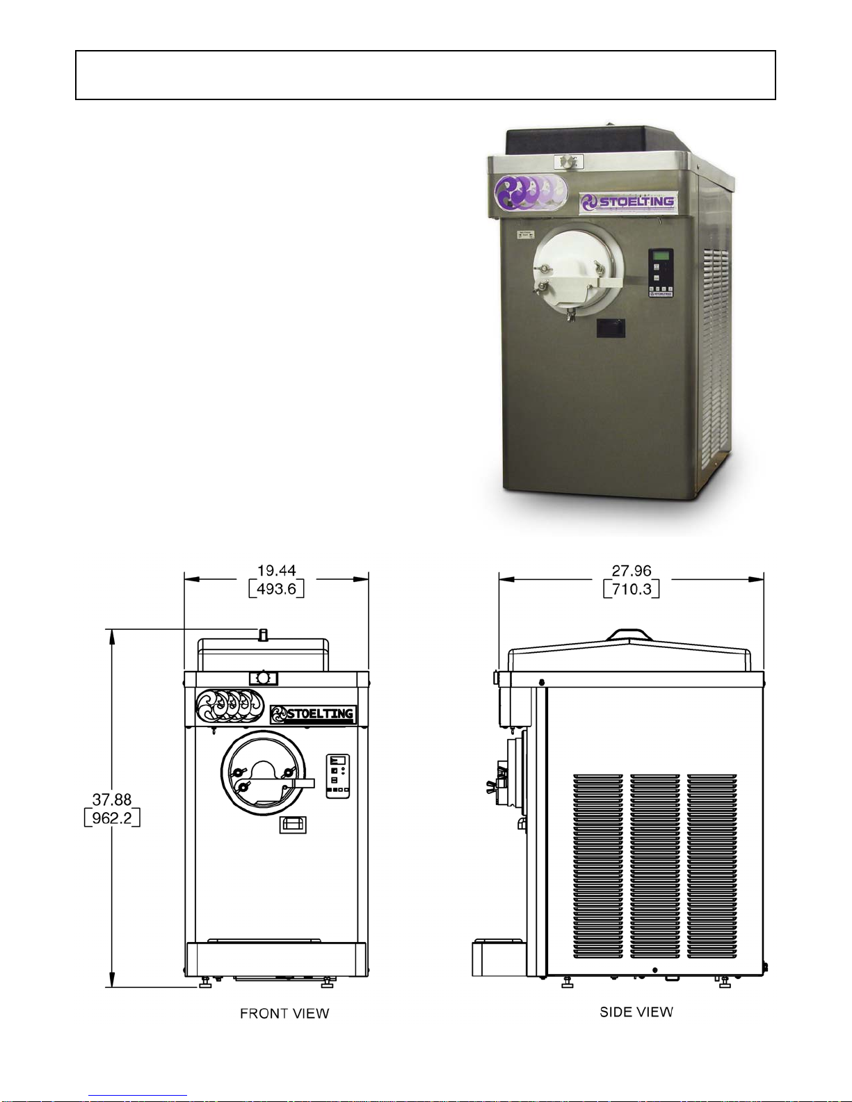
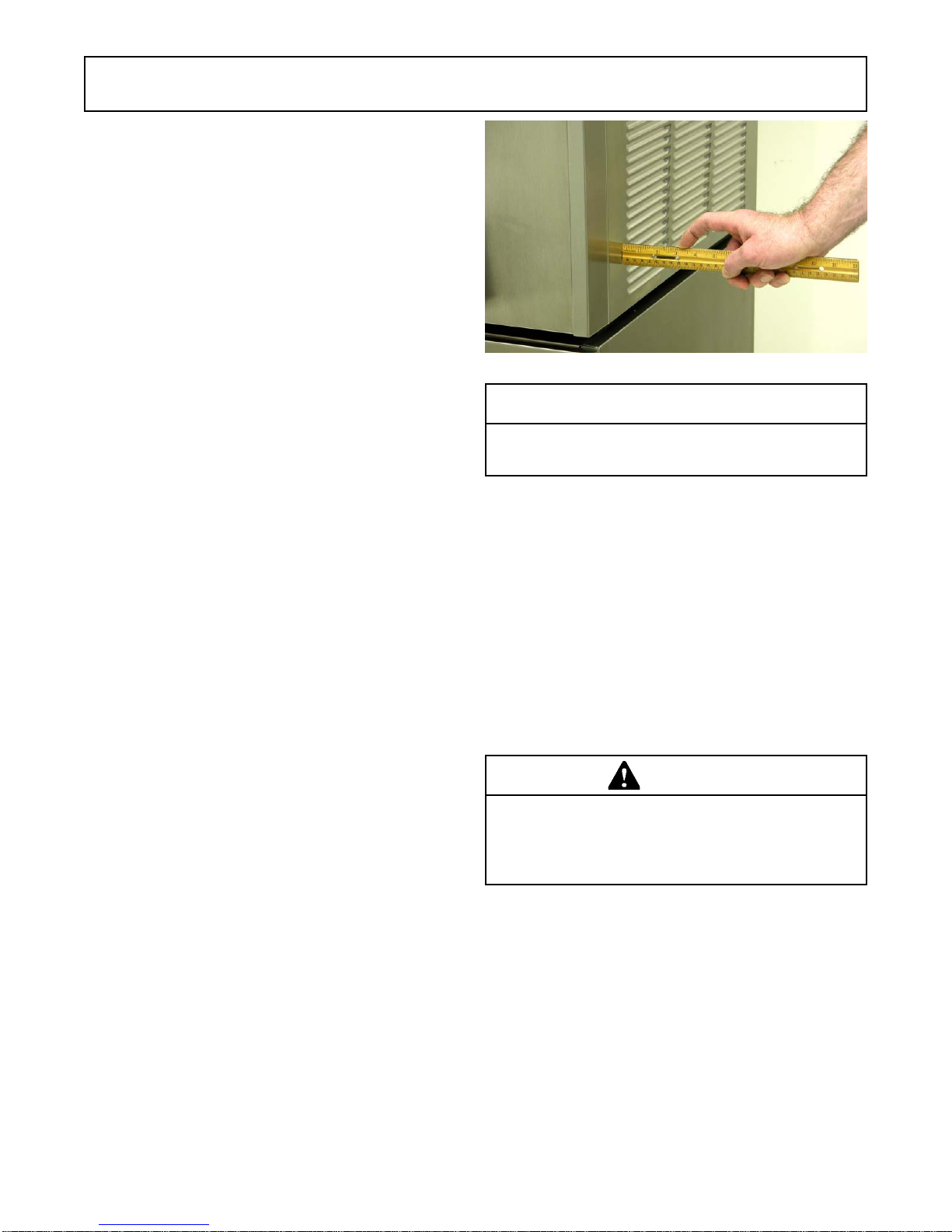
C. Correctventilationisrequired.TheCF101requires
a minimum of 6" (15,2 cm) air space at left and
right sides and 10" (25,4) air space above the
machine.
CAUTION
Failuretoprovide adequate ventilationwillvoid war-
ranty.
D. Place the Main Freezer Power Off/On switch in
the OFF position.
E. Connect the power cord to the proper power
supply. The plug is designed for 208-240 volt/20
ampduty.Checkthenameplateonyourmachine
for proper supply. The unit must be connected to
a properly grounded receptacle. The electrical
cordfurnishedaspartofthemachinehasa three
pronggroundingtypeplug.Theuseofanextension
cord is not recommended, if necessary use one
witha size 12gauge orheavier withground wire.
Do not use an adapter to get around grounding
requirement.
WARNING
Do not alter or deform electrical plug in any way.
Altering the plug to fit into an outlet of different con-
figuration may cause fire, risk of electrical shock,
product damage and will void warranty.
Figure 2-2 Space and Ventilation Requirements

4

5
SECTION 3
INITIAL SET-UP AND OPERATION
3.1 OPERATOR’S SAFETY PRECAUTIONS
SAFE OPERATION IS NO ACCIDENT; observe these
rules:
A. Know the machine. Read and understand the
OperatingInstructions.
B. Notice all warning labels on the machine.
C. Wearproperclothing.Avoidloosefittinggarments,
and remove watches, rings or jewelry that could
cause a serious accident.
D. Maintain a clean work area. Avoid accidents by
cleaning up the area and keeping it clean.
E. Stay alert at all times. Know which switch, push
button or control you are about to use and what
effect it is going to have.
F. Disconnectelectricalcordformaintenance.Never
attempt to repair or perform maintenance on the
machineuntilthemainelectricalpowerhasbeen
disconnected.
G. Donotoperateunderunsafeoperatingconditions.
Neveroperatethemachineifunusualorexcessive
noise or vibration occurs.
3.2 OPERATING CONTROLS AND
INDICATORS
Before operating the machine, it is required that the
operatorknowthefunctionofeachoperatingcontrol.Refer
toFigure3-1forthelocationoftheoperatingcontrolsonthe
machine.
WARNING
High voltage will shock, burn or cause death. The
OFF-ONswitch mustbe placedin theOFF position
prior to disassembling for cleaning or servicing. Do
not operate machine with cabinet panels removed.
A. Main Freezer Power OFF-ON Switch
TheMainFreezerPowerOFF-ONswitchisatwo-
positiontoggleswitchusedtosupplypowertothe
control circuit. When the switch is in the OFF
position, power will not be supplied to the control
boardorrefrigerationsystem.Whentheswitchis
put in the ON position, the machine will be in
standbymode.ThedisplaywillreadStandbyand
the amber LED will light.
Figure 3-1 Machine Controls
IntelliTec Control
(See Figure 3-2)
Main Freezer
Power Off/On
Product
Selector
Switch

6
B. Product Selector Switch
The product selector switch changes the
refrigerationprofiletoallowtwodifferentproducts
tobemade.Beforethemachineisinreadymode,
this switch can be moved to the desired profile.
C. PUSHTOFREEZEButton
The PUSH TO FREEZE button is used to initiate
therunmode.Tostartthemachine,placetheMain
FreezerPowerOFF-ONswitchintheONposition
and press the PUSH TO FREEZE button.
D. LEDs
Themembraneswitchfeaturestwolights;agreen
LEDandanamberLED.ThegreenLEDwillflash
when the freezing cylinder is near ready mode
andstaylitduringreadymode.TheamberLEDis
lit during standby, purge and clean modes.
NOTE
Ifthe machineenters anerror condition,alternating
green and amber lights will flash. The LCD will dis-
play an error. Turn the Main Freezer Power OFF-
ON switch to the OFF position, correct the problem
(Referto Troubleshooting in Section 4) and turn the
machine back on.
E. PURGE/CLEAN Button
PURGEMode-WhenthePURGE/CLEANbutton
is pressed, the auger will rotate. A PURGE
messagewilldisplayonthescreenalongwitha5
minutetimer.Hopperrefrigerationwillcontinueto
run. When the timer gets to 0:00 and no other
buttons are pressed, the machine will go into
standbymode.
CLEAN Mode - During PURGE mode, if the
PURGE/CLEAN button is pressed and held for 3
seconds,theCLEAN mode willbegin.The auger
willcontinuetorotateandhopperrefrigerationwill
stop.
F. Mix Low Light Indicator
The MIX LOW message will appear on the LCD
displaytoalerttheoperatortoalowmixcondition.
The message will display when there is
approximatelyonegallonofmixleftinthehopper.
When the MIX LOW message is displayed, refill
hopperimmediately.
NOTE
Failure to refill hopper immediately may result in
operationalproblems.
G. Menu Navigation Buttons
The Menu Navigation Buttons are primarily used
formachinecalibration.
Selection Button (SEL) The SEL button is not
functional in the normal operation mode. This
button is only used by service technicians for
machinecalibration.
SetButton(SET)TheSETbuttonisnotfunctional
inthenormal operationmode.This button isonly
usedbyservicetechniciansformachinecalibration.
LeftArrowButton(Õ)Pressinganybuttononthe
control panel will automatically illuminate the
display.Thebacklightwillturnoffseveralseconds
afteruse.Tokeepthedisplayconstantlylit,press
and hold the left (Õ) button for five seconds. The
backlightfunctioncanberesettonormaloperation
in the same manner.
Up Arrow Button (×) The ×button is not
functional in the normal operation mode. This
button is only used by service technicians for
machinecalibration.
H. Front Door Safety Switch
The front door safety switch prevents the auger
fromturningwhenthefrontdoorisremoved.The
switch is open when the door is not in place and
closed when the door is properly installed.
3.3 SANITIZING
Sanitizingmustbedoneafterthemachineiscleanedand
justbeforethehopperisfilledwithmix.Sanitizingthenight
beforeisnoteffective.However,youshouldalwaysclean
the machine and parts after each use.
THEUNITEDSTATESDEPARTMENTOFAGRICUL-
TUREANDTHEFOODANDDRUGADMINISTRA-
TION REQUIRE THAT ALL CLEANING AND
SANITIZING SOLUTIONS USED WITH FOOD
PROCESSINGEQUIPMENTBECERTIFIEDFOR
THIS USE.
Whensanitizingthemachine, refertolocalsanitary regu-
lationsforapplicablecodesandrecommendedsanitizing
products and procedures. The frequency of sanitizing
must comply with local health regulations.
Figure 3-2 IntelliTec Control
Push to Freeze
Green LED
Amber LED
SEL Button
SET Button
Purge/Clean
Button
Up Arrow Button
Left Arrow Button

7
Mix sanitizer according to manufacturer’s instructions to
provide a 100 parts per million strength solution. Mix
sanitizer in quantities of no less than 2 gallons (7.5 liters)
of 90° to 110°F (32° to 43°C) water. Allow sanitizer to
contact the surfaces to be sanitized for 5 minutes. Any
sanitizer must be used only in accordance with the
manufacturer’s instructions.
In general, sanitizing may be conducted as follows:
A. Prepare Stera-Sheen Green Label Sanitizer or
equivalent according to manufacturer’s
instructionstoprovidea100ppmstrengthsolution.
Mix the sanitizer in quantities of no less than 2
gallons of 90° to 110°F (32° to 43°C) water. Any
sanitizer must be used only in accordance with
the manufacturer’s instructions.
B. Place the tapered end of the flow valve into the
hopper drain hole with the arm pointing towards
the left. Connect the flow control rod to the flow
valveandtheflowvalvearm(Fig.3-3).
C. Makesuretheflowcontrolvalveisshutbyturning
the control knob counterclockwise to the 12:00
position.
D. Place a bucket under the slide.
E. Pour the sanitizer into the hopper.
NOTE
Asmallamountofsanitizermaydrainintothebucket
with the flow control shut and may seep out of the
rear seal.
F. PlacetheMainFreezerPowerOFF-ONswitchin
the ON position and press the PURGE/CLEAN
button. The display will read PURGE.
G. Press and hold the PURGE/CLEAN button for 3
seconds. The display will read CLEAN and a 20
minute timer will start.
G. Turntheflowcontrol knob fullyopen(clockwise).
H. Clean sides of hopper, flow valve and underside
ofhoppercoverusingasanitizedsoftbristlebrush
dipped in the sanitizing solution.
I. When the sanitizer has drained from the hopper,
press and hold the PURGE/CLEAN button for 3
seconds to stop the auger. Allow the freezing
cylinder to drain completely.
J. Shut off the flow control valve by turning the flow
control knob counterclockwise to the 12:00
position.
3.4 FREEZE DOWN AND OPERATION
This section covers the recommended operating proce-
durestobefollowedforthesafeoperationofthemachine.
A. Sanitize just prior to use.
NOTE
Makesure the flow control assembly is inplace be-
foreadding mixand thatthe flow control knob is set
to the 12:00 position.
B. Fill hopper with approximately 3 gallons (11.4
liters) of pre-chilled (40°F or 4°C) mix.
E. PlacetheMainFreezerPowerOFF-ONswitchin
theON position. The display willread STANDBY
MODE.
F. PressthePUSHTOFREEZEbutton.Thedisplay
willread CUSTARDand a bar on the second line
willstarttofill.Tochangeproducttypew,movethe
ProductSelectorswitchtotheProduct2position.
NOTE
The Product Selector switch can be changed until
the READY message is displayed on the second
line.
G. When the display reads CUSTARD READY, the
freezing cylinder is at the correct temperature
(Fig.3-4).
H. Openthefrontgate.
Figure 3-3 Flow Control Assembly
Figure 3-4 Custard Mode

8
I. Turn the flow control knob clockwise to the 2:00
position. A small amount of mix and remaining
sanitizerwill drain from the machine.
J. Turn the flow control knob to the 1:00 position.
After a few minutes, a ribbon of product starts to
form.
K. Adjusttheflowcontrolknobuntiltheproductflow
fills the faceplate outlet and is at the desired
texture (Fig. 3-5). The flow control knob setting
will be different for each type of product.
NOTE
Adjustments take up to 1 minute before a notice-
able difference is seen in the product.
NOTE
Ahigh-pitchednoise fromthefreezing cylinder isan
indication that there is not enough mix entering the
barrel. Slowly turn the flow control knob clockwise
to increase the flow. It can take up to 1 minute for
the adjustment to stop the noise.
3.5 MIX INFORMATION
Mix can vary considerably from one manufacturer to an-
other. Differences in the amount of butterfat content and
quantity and quality of other ingredients have a direct
bearingonthefinishedfrozenproduct.Achangeinmachine
performance that cannot be explained by a technical
problem may be related to the mix.
Proper product serving temperature varies from one
manufacturer’s mix to another. When checking the tem-
perature,stirthethermometerinthefrozenproducttoread
thetruetemperature.
Old mix or mix that has been stored at elevated tempera-
tureswillproducepoor-qualityproductwithabadtasteand
unacceptable appearance. To retard bacteria growth in
dairybasedmixes,thebeststoragetemperaturerangeis
between 36° to 40°F (2.2° to 4.4°C).
3.6 REMOVING MIX FROM MACHINE
Toremovethemixfromthemachine,refertothefollowing
steps. Make sure the gate on the faceplate is open.
A. Press the PURGE/CLEAN button. The display
will read PURGE.
B. Press and hold the PURGE/CLEAN button for 3
seconds. The display will read CLEAN and a 20
minute timer will start.
C. Opentheflowcontrolvalvefullybyturningtheflow
controlknobclockwiseuntilthepointerisnearthe
12:00 position.
D. After the hopper and freezing cylinder have
drained, place the Main Freezer Power OFF-ON
switch in the OFF position.
3.7 CLEANING THE MACHINE
NOTE
Thefrequencyofcleaningthemachineandmachine
parts must comply with local health regulations.
After the mix has been removed from the machine, the
machinemust becleaned. To clean the machine, refer to
thefollowingsteps:
A. Placeacontainerundertheslideofthefaceplate.
Fill the hopper with 2 gallons (7.5 liters) of tap
water.
B. PlacetheMainFreezerPowerOFF-ONswitchin
theONposition.PressthePURGE/CLEANbutton.
The display will read PURGE.
C. Press and hold the PURGE/CLEAN button for 3
seconds. The display will read CLEAN and a 20
minute timer will start
D. When the water has drained, place the switch in
the OFF position. Allow the freezing cylinder to
draincompletely.
E. Prepare detergent water by mixing 2 oz. of
Palmolive detergent or equivalent in 2 gallons of
90°to110°F(32°to43°C)water.RepeatstepsA
through D using the detergent solution.
3.8 DISASSEMBLY OF MACHINE PARTS
Inspectionforworn orbrokenparts shouldbemade each
timethemachineisdisassembled.Allwornorbrokenparts
should be replaced to ensure safety to both the operator
and the customer and to maintain good machine perfor-
manceandaqualityproduct.Frequencyofcleaningmust
comply with local health regulations.
Figure 3-5 Proper Flow

9
NOTE
The United States Department of Agriculture and
the Food and Drug Administration require that lu-
bricantsusedonfoodprocessingequipment be cer-
tifiedfor this use. Use lubricantsonlyin accordance
with the manufacturer’s instructions.
A. Coat the rear seal with a generous amount of
Petrol Gel.
B. Install the rear seal onto the auger.
C. Lubricate the auger drive (rear) with a small
amountofwhitesocketlubricant.Asmallcontainer
of socket lubricant is shipped with the machine.
D. Installtwoofthespringsandaugerbladesontothe
rearoftheaugerandinsertpartwayintomachine
barrel.Rotateaugerso another springandblade
can be placed onto the shaft.
E. Installtheremainingaugerblades,pushtheauger
intothemachinebarrelandrotateslowlyuntilthe
auger engages the drive shaft (Fig. 3-6).
F. Lubricatethe insideandoutside of thefront wear
bushing and install it onto the auger (Fig. 3-7).
Todisassemblethemachine, refertothefollowing steps:
CAUTION
Hazardous Moving Parts
Revolving auger shaft can grab and cause injury.
Place the Main Freezer Power OFF-ON switch in
theOFF positionbefore disassemblingfor cleaning
or servicing.
A. Remove the flow control rod and flow control
valve from the hopper by pulling straight up.
C. Removetheslidefromthe faceplate andremove
the faceplate.
D. Remove the front wear bushing.
F. Remove the auger assembly from the machine.
Pull the auger out of the freezing cylinder slowly.
Astheaugerisbeingpulledout,carefullyremove
each of the blades and springs.
G. Keepthe rear ofthe augershaft tippedup once it
isclearofthemachinetoavoiddroppingrearseal.
H. Removetherearseal,rearsealadapterandrear
seal o-ring.
I. Wipesocketlubricantfromthedriveend(rear)of
the auger with a cloth or paper towel.
3.9 CLEANING THE MACHINE PARTS
Place all loose parts in a pan or container and take to the
washsinkforcleaning.Tocleanmachinepartsrefertothe
following steps:
A. Prepare detergent water by mixing 2 oz. of
Palmolive detergent or equivalent in 2 gallons of
90° to 110°F (32° to 43°C) water.
B. Placeallpartsindetergentsolutionandcleanwith
provided brushes.
C. Wash the hopper and freezing cylinder with the
detergent water and brushes provided.
D. Wash the rear seal surfaces on the inside of the
freezing cylinder with the detergent water.
E. Rinse all parts with clean 90° to 110°F (32° to
43°C) water. NOTE
If the machine is not going to be immediately oper-
ated, store the faceplate in a clean and sanitized
container in a cooler.
3.10 ASSEMBLY OF MACHINE
Toassemblethemachineparts,refertothefollowingsteps:
NOTE
Petrol Gel sanitary lubricant or equivalent must be
used when lubrication of parts is specified.
Figure 3-6 Installing Auger Blades
Figure 3-7 Install Front Wear Bushing

10
G. Install the large o-ring onto the front plate and
install the faceplate onto the machine (Fig. 3-8).
H. Install slide, hopper cover and drain tray.
3.11 ROUTINE CLEANING
Toremovespilled ordried mix fromthe machineexterior,
wash in the direction of the finish with warm soapy water
andwipedry.Donotusehighlyabrasivematerials,asthey
will mar the finish.
3.12PREVENTATIVE MAINTENANCE
It is recommended that a maintenance schedule be fol-
lowedtokeepthemachinecleanandoperatingproperly.
A. DAILY
1. The exterior should be kept clean at all times to
preserve the luster of the stainless steel. A mild
alkalinecleanerisrecommended.Useasoftcloth
or sponge to apply the cleaner.
CAUTION
Do not use acidic cleansers, strong caustic com-
pounds or abrasive materials to clean any part of
the machine exterior or plastic parts. Use of these
types of cleaners will cause equipment damage.
B. WEEKLY
1. Checko-ringsandrearsealforexcessivewearand
replaceifnecessary.
2. Removethedriptraybygentlyliftinguptodisengage
fromthesupportandpullingout.Cleanbehindthe
drip tray and front of the machine with a soap
solution.
C. QUARTERLY
Lubricate Flow Control Assembly
1. With3-In-Oneoil,orequivalent,placeafewdrops
of oil between the flow control arm and grommet
(Fig. 3-9).
2. Rotate flow control knob to ensure proper
coverage.
Clean Condenser and Filter
Theair-cooledcondenserisacoppertubeandaluminumfin
type. Condensing is dependent upon airflow. A plugged
condenser filter or restrictions in the louvered panel will
restrict airflow. This will lower the capacity of the system
and damage the compressor.
Thecondensermustbekeptcleanofdirtandgrease.The
machinemusthaveaminimumof3”(7.5cm)ofventilation
on the right and left sides of the unit for free flow of air.
Makesurethemachineisnotpullingover100°F(37°C)air
from other equipment in the area.
Thecondenserandcondenserfilterrequireperiodicclean-
ing. To clean, refer to the following procedures.
WARNING
High voltage will shock, burn or cause death. Turn
off and lock out main power disconnect before ser-
vicing. Do not operate machine with panels re-
moved.
1. Removethe Phillips headscrew fromthe bottom
of the right side panel, and then slide the panel
down and out.
Figure 3-9 Flow Control Arm Lubrication
Lubricate
Here
Figure 3-8 Install Faceplate

11
2. Toremovethecondenserfilter,graspthetopand
pulloff.Visuallyinspectfordirt.Ifthefilterisdirty,
shake or brush excess dirt off the filter and wash
inwarm,soapywater.Oncethefilteriscleanrinse
thoroughly in warm, clear water and shake dry,
taking care not to damage the filter in any way.
3. Visually inspect the condenser for dirt by shining
alightthroughthecoilfromtheback(inside)ofthe
condenser.
4. Ifthecondenserisdirty,placeawettoweloverthe
front (outside) of the condenser.
5. Using a vacuum, carefully clean the condenser
coilfromtheinsideandoutsideofthemachine.A
stiff bristled brush may help in releasing debris
from between the condenser coils.
D. SEMI-ANNUALLY
WARNING
High voltage will shock, burn or cause death. Turn
off and lock out main power disconnect before ser-
vicing. Do not operate machine with panels re-
moved.
1. Check drive belt for proper tension. Push belt in
with one finger, belt should deflect about 3/8".
2. Lubricate condenser fan motor with S.A.E. 20
weight oil. Three to six drops is required.
CAUTION
Donotover-lubricate;resultingdamagecouldcause
motor failure.
E. CLEANING AND SANITIZING INFORMATION
Special consideration is required when it comes to food
safety and proper cleaning and sanitizing.
The following information has been compiled by Purdy
ProductsCompany,makersofStera-SheenGreenLabel
Cleaner/Sanitizerandspecificallycoversissuesforclean-
ingandsanitizingfrozendessertmachines.Thisinforma-
tionismeanttosupplementacomprehensivefoodsafety
program.
SOIL MATERIALS ASSOCIATED WITH FROZEN
DESSERT MACHINES
MILKFAT/BUTTERFAT – As components of ice-cream/
frozen custard mix, these soils will accumulate on the
interior surfaces of the machine and its parts. Fats are
difficulttoremoveand helpattributetomilkstone buildup.
MILKSTONE – Is a white/gray film that forms on equip-
mentandutensilsthatcomeincontactwithdairyproducts.
Thesefilmswillaccumulateslowlyonsurfacesbecauseof
ineffectivecleaning,useof hard water,orboth. Milkstone
is usually a porous deposit, which will harbor microbial
contaminants and eventually defy sanitizing efforts.
Once milkstone has formed, it is very difficult to remove.
Without using the correct product and procedure, it is
nearly impossible to remove a thick layer of milkstone.
(NOTE: general-purpose cleaners DO NOT remove
milkstone.) This can lead to high bacteria counts and a
food safety dilemma.
IT IS BEST TO CONTROL MILKSTONE ON A DAILY
BASISBEFOREITCANBECOMEASIGNIFICANTFOOD
SAFETY PROBLEM.
Inadditiontofoodsafety,milkstonecancausepremature
weartomachinepartswhichcanaddtocostsforreplace-
ment parts or possibly more expensive repairs if worn
machine parts are not replaced once they have become
excessivelyworn.
IMPORTANT DIFFERENCES BETWEEN CLEANING
ANDSANITIZING
CLEANING vs. SANITIZING
Itisimportanttodistinguishbetweencleaningandsanitiz-
ing. Although these terms may sound synonymous, they
are not. BOTH are required for adequate food safety and
proper machine maintenance.
CLEANING
• Is the removal of soil materials from a surface.
• Is a prerequisite for effective sanitizing.
NOTE
An UNCLEAN surface will harbor bacteria that can
defy sanitizing efforts.
Bacteria can develop and resist sanitizing efforts within a
layer of soil material (milkstone). Thorough cleaning pro-
cedures that involve milkstone removal are critical for
operators of frozen dessert machines.
SANITIZING
• Kills bacteria.
• Can be effective on clean surfaces only.
NOTE
Using a SANITIZER on an unclean surface will not
guaranteeacleanandsafe frozen dessertmachine.
PROPERDAILY MAINTENANCE: THE ONLY WAY TO
ASSUREFOODSAFETYANDPRODUCTQUALITY
Proper daily maintenance can involve a wide variety of
products and procedures. Overall, the products and pro-
cedures fall into three separate categories. (Please note
that this is a brief overview intended for informational
purposesonly.)
1. CLEANING–Thisinvolvesdrainingmixfromthe
machinebarrelandrinsingthemachinewithwater.
Next,acleanerisrunthroughthemachine.Then,
the machine is disassembled and removable
parts are taken to the sink for cleaning.
2. MILKSTONE REMOVAL – Since almost all
cleaners do not have the ability to remove
milkstone, the use of a delimer becomes

12
necessary. Although this procedure may not be
needed on a daily basis, it will usually follow the
cleaning procedure. It requires letting a delimer
solution soak in the machine for an extended
period. Individual parts are also soaked in a
deliming solution for an extended period (more
about delimers in Additional Information).
3. SANITIZING–Afterthemachinehasbeencleaned
and contains no milkstone, the machine is
reassembled. Then a FDA-approved sanitizing
solutionisrunthroughthemachinetokillbacteria.
The machine is then ready for food preparation.
As a recommended cleaner and sanitizer for your frozen
dessertmachine,STERA-SHEENhasproventobeoneof
the best daily maintenance products for:
• CLEANING – Thorough removal of all solids
including butterfat and milk fat.
• MILKSTONE REMOVAL – Complete removal of
milkstone.
• SANITIZING – FDA-approved no rinse sanitizer
for food contact surfaces.
ADDITIONALINFORMATION
THE USE OF DELIMERS
A delimer is a strong acid that has the ability to dissolve
milkstone. This type of chemical may become necessary
once high levels of milkstone have developed. While
these products are very effective for removing HIGH
levels of milkstone, they are not ideal for two reasons:
1. PRODUCTSAFETY–Strongacidsaredangerous
chemicals and handling them requires safety
2. MACHINE DAMAGE – Strong acids will attack
metal and rubber causing premature wear of
parts. The use of a delimer needs to be closely
monitored to avoid damage to machine surfaces
and parts.
WithproperdailyuseofSTERA-SHEENoritsequivalent,
there is no need for the use of a DELIMER.
DO NOT USE BLEACH
• BLEACH HAS ABSOLUTELY NO CLEANING
PROPERTIES.
• BLEACHISCORROSIVE.Itcanandwilldamage
componentsofthemachinecausingprematurewearand
metal corrosion.
GENERAL PURPOSE CLEANERS
General purpose cleaners do not have the ability to re-
move milkstone. Milkstone will become a problem if not
remediedwithadditionalproductsandprocedures.
THEUSEOFCHLORINETESTSTRIPS
“Test strips” are used to determine concentrations of
active chlorine in sanitizing solutions. To use the strips,
tearoff a smallportion andsubmerge it intothe sanitizing
solution.Then,comparethecolorchangetothecolorkey
on the side of the test strip dispenser to determine the
approximate chlorine concentration.
The ideal concentration of chlorine needs to be 100 ppm
(as stated by the FDA). NOTE
Followthedirectionsonthecontainerforpropercon-
centration.
There are two main factors that contribute to falling chlo-
rine concentrations in a sanitizing solution.
1. PRODUCT USE – As the chlorine in the solution
is being used, chlorine concentrations fall.
2. TIME–Astimepasses,smallamountsofchlorine
“evaporate” from the solution. (That is why you
can smell it.)
Sanitizingsolutionsshouldnotbeallowedtofallbelow100
ppm chlorine. New solutions should be mixed once old
solutions become ineffective.
3.13 EXTENDED STORAGE
Refertothefollowingstepsforstorageofthemachineover
any long shutdown period:
A. Turn the Main Freezer Power OFF-ON switch to
the OFF position.
B. Disconnect (unplug) from the electrical supply
source.
C. Cleanthoroughlywithawarmwaterdetergentall
parts that are exposed to the mix. Rinse in clean
water and dry parts. Do not sanitize.
NOTE
Do not let the cleaning solution stand in the hopper
orinthemachine barrel duringtheshutdownperiod.
D. Remove, disassemble and clean the faceplate,
flowcontrolassemblyand auger parts.Placethe
augerbladesandthefrontaugerwearbushingin
a plastic bag with a moist paper towel to prevent
them from becoming brittle.

13
SECTION 4
TROUBLESHOOTING
4.1 ERROR CODES
When the machine experiences a problem, one of the
followingerrorcodeswillbedisplayedonthecontrolpanel.
Each error code directs you to the system location of the
malfunction.
ERROR CODE MALFUNCTION
1 Soft
2 High Torque
3 Extended Run Time
4 Clean
5 Barrel Sensor
6 Hopper Sensor
7 Drive Motor
8 Cab Sensor
9 High Pressure Cutout
10 AuxiliarySensor
To return the machine to normal operation, any error
causing condition must be corrected and the Freezing
CylinderOff/OnswitchmustbeplacedintheOFFposition
andbackintheONpositionbeforethemachinewillreturn
tonormaloperation.
4.2 TROUBLESHOOTING ERROR CODES
Error Code 1 - Soft Error
The Soft Error (E1) is an internal control board
error that is logged for future analysis. The
refrigerationisneverstoppedandthemachinewill
continue to operate normally.
Error Code 2 - High Torque
If the control panel displays a High Torque Error
(E2), the controller has sensed that the drive
motor is running at 125% of the service factor
amps (SFA) for 10 or more seconds. Place the
Main Power Off/On switch in the OFF position,
wait until the product in the barrel thaws to a
reasonablysoftconsistencyandreturntheswitch
to the ON position. If the error persists, contact
your Authorized Stoelting Distributor for further
assistance.
Error Code 3 - Run Time
The Run Time Error (E3) occurs when the
compressor runs continuously for 20 minutes.
This error could happen if the cutout value is not
attained during “Standby Mode” or if the “Ready”
signal does not come on in “Custard Mode” or
“Lemon Ice Mode”.
TheRunTimeErrormayoccurifairflowwithinthe
machine has reduced or stopped or if there is a
refrigerationissue.Checkthesidesofthemachine
for anything that would restrict airflow.
If the error persists after attempting to clear it,
contact your Authorized Stoelting Distributor for
further assistance.
Error Code 4 - Clean
If the machine is left in the Clean Mode for more
than 20 minutes, the control panel will display a
Clean Error (Error 04). This condition does not
reflectaproblemwiththemachineitself.TheClean
Errorhasbeenprogrammedintothecontrolleras
asafeguardtoprotectthemachinefrompotential
damagecausedbythemachinebeingaccidentally
left in “Clean Mode”. The control will attempt to
restartitselfafter 5 minutes.The display willthen
flash and read Restart. To immediately clear the
CleanError,placetheMain Power Off/Onswitch
in the OFF position and back in the ON position.
AftertheCleanErrorhasbeencleared,themachine
willstartarefrigerationcycletoprotecttheproduct
incasethecleanbuttonwaspressedbymistake.
Error Code 5 - Freezing Cylinder Sensor
TheFreezingCylinderSensorError(E5)indicates
afailure of the barrel sensor or an extreme out of
rangecondition (< -34°F or > 99°F). Ifthe control
paneldisplaysanE5,placetheFreezingCylinder
Off/OnswitchintheOFFpositionandbackinthe
ON position. If the error persists, contact your
Authorized Stoelting Distributor for further
assistance. NOTE
Whenthe machineencounters aFreezing Cylinder
SensorError,the machine willcontinue torun using
preset timers. This mode will allow the machine to
continue making product until the machine can be
serviced.
Error Code 6 - Hopper Sensor
The Hopper Sensor Error (E6) indicates a failure
of the hopper sensor or an extreme out of range
condition (< -34°F or > 99°F). If the control panel
displays an E6, place the Freezing Cylinder Off/
OnswitchintheOFFpositionandbackintheON
position. If the error persists, contact your
Authorized Stoelting Distributor for further
assistance.

14
ErrorCode7-DriveMotor
If the control panel displays a Drive Motor Error
(E7), the control does not sense current coming
fromthedrivemotor.PlacetheFreezingCylinder
Off/OnswitchintheOFFpositionandbackinthe
ON position. If the error persists, contact your
Authorized Stoelting Distributor for further
assistance.
Error Code 8 - Cab Sensor
A Cab Sensor Error (E8) will not occur on the
CF101machine.
Error Code 9 - High Pressure Cutout
High Pressure Cutout Errors (E9) are usually
caused by a dirty or inefficient condenser. If the
control panel displays an E9 on an air cooled
machine,checkforproperairclearancearoundthe
machine. In a water cooled machine, check that
the water is not shut off. If the error persists,
contact your Authorized Stoelting Distributor for
furtherassistance.
Error Code 10 - Auxiliary Sensor
An Auxiliary Temperature Sensor Error (E10)
occurs if the temperature sensor on the control
board fails. Place the Freezing Cylinder Off/On
switch in the OFF position and back in the ON
position. If the error persists, contact your
Authorized Stoelting Distributor for further
assistance.
ALTERNATINGFLASHING CONTROL PANELLIGHTS
Thedisplaypanellightswillflashinanalternating
sequence under any error codes. Clear the error
and place the Freezing Cylinder Off/On switch in
the OFF position and back in the ON position.
Table of contents
Other Stoelting Dispenser manuals

Stoelting
Stoelting Endura 131G User manual

Stoelting
Stoelting C111 User manual

Stoelting
Stoelting SHAKE MACHINE User manual

Stoelting
Stoelting O111-I2F User manual

Stoelting
Stoelting Optima SO328 User manual

Stoelting
Stoelting E131I2 User manual

Stoelting
Stoelting F131-YG2 User manual

Stoelting
Stoelting CW5-37A Release Note

Stoelting
Stoelting O231-I2F User manual

Stoelting
Stoelting CW5-37B Release Note