Stoelting Optima SO328 User manual

Optima SO328 Floor Model
OWNER'S MANUAL
Manual No. 513591 Apr. 2003 Rev.2


Need Parts or Service?
We stock the parts you need.
Our Technicians are factory
trained and are certified in the
Stoelting Technicare program.
Model No.: _______________________
Serial No.: _______________________
Purchase Date: ____________________
Start-Up Date:____________________
CALL
Distributor: _________________________
Phone No.: _________________________
(fill in or affix label)


OWNER'S MANUAL
FOR MODEL SO328
STOELTING FLOOR MODEL FREEZER
This manual provides basic information about the freezer. Instructions and suggestions are given
covering its operation and care.
Theillustrationsandspecificationsarenotbindingindetail.Wereservetherighttomakechanges
to the freezer without notice, and without incurring any obligation to modify or provide new parts
for freezers built prior to date of change.
DO NOT ATTEMPT to operate the freezer until instructions and safety precautions in this manual
are read completely and are thoroughly understood. If problems develop or questions arise in
connection with installation, operation or servicing of the freezer, contact the company at the
following location:
STOELTING, LLC Tele: 920-894-2293
502 Hwy 67
Kiel, WI 53042-1600 Fax: 920-894-7029


SECTION DESCRIPTION PAGE
1. INTRODUCTION
1.1 Remote Possibilities.......................................................................................... 1
1.2 Features ............................................................................................................ 1
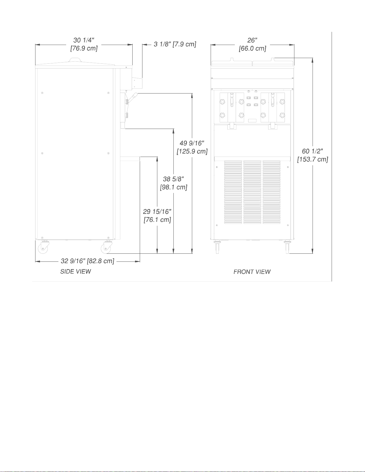
1.3 FreezerSpecifications....................................................................................... 2
2. INSTALLATION INSTRUCTIONS
2.1 SafetyPrecautions............................................................................................. 3
2.2 ShipmentandTransit ......................................................................................... 3
2.3 FreezerInstallation ............................................................................................. 3
2.4 InstallingPermanentWiring ................................................................................ 4
3. INITIAL SET-UP AND OPERATION
3.1 Operator'sSafetyPrecautions............................................................................ 5
3.2 OperatingControlsandIndicators ...................................................................... 5
3.3 DisassemblyofFreezerParts ............................................................................ 5
3.4 CleaningtheFreezerParts ................................................................................ 6
3.5 SanitizeFreezerandFreezerParts.................................................................... 6
3.6 AssemblyofFreezer .......................................................................................... 6
3.7 Sanitizing ........................................................................................................... 7
3.8 Cleaning&SanitizingofSO328withFill-o-maticIIandFill-o-maticIII.................. 8
3.9 InitialFreezeDownandOperation ..................................................................... 8
3.10 RemovingProduct ............................................................................................. 8
3.11 SO328Operation............................................................................................... 8
4. PREVENTATIVE MAINTENANCE
4.1 RoutineCleaning ............................................................................................... 11
4.2 PreventativeMaintenance .................................................................................. 11
4.3 ExtendedStorage.............................................................................................. 11
4.4 ConsistencyAdjustment..................................................................................... 11
5. REPLACEMENT PARTS INFORMATION
5.1 OrderingParts ................................................................................................... 13
5.2 ReferenceDrawing ............................................................................................ 13
6. ACCESSORIES
6.1 Fill-o-maticII....................................................................................................... 15
6.2 Fill-o-maticIII ...................................................................................................... 17
6.3 Fill-o-maticConnections .................................................................................... 19
TABLE OF CONTENTS

FIGURE TITLE PAGE
1 Model SO328 ................................................................................... 1
2 FreezerSpecifications...................................................................... 2
3 LevelingUnit ..................................................................................... 3
4 ElectricalBox.................................................................................... 4
5 Controls ............................................................................................ 5
6 DisassemblingFreezer..................................................................... 6
7 FrontDoorandAugerAssembly ....................................................... 6
8 RearSealAssembly ......................................................................... 6
9 ConsistencyAdjustment....................................................................11
10 Fill-o-maticII .....................................................................................16
11 Fill-o-maticIII.....................................................................................18
LIST OF ILLUSTRATIONS

1
1.1 REMOTE POSSIBILITIES
TheStoelting Optima deliversfrozen drink profits bythe pitcher.TheModel SO328 isa high-volume producerof
ready-to-serve frozen cocktails or frozen neutral base for those special drink recipes. From an extra-small space,
the Optima’s compact design and high capacity output will give you extra-large profits.
SECTION 1
INTRODUCTION
Figure 1. Model SO328
1.2FEATURES
High Capacity
- 15-18gallons per hour per
cylinderoutput
- Thick, stackable slush for
post-mixing
- Or, ready-to-serve pre-mixed
products
High Efficiency Evaporator/Auger
- Stainless steel construction
- Long life auger blades
- Quiet, smooth operation
- 8 qt. freezing cylinder capacity
ConsistencyControl
- Adjustable for thick or thin
products
- Sensitiveto product demand
- 24 volt control circuits
Dispensing Head Door
- ”No-Freeze”designprevents
blockages
- Fast dispense for quick fill of
pitchers
- Controlled dispense for drinks
by the glass
- Convenientpull-type handle
- Attractive, clear, see-thru
design
- Visible,moving product for
merchandising appeal

2
Electrical Refrigeration Crated Dimensions Dimensions
208/230/60/1 HFC-404Aenvironmentally- Width: 22" (55.9cm) Width:17.6"(44.7cm)
20 amp circuit & plug friendlyrefrigerant Depth:30" (76.2cm) Depth:26.1"(66cm)
per side 2HP (14,800 BTUH) high- Height:66" (167.7cm) Height: 61.2"(155cm) w/casters
12running amps efficiency compressor Weight:400lbs.(182kg) Weight:350lbs.(159kg)
1/2HP Drive Motor Air or water cooled.
1.3FREEZERSPECIFICATIONS
Figure 2. Freezer Specifications

3
SECTION 2
INSTALLATION INSTRUCTIONS
2.1 SAFETY PRECAUTIONS
Do not attempt to operate the freezer until the safety
precautionsandoperatinginstructionsinthismanualare
read completely and are thoroughly understood.
Take notice of all warning labels on the freezer. The
labels have been put there to help maintain a safe
working environment. The labels have been designed to
withstand washing and cleaning. All labels must remain
legible for the life of the freezer. Labels should be
checked periodically to be sure they can be recognized
as warning labels.
Ifdanger,warningorcautionlabelsareneeded,indicate
the part number, type of label, location of label, and
quantity required along with your address and mail to:
STOELTING, INC.
ATTENTION: Customer Service
502 Hwy. 67
Kiel, Wisconsin 53042
Figure 3. Leveling Unit
A.Uncratethefreezer.
B.Thefreezermustbeplacedinasolidlevelposition.To
level adjust casters. Figure 3.
C. Thefreezerisequippedwithanaircooledcondenser
and requires correct ventilation; the front is the intake
and the back is the discharge. Both front and back
require3"clearanceforproperoperation.
D. Place all switches in the OFF position.
E. Connectthetwopowercords.Theplugisdesignedfor
208/230volt/20ampduty.Theunitmustbeconnected
toaproperlygroundedreceptacle.Theelectricalcord
furnishedaspartofthefreezerhas a three prong
grounding type plug. The use of an extension cord is
not recommended. If one must be used, use one with
a size12 gaugeorheavierwithagroundwire. Donot
useanadaptortogetaroundgroundingrequirements.
CAUTION
DONOTALTERORDEFORMPLUGINANYWAY!
F. Installthedriptray,coverandothermiscellaneous
parts on the freezer.
2.2SHIPMENTANDTRANSIT
The freezer has been assembled, operated and in-
spected at the factory. Upon arrival at the final destina-
tion, the complete freezer must be checked for any
damage which may have occurred during transit.
With the method of packaging used, the freezer should
arrive in excellent condition. THE CARRIER IS RE-
SPONSIBLE FOR ALL DAMAGE IN TRANSIT,
WHETHER VISIBLE OR CONCEALED. Do not pay the
freight bill until the freezer has been checked for dam-
age. Have the carrier note any visible damage on the
freightbill.Ifconcealeddamageand/orshortageisfound
later, advise the carrier within 10 days and request
inspection. The customer must place claim for damages
and/orshortages in shipment withthecarrier.Stoelting,
Inc. cannot make any claims against the carrier.
2.3FREEZERINSTALLATION
Installationofthefreezerinvolvesmovingthefreezerclose
to its permanent location, removing all crating, setting in
place,assemblingparts, and cleaning.

4
2.4INSTALLINGPERMANENTWIRING
Ifpermanentwiringisrequiredbylocalcodes,thefollowing
proceduremustbeperformed.
WARNING
DISCONNECT FREEZER FROM THE SOURCE
OF ELECTRICAL SUPPLY BEFORE SERVICING.
A. Removetherightsideandleftpanelsandelectricalbox
covers to gain access to the power cord.
B. Removethestrainreliefconnectorfromthebottomof
thefreezerbasecutandremovethe powercord.
C. Installpermanent wiring according to local code.
D. Connect black wire to black wire. Connect the white
wireto white wire.Connect the green oryellow and
greenstripedgroundwiretothegroundingscrew.
E. Replace all coversand panels.
Figure 4. Electrical Box

5
SECTION 3
INITIAL SETUP AND OPERATION
3.1OPERATOR'SSAFETYPRECAUTIONS
SAFEOPERATION IS NOACCIDENT;Observe these
rules:
A. Know the freezer. Read and understand the
OperatingInstructions.
B. Notice all warning labels on the freezer.
C. Wear proper clothing. Avoid loose fitting garments,
andremove watches, ringsor jewelry whichcould
cause a serious accident.
D. Maintain a clean work area. Avoid accidents by
cleaning up the area and keeping it clean.
E. Stay alert at all times. Know which switch, push
button or control you are about to use and what
effect it is going to have.
F. Disconnect electrical cord for maintenance.
Neverattemptto repair or performmaintenanceon
the freezer until the main electrical power has been
disconnected.
G. Do not operate under unsafe operating condi-
tions. Neveroperate the freezer ifunusualor exces-
sivenoise or vibration occurs.
3.2OPERATINGCONTROLSANDINDICATORS
Beforeoperating the freezer, itis required thatthe
operatorknow the functionofeach operating control.
Referto Figure 4for the locationof the operating
controlson the freezer.
A. Pump OFF/ON Switch
The pump OFF/ON Switch is a two position switch.
In the OFF position the pump will not run. In the ON
position the pump will run until the proper liquid level
is reached, then stop. If the hopper does not fill
completely, place the switch in the OFF position,
then back to ON to continue filling.
WARNING
THE CLEAN/OFF/SERVE SWITCH MUST BE PLACED
IN THE OFF POSITION WHEN DISASSEMBLING FOR
CLEANING OR SERVICING. THE FREEZER MUST BE
DISCONNECTED FROM ELECTRICAL SUPPLY BE-
FORE REMOVINGANYACCESS PANEL.
B. CLEAN/OFF/SERVESwitch
The CLEAN/OFF/SERVE switch is a three position
toggleand refrigeration switch used to control the
operation of the agitator. When the switch is placed
in the CLEAN position, the agitator will rotate.
When the switch is placed in the OFF position, nothing
will operate. When the switch in placed in the SERVE
position, the agitator and refrigeration system will run
until proper consistency is reached then stop.
C. Mix Low Light
The Mix Low light will illuminate when you are low on
mix.
CAUTION
DO NOT OPERATE FREEZER WHEN THE LOW
MIX LIGHT IS ILLUMINATED OR DAMAGE TO
THEFREEZERCOULD RESULT.
3.3 DISASSEMBLY OF FREEZER PARTS
CAUTION
PLACETHECLEAN/OFF/SERVE SWITCHINTHE
OFF POSITION BEFORE DISASSEMBLING FOR
CLEANINGORSERVICING.
Inspectionfor worn orbroken parts shouldbe made at
everydisassembly of thefreezerfor cleaning orother
purposes.All worn orbroken parts shouldbe replaced
to ensure safety to both the operator and the customer
andto maintain good freezerperformance and a quality
product. Frequency of cleaning must comply with the
localhealth regulations.
To disassemble the freezer, refer to the following steps:
A. Removehoppercover.
B. Remove the frontdoor by turning offthe knobs, and
then pull the front door off the studs.
Figure 5. Controls
Clean Off Serve Switch
Pump Off On Switch
Mix Low

6
Figure 6. Disassembling Freezer
C. Removethespigot body fromthe front door bypulling
the retaining pin out of the spigot handle. Push the
spigot body thru the bottom of the front door.
D. Removetheagitatorassembly from thefreezer.Pull
the agitator assembly out of the freezer barrel.
E. Keep the rear of the agitator assembly tipped up
once it is clear of the freezer barrel to avoid dropping
rearseal.
F. Remove the front agitatorsupportbearing and the
twoagitator blades.
G. Removethe rear sealassembly.
H. Wipesocketlubricant from thedrive end (rear)of the
agitator with a cloth or paper towel.
I. Removeall “O” Rings.
WARNING
DONOTUSEANYTYPEOFSHARPOBJECT TO
REMOVE THE “O” RINGS.
Figure 7. Front Door and Auger Assembly
Figure 8. Rear Seal Assembly
3.4CLEANINGTHE FREEZER PARTS
Place all loose parts in a pan or container and take to
the wash sink for cleaning.To clean freezer parts refer
to the following steps:
A. Place all parts in warm (120°F) mild detergent (Joy
orequivalent)waterand clean with brushes provided.
Rinse all parts with clean hot (135°F) water.
CAUTION
DO NOT DAMAGE PARTS BY DROPPING OR
ROUGHHANDLING.
B. Wash the freezerbarrelwith warm (120°F) detergent
(Joyorequivalent)waterandbrushesprovided.
C. The exterior should be kept clean at all times to
perserve the lustre of the stainless steel. A mild
alkaline cleaner is recommended. Use a soft cloth or
sponge to apply the cleaner.
D. Removethedrip tray insertand drain tray. Clean with
adetergent solution (Joyorequivalent). Rinse with
cleanhot water.
3.5SANITIZEFREEZERAND FREEZER PARTS
A. Use a sanitizer mixed according to manufacturer’s
instructions to provide a 100 parts per million
strength solution. Mix sanitizer in quantities of no
less than 4 gallons (15 liters) of 120°F water.Allow
the sanitizer to contact the surfaces to be sanitized
for 5 minutes. Any sanitizer must be used only in
accordancewith the manufacturer’sinstructions.
B. Place all parts in the sanitizing solution, then remove
and let air dry.
3.6ASSEMBLY OF FREEZER
Toassemble the freezerparts,refertothe following
steps:
NOTE
Petro-Gelsanitary lubricant orequivalent must beused
whenlubrication of parts is specified.
SOFTRUBBER
SURFACE HARD CARBON
SURFACE

7
WARNING
THE UNITED STATES DEPARTMENT OF AGRI-
CULTUREAND FOOD ANDDRUGADMINISTRA-
TIONREQUIRETHATALLCLEANINGANDSANI-
TIZING SOLUTIONS USED WITH FOOD PRO-
CESSINGEQUIPMENTBECERTIFIED FOR THIS
USE.USE“STERA-SHEEN”OREQUIVALENT.
When sanitizing the freezer, refer to local sanitary
regulationsforapplicable codes and recommended
sanitizingproducts and procedures. Thefrequencyof
sanitizing must comply with local health regulations.
Mix sanitizer according to manufacturer’s instructions
to provide a 100 parts per million strength solution. Mix
sanitizer in quantities of no less than 4 gallons (15
liters) of 120°F water. Allow sanitizer to contact the
surfaces to be sanitized for 5 minutes. Any sanitizer
must be used only in accordance with the
manufacturer’sinstructions.
NOTE
Stoelting, Inc. has found that STERA-SHEEN
GREENLABEL SANITIZER ANDCLEANER does
aneffectivejobofproperlysanitizingandcleaninga
soft serve freezer. We therefore include a sample
witheach new freezer. Forfurther information read
the directions on the packet. Other products may
beaseffective.
CAUTION
PROLONGED CONTACT OF SANITIZER WITH
FREEZER MAYCAUSE CORROSION OF STAIN-
LESS STEEL PARTS.
In general, sanitizing may be conducted as follows:
A. Prepare 4 gallons (15 liters) of sanitizing solution
followingmanufacturers instructions, then pourinto
hopper,brush hopperwalls,and inside of hopper
cover.
If using an auto fill. Pour sanitizing solution into the
mix container, brush mix container, draw tube and
pick up hose. Pump sanitizer from mix containers
intothe freezer hopper. Brushhopper walls, hopper
cover, hoseadapterand retainingclip.
B. Place the CLEAN/OFF/SERVE switch in the CLEAN
position. Check for leaks around the front door seal.
C. Afterfiveminutes, open spigotto drain sanitizing
solution. When solution has drained, place the
CLEAN/OFF/SERVE switch in the OFF position.
Allowthe freezer barrel to draincompletely.
NOTE
TheUnitedSatesDepartmentofAgricultureand the
FoodandDrug Administrationrequirethatlubricants
usedon food processingequipmentbe certified for
this use. Use lubricants only in accordance with
themanufacturer’s instructions.
A. Assemble spigot “O” Rings onto parts dry, without
lubrication. Then apply a thin film of sanitary
lubrication to exposed surfaces of the “O” Rings.
B. Assemble the rear seal assembly onto the agitator.
Be sure the “O” Ring is in place before installing
the rear seal. Do not lubricate.
C. Lubricatetheagitator drive (rear) witha small
amount of white socket lubricant. A small container
of socket lubricant is shipped with the freezer.
D. Install the two plastic agitator blades onto the
agitator. Installfront agitatorbearing to the door.
E. Push the augerinto the freezerbarrel and rotate
slowly until the agitator engages the drive socket.
F. Install the spigot body with “O” Rings into the front
door from the bottom. Push straight up until the
spigot is in place. Place the spigot handle into the
spigot and insert the retainer pin.
G. Installdoor “O” Ringafter lubricating.
H. Installthefront door on thefreezer.
I. Install the knobs on the freezer studs.
CAUTION
FINGERTIGHTENTHE KNOBSEVENLY. DONOT
OVER-TIGHTENKNOBS.
Lookfor the proper sealbetween the freezer barreldoor,
“O”Ring, and front door.
J. Installhoppercover.
3.7 SANITIZING
Sanitizing must be done after the freezer is clean and
just before filling with mix. Sanitizing the night before
is not effective. However,you should alwaysclean the
freezer and parts after using it.

8
ÊÊ
ÊÊ
Ê
3.8 CLEANING & SANITIZING OF S0328 WITH
FILL-O-MATIC IIAND FILL-O-MATIC III
A. Empty freezer & mix container of product.
B. Mix 4 gallonsof warm (120°F)detergent (Joy or
equivalent)water and pour intomix container,brush
mix container, pick up hose and draw tube. Pump
detergentwaterintofreezerhopper.
C. Mix sanitizer according to manufacturers instructions
in quantities no less than 4 gallons. Pour sanitizer
into mix container. Brush mix container, hose and
draw tube to sanitize. Pump sanitizer into freezer
hopper, emptyremaining sanitizer frommix container
and let air dry.
D. Draindetergent&sanitizer solution fromthe freezer.
E. Disassemble freezer according to Section 3, 3.3.
F. Clean freezer and parts according to Section 3, 3.4.
G. Sanitize freezer & parts according to Section 3, 3.5.
H. Assemble per Section 3, 3.6.
I. Sanitize per Section 3, 3.7.
3.9 INITIAL FREEZE DOWNAND OPERATION
Thissection covers the recommendedoperating
proceduresto be followedfor the safe operationof the
freezer.
A. Sanitize just prior to use.
B. Place the CLEAN/OFF/SERVE switch in the OFF
position.
C. With the spigot open, pour one cup of mix into the
hopper.Allow approximately 8 oz. of sanitizing
solution and mix to drain out. Close the spigot and
fill the hopper with mix.
D. Place the CLEAN/OFF/SERVE switch in the
SERVE position. The product will be ready to serve
in about 15 minutes.
3.10REMOVINGPRODUCT
Beforedisassembly,all product must be removed.
A. Open spigot andcompletely drain freezer.
B. Prepare not lessthan 3 gallons of warmdetergent
water and pour into hopper. (When using auto fill
pumpthru auto fill).
C. Use a brush to clean the hopper then completely
drainfreezer.
3.11 SO328 OPERATION INFORMATION FOR
SERVICE PERSONNEL
The SO328 is a cocktail/slush freezer. It is available in
208-230volt,either air-cooled or water-cooled. Theair-
cooledversionhas front-to-back airflow requiring three
inches of air space in the front and back for proper
refrigeration. This unit is not supplied with a pump,
however, Stoelting doesofferthe Fill-O-MaticII (electric)
andFill-O-Matic III (gas)pumps. This freezeris intended
for use with non-dairy products only and will produce
15-18GPH.
1. Filling
To fill the freezer, pour mix into hopper until full. To fill
freezerswith the optionalFill-O-Matic pump, connect
the pump and turn the pump switch on, electric model
or turn the gas on, gas model. Then turn the pump
switch on, located on the freezer, this will open the
solenoidvalve and the freezerwillbegin to fill.The
liquid level control circuit is designed with a fill timer.
This timer is designed to shut the compressor off if
the top level probe is not satisfied before the timer
expires. If the top level probe is not satisfied before the
timer times out, it locks the compressor out and
freezing will not occur, if this happens, turn the fill
switch off and then back on, this will reset the timer.
2. Operation
Oncethe freezer isfull of mix,turn the clean-off-serve
switch to the “serve” position. The drive motor will start
immediately. The compressor utilizes a 10 second
delay-on-make/delay-on-break timer therefore, the
compressor will start 10 seconds later. The compressor
will continue to run until the drive motor torque switch is
satisfied, then after a 10 second delay stop. The drive
motor runs continuously in the “serve” or “clean” switch
positions. There is no night mode or standby mode. If
productis left inthe freezer overnightwe recommend to
simply turn the freezer off. Do not run the freezer in
"clean” overnight. Freeze down time will typically be 6-
10 minutes depending on the type of product used and
thestarting product temperature.
3. Pump Operation
When the mix level in the hopper drops below the
bottomlevelprobe, the solenoid valveopensand the
pump begins to fill until the top level probe is satisfied.
Whensatisfied, the solenoidvalve closes, andpump
will continue to run until shut off pressure is reached.
The electric pump will run until the pressure reaches the
cut-out pressure of the pump. A gas pump will continue
to run until the pressure in the mix line equals the gas
pressure of the pump. If you wish to use the product in
the hopper prior to cleaning, turn the mix pump off and
turn the freezer pump switch off. This will disable the fill
timer and allow the compressor to continue to run. Be
cautioned that once the hopper is empty, the barrel
could freeze up. Only run the freezer until the hopper is
empty or damage may occur.

9
4. Fill Timer Operation
The timer has ten dip switches, all switches placed in
the “on” position are added together to make up the
total time delay. This freezer leaves the factory with 64,
128 and 256 in the “on” position, this is a total of 448
seconds. The preset time should be enough to fill the
hopper up to the top level probe. Fill time may be depen-
dent on what style pump is employed. The purpose of
the timer is to disable the compressor if the mix supply
runs out. When the timer expires, the mix low light will
illuminate. If the mix low light is illuminated, the com-
pressor is locked out of the electrical circuit and will not
run. It may be necessary to change the timer settings
to more closely match the pumping capacity of your
pump.

10

11
4.1ROUTINECLEANING
Toremove spilled ordried mix fromthefreezer exterior,
simply wash in the direction of the finish with warm
soapy water and wipe dry. Do not use highly abrasive
materials as they will mar the finish.
4.2PREVENTATIVE MAINTENANCE
It is recommended that a maintenance schedule be
followedto keep the freezercleanand operating prop-
erly.
WARNING
NEVER ATTEMPT TO REPAIR OR PERFORM
MAINTENANCE ON FREEZER UNTIL THE MAIN
ELECTRICAL POWER HAS BEEN DISCON-
NECTED.
A. Daily
1. The exterior should be kept clean at all times to
preserve the lustre of the stainless steel. A mild
alkaline cleaner is recommended. Use a soft cloth or
sponge to apply the cleaner.
2. Removethedrip tray andinsert. Clean thedrip
tray and insert and front of the freezer with a soap
solution.
B. Weekly
1. Check“O”Ringsand rear sealfor excessive wear
and replace if necessary.
2. Clean filter.To remove lift up and pull bottom out and
down, then wash, dry and reinstall.
C. Monthly
CAUTION
THE FREEZER HAS AN AIR COOLED CON-
DENSERANDMUSTHAVEPROPERAIRCIRCU-
LATION. FAILURETO CLEANTHECONDENSER
ON A REGULAR BASIS MAY RESULT IN SERI-
OUS FREEZER DAMAGE AND COULD VOID
FREEZERWARRANTY.
1. Visually inspect the condenser for dirt by shining a
light through the coil from the fan side of the con-
denser.
2. If the condenser is dirty, using compressed air or
CO2 tank, blow out the dirt from the fan side of the
condenser.
3. Analternativemethod of cleaningthe condenser isto
usea condenser brush andvacuum.
NOTE
Ifthe condenser is not kept clean, loss ofrefrigera-
tionefficiencywillresult, causing extended run time
or soft product consistency.
4.3EXTENDEDSTORAGE
Referto the followingsteps for storageof the freezer
overany long period ofshutdowntime:
A. Turn CLEAN/OFF/SERVE switch to the OFF
position.
B. Disconnect (unplug) fromthe electrical supply
source.
C. Cleanthoroughlywith a warmdetergent all partsthat
come in contact with the mix. Rinse in clear water
and dry all parts. Do not sanitize.
NOTE
Do not let the cleaning or sanitizing solution stand
inthehopperorinthefreezerbarrelduringtheshut-
downperiod.
D. Remove,disassemble,andclean the frontdoor, and
agitator parts. Place the agitator blades and the front
agitator support bearing in a plastic bag with a moist
papertowel to preventthemfrom becoming brittle.
4.4CONSISTENCYADJUSTMENT
The consistency adjustment knob is located behind the
back panel. Remove the lower back panel to access.
Turnclockwise for a thicker productand counterclock-
wise for a thinner product. Figure 9. Allow 15-30
minutes for the product to change consistency.
WARNING
DONOTOPERATEFREEZERWITHBACKPANEL
REMOVED.
SECTION 4
PREVENTIVE MAINTENANCE
Figure9. ConsistencyAdjustment

12
Table of contents
Other Stoelting Dispenser manuals

Stoelting
Stoelting Endura 131G User manual

Stoelting
Stoelting CW5-37B Release Note

Stoelting
Stoelting E131I2 User manual

Stoelting
Stoelting O111-I2F User manual

Stoelting
Stoelting C111 User manual

Stoelting
Stoelting CW5-37A Release Note

Stoelting
Stoelting CF101 User manual

Stoelting
Stoelting SHAKE MACHINE User manual

Stoelting
Stoelting O231-I2F User manual

Stoelting
Stoelting F131-YG2 User manual
Popular Dispenser manuals by other brands

Borg & Overstrom
Borg & Overstrom U2 Install & Operation Manual

Wayne
Wayne Vista Series Service

AUTOMATED EQUIPMENT
AUTOMATED EQUIPMENT McDonald's DF22 Equipment manual

NOBLE CHEMICAL
NOBLE CHEMICAL Novo 158NOVAK55SS instruction manual

Hewi
Hewi 805.06.150 Mounting instructions

Estilo
Estilo 0341861 user manual