Stollmann BlueMod+SR/AP Application guide

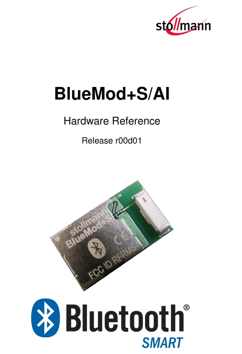
BlueMod+SR/AI
BlueMod+SR/AP
Hardware Reference
Release r09

BlueMod+SR/AI
BlueMod+SR/AP
Hardware Reference
Release r09 www.stollmann.de Page 2 of 76
Note
This device was developed for the purpose of communication in an office environment. It is
intended solely for our industrial clients for physical integration into their own technical products
after careful examination by experienced technical personnel for its suitability for the intended
purpose. The device was not developed for or intended for use in any specific customer
application. The firmware of the device may have to be adapted to the specific intended modalities
of use or even replaced by other firmware in order to ensure flawless function in the respective
areas of application. Performance data (range, power requirements, etc.) may depend on the
operating environment, the area of application, the configuration, and method of control, as well as
on other conditions of use; these may deviate from the technical specifications, the Design Guide
specifications, or other product documentation. The actual performance characteristics can be
determined only by measurements subsequent to integration. Variations in the performance data of
mass-produced devices may occur due to individual differences between such devices. Device
samples were tested in a reference environment for compliance with the legal requirements
applicable to the reference environment. No representation is made regarding the compliance with
legal, regulatory, or other requirements in other environments. No representation can be made and
no warranty can be assumed regarding the suitability of the device for a specific purpose as
defined by our customers. Stollmann reserves the right to make changes to the hardware or
firmware or to the specifications without prior notice or to replace the device with a successor
model. Of course, any changes to the hardware or firmware of any devices for which we have
entered into a supply agreement with our customers will be made only if, and only to the extent
that, such changes can reasonably be expected to be acceptable to our customers. No general
commitment will be made regarding periods of availability; these must be subject to individual
agreement. All agreements are subject to our Terms and Conditions for Deliveries and Payments,
a copy of which is available from Stollmann.
Copyright © 2015 Stollmann E+V GmbH
Trademarks
The Bluetooth®word mark and logos are owned by the Bluetooth SIG, Inc. and any use of such
marks by Stollmann E+V GmbH is under license. Other trademarks and trade names are those of
their respective owners.

BlueMod+SR/AI
BlueMod+SR/AP
Hardware Reference
Release r09 www.stollmann.de Page 3 of 76
Table of contents
1Introduction..............................................................................................................................8
1.1 Feature Summary.............................................................................................................8
1.2 Applications......................................................................................................................9
1.2.1 General Cable Replacement......................................................................................9
1.2.2 Industry......................................................................................................................9
1.2.3 Automotive.................................................................................................................9
1.2.4 Healthcare and Medical.............................................................................................9
1.2.5 Sports and Fitness...................................................................................................10
1.2.6 Entertainment..........................................................................................................10
2Block Diagram .......................................................................................................................11
3Application Interface ..............................................................................................................12
3.1 Power Supply .................................................................................................................12
3.2 Power-up / -down Slew-Rate ..........................................................................................12
3.3 Reset..............................................................................................................................12
3.4 Supply Voltage Monitor...................................................................................................14
3.5 Serial Interface................................................................................................................15
3.5.1 3-Wire Serial Interface.............................................................................................16
3.5.2 Baud Rate Deviation................................................................................................18
3.6 GPIO Interface................................................................................................................20
3.7 I2C Interface....................................................................................................................20
3.8 NFC Support...................................................................................................................20
3.9 SPI Serial Peripheral Interface........................................................................................21
3.10 Bluetooth Radio Interface ...............................................................................................22
3.11 WLAN Coexistence Interface..........................................................................................22
3.12 Slow Clock Interface.......................................................................................................23
3.13 Test Mode Enable...........................................................................................................23
3.14 Pin Strapped System Memory Boot Mode Invocation .....................................................23
3.15 Operating in a Power-Switched Environment..................................................................24
3.16 Serial Wire DEBUG Interface..........................................................................................24
3.17 TRACE Interface.............................................................................................................24
4Module Pins...........................................................................................................................25

BlueMod+SR/AI
BlueMod+SR/AP
Hardware Reference
Release r09 www.stollmann.de Page 4 of 76
4.1 Pin Numbering................................................................................................................25
4.2 Pin Description................................................................................................................26
4.2.1 General Pin Description...........................................................................................26
4.2.2 Application Specific Pin Description.........................................................................27
4.2.2.1 SPP Pin Configuration..........................................................................................27
4.3 Handling of Unused Signals............................................................................................28
5Electrical Characteristics........................................................................................................29
5.1 Absolute Maximum Ratings ............................................................................................29
5.2 Electrical Requirements..................................................................................................29
5.3 Operating Conditions......................................................................................................29
5.4 Environmental Requirements..........................................................................................30
5.5 Digital I/O Including EXT-RES# ......................................................................................30
5.6 Power Consumption and Power Down Modes................................................................33
5.6.1 Classic Bluetooth.....................................................................................................33
5.6.2 LE Configurations....................................................................................................34
5.6.2.1 LE Operating in Peripheral Device Role...............................................................34
5.6.2.2 LE Operating in Central Device Role....................................................................35
5.7 RF Performance .............................................................................................................37
5.7.1 GFSK, PI/4 DQPSK, 8DPSK Receiver.....................................................................37
5.7.2 GFSK, PI/4 DQPSK, 8DPSK Transmitter.................................................................40
5.7.3 BLE Receiver...........................................................................................................43
5.7.4 BLE Transmitter.......................................................................................................44
5.7.5 Antenna-Gain and Radiation Pattern .......................................................................46
5.8 Power-Up Time...............................................................................................................48
6Mechanical Characteristics....................................................................................................49
6.1 Dimensions.....................................................................................................................49
6.2 Recommended Land Pattern..........................................................................................50
6.3 Re-flow Temperature-Time Profile..................................................................................51
6.4 Placement Recommendation..........................................................................................52
6.5 Housing Guidelines.........................................................................................................52
6.6 Antenna Issues...............................................................................................................52
6.7 Safety Guidelines............................................................................................................53

BlueMod+SR/AI
BlueMod+SR/AP
Hardware Reference
Release r09 www.stollmann.de Page 5 of 76
6.8 Cleaning .........................................................................................................................53
7Application Diagram...............................................................................................................54
8Approvals/Certifications.........................................................................................................55
8.1 Declaration of Conformity CE..........................................................................................55
8.2 FCC Compliance ............................................................................................................55
8.2.1 FCC Grant...............................................................................................................56
8.2.2 FCC Statement........................................................................................................58
8.2.3 FCC Caution............................................................................................................58
8.2.4 FCC Warning...........................................................................................................58
8.2.5 FCC RF-exposure Statement...................................................................................58
8.2.6 FCC Labeling Requirements for the End Product ....................................................59
8.3 IC Compliance................................................................................................................59
8.3.1 IC Grant...................................................................................................................60
8.3.2 IC Statement............................................................................................................61
8.3.3 IC Caution................................................................................................................61
8.3.4 IC RF-exposure Statement ......................................................................................61
8.3.5 IC Labeling Requirements for the End Product........................................................62
8.3.6 IC Label Information BlueMod+SR...........................................................................62
8.4 KCC Certification Grant ..................................................................................................63
8.5 MIC Certification.............................................................................................................64
8.6 Bluetooth Qualification....................................................................................................68
8.7 RoHS Declaration...........................................................................................................69
9Related Documents ...............................................................................................................69
10 Packing...............................................................................................................................70
10.1 Tape...............................................................................................................................71
10.2 Reel................................................................................................................................71
10.3 Package Label................................................................................................................72
11 Ordering Information ...........................................................................................................73
11.1 Part Numbers..................................................................................................................73
11.2 Standard Packing Unit....................................................................................................73
11.3 Evaluation Kit..................................................................................................................73
12 History.................................................................................................................................74

BlueMod+SR/AI
BlueMod+SR/AP
Hardware Reference
Release r09 www.stollmann.de Page 6 of 76
List of Figures
Figure 1: BlueMod+SR Block Diagram..........................................................................................11
Figure 2: BlueMod+SR Example Power Supply............................................................................12
Figure 3: BlueMod+SR Example Reset.........................................................................................13
Figure 4: Serial Interface Signals..................................................................................................15
Figure 5: BlueMod+SR Example Serial Interface (RS-232) Supporting UICP ...............................16
Figure 6: BlueMod+SR Example Serial Interface (Mixed Signal Level) .........................................17
Figure 7: BlueMod+SR I2C Interface.............................................................................................20
Figure 8: Connection to the NFC Tag NXP: NT3H1101 ................................................................21
Figure 9: BlueMod+SR SPI Interface e.g. in Master Mode............................................................22
Figure 10: Unity 3e WLAN Coexistence........................................................................................22
Figure 11: BlueMod+SR Pin Numbering (Top View) .....................................................................25
Figure 12: Typical Antenna Radiation Pattern at 2402MHz...........................................................46
Figure 13: Typical Antenna Radiation Pattern at 2441MHz...........................................................47
Figure 14: Typical Antenna Radiation Pattern at 2480MHz...........................................................47
Figure 15: BlueMod+SR/AI dimensions.........................................................................................49
Figure 16: BlueMod+SR/AP dimensions.......................................................................................49
Figure 17: BlueMod+SR Land Pattern ..........................................................................................50
Figure 18: Soldering Temperature-Time Profile (For Reflow Soldering)........................................51
Figure 19: BlueMod+SR/AI Placement Recommendation.............................................................52
Figure 20: Typical Application Schematics....................................................................................54
List of Tables
Table 1: Power up/down Slew Rate Requirements .......................................................................12
Table 2: Pin States during Reset...................................................................................................14
Table 3: Standard Baud Rates and Deviations..............................................................................18
Table 4: General Pin Assignment..................................................................................................26
Table 5: Application Specific Pin Assignments, SPP.....................................................................27
Table 6: Absolute Maximum Ratings.............................................................................................29

BlueMod+SR/AI
BlueMod+SR/AP
Hardware Reference
Release r09 www.stollmann.de Page 7 of 76
Table 7: Electrical Requirements ..................................................................................................29
Table 8: DC Operating Conditions ................................................................................................29
Table 9: Environmental Requirements..........................................................................................30
Table 10: DC Characteristics, Digital IO (STM32-related).............................................................31
Table 11: DC Characteristics, SLCK (STM32 Backup Domain).....................................................31
Table 12: DC Characteristics, Digital IO (CSR8811 Related)........................................................32
Table 13: Supply Current SPP Sleep Modes no Radio Activity .....................................................33
Table 14: Supply Current, SPP Bluetooth Classic.........................................................................33
Table 15: Supply Current BLE Terminal I/O Profile, Peripheral Device Role, Standby..................34
Table 16: Supply Current BLE Terminal I/O Profile, Peripheral Device Role, CI 7,5ms.................34
Table 17: Supply Current BLE Terminal I/O Profile, Peripheral Device Role, CI 37,5ms...............34
Table 18: Supply Current BLE Terminal I/O Profile, Central Device Role, Standby.......................35
Table 19: Supply Current BLE Terminal I/O Profile, Central Device Role, CI 7,5ms......................35
Table 20: Supply Current BLE Terminal I/O Profile, Central Device Role, CI 37,5ms....................36
Table 21: RF Performance GFSK, PI/4 DQPSK, 8DPSK Receiver ...............................................39
Table 22: RF Performance GFSK, PI/4 DQPSK, 8DPSK Transmitter ...........................................42
Table 23: RF Performance BLE Receiver.....................................................................................43
Table 24: RF Performance BLE Transmitter .................................................................................45

BlueMod+SR/AI
BlueMod+SR/AP
Hardware Reference
Release r09 www.stollmann.de Page 8 of 76
1 Introduction
This Hardware Reference documents how the BlueMod+SR/AI and BlueMod+SR/AP can be
integrated into customer systems. It addresses hardware specifications of the BlueMod+SR/AI and
/AP and requirements of the hardware environments for the BlueMod+SR/AI and BlueMod+SR/AP.
Notation: The term BlueMod+SR refers to both the BlueMod+SR/AI and the BlueMod+SR/AP.
For detailed information about software interfaces refer to [5].
For the latest version of this document please check the following URL:
http://www.stollmann.de/en/support/downloads/bluetooth-adapter/bluemod-sr.html
1.1 Feature Summary
Bluetooth specification V4.0 compliant
Supports BR/EDR/LE
Supports Dual Mode
Fully qualified Bluetooth V4.0 Dual Mode BR/EDR/LE
CE certified
FCC, IC and KCC certified
CSR8811 BlueCore08 and Application Processor inside
Complete Co-location and Co-existence with 802.11 (AFH, Unity 3e+)
Fast Connection Setup
RF output power up to +7dBm with power control
Supply Voltage range 2,5V to 3,6V, typical 3.3V
Internal crystal oscillator (26 MHz and 14,7456 MHz)
LGA Surface mount type: BlueMod+SR: 17 x 10 x 2.6 mm3
Shielded to be compliant to FCC full modular approval
Bluetooth enhanced data rate up to 2178kbps asymmetric
Support for all Bluetooth power saving modes (Park, Sniff, Hold)
Optional support for ultra-low-power mode
Full 8- to 128-bit encryption
High sensitivity design
High-speed UART interface
I2C interface
SPI interface
Up to 11 digital IO’s for individual usage by embedded software
Cortex-M3 STM32F103 core for embedded profiles or application software
Manufactured in conformance with RoHS2
Operating temperature -30 ... +85 °C
Weight: 0,8 g

BlueMod+SR/AI
BlueMod+SR/AP
Hardware Reference
Release r09 www.stollmann.de Page 9 of 76
1.2 Applications
The BlueMod+SR can be used in different applications. Regardless if the application requires high
throughput or low energy consumption, BlueMod+SR offers the best of both worlds. Some typical
applications are described in this chapter.
Supported profiles are:
BR/EDR:
SPP
LE:
Terminal IO
any GATT based LE-profile
Support for any additional profile is possible on request.
1.2.1 General Cable Replacement
The Serial Port Profile (SPP) on the BlueMod+SR can be used for UART data transfer. The
connection is transparent for the user application and supports Secure Simple Pairing, making the
pairing process easy and the connection secure.
1.2.2 Industry
Typical Bluetooth application include scanner, printer as well as automation controls. In the
automation application area Bluetooth is mainly used for transport of I/O signals. Bluetooth low
energy can be used to monitor and control motors, actuators, values and entire processes.
1.2.3 Automotive
Modules are mainly used in aftermarket application like personal navigation devices, head units or
audio applications. These applications are typically Bluetooth BR/EDR only.
1.2.4 Healthcare and Medical
The healthcare and medical market offers a lot of possible application for Bluetooth BR/EDR and
Bluetooth Low Energy. Usage of Bluetooth is aimed mainly at devices that are used for monitoring
vital data. Typical devices are blood glucose meter, blood pressure cuffs and pulse ox meters.
Bluetooth BR/EDR and low energy were chosen by the Continua Health Alliance as transports for
interoperable end to end communication.

BlueMod+SR/AI
BlueMod+SR/AP
Hardware Reference
Release r09 www.stollmann.de Page 10 of 76
1.2.5 Sports and Fitness
In the sports and fitness segment Bluetooth is used in devices for positioning as well as monitoring
vital data. Typical devices in this market are heart rate monitors, body temperature thermometers,
pedometers, cadence meters, altimeter, positioning / GPS tracking and watches displaying
information from sensors.
1.2.6 Entertainment
Bluetooth technology is already used in a wide variety of devices in the entertainment sector,
namely set-top boxes / gaming consoles. Bluetooth low energy is expected to further increase the
use of Bluetooth technology in devices like TV / DVD / STB / Media Player, remote controls,
gaming controller, wireless mouse/keyboard.

BlueMod+SR/AI
BlueMod+SR/AP
Hardware Reference
Release r09 www.stollmann.de Page 11 of 76
2 Block Diagram
STM32F103
CSR8811
VSUP
BlueMod+SR
BP
Filter
RESET
I2C
UART
GPIO
SPI
WLAN-COEX
1
2
7
3
4
GND
3.3V
26MHz
14,7456MHz
opt. 32kHz
9
EEPROM
DEBUG
onboard
antenna
EXT-ANT
1)
2)
1) BlueMod+SR/AI only
2)BlueMod+SR/APonly
TRACE
Figure 1: BlueMod+SR Block Diagram
Note:
BlueMod+SR/AI has an internal ceramic antenna whereas BlueMod+SR/AP provides for an 50Ω
RF interface

BlueMod+SR/AI
BlueMod+SR/AP
Hardware Reference
Release r09 www.stollmann.de Page 12 of 76
3 Application Interface
3.1 Power Supply
BlueMod+SR require a power supply with the following characteristics:
Typical: 3,3VDC, min.: 2,5VDC, max.: 3.6VDC, > 80mA peak
For optimal performance a stable supply is recommended. If a regulator is to be used, it should be
a fast linear regulator placed as close as possible to the VSUP pins (E-6, F-6). Functionality has
been verified with the following type: TOREX: XC6204x332xx.
If the regulator cannot be placed close to the BlueMod+SR, it is recommended to place an
additional low ESR capacitor with at least 10µF as close as possible to the VSUP pins (E-6, F-6 or
C-1).
BlueMod+SR
XC6204-3.3
C-1,E-6,F-6
VSUP
GND:
A-7,E-7,F-7,B-[5:8],
C-[5:8],D-8,E-8,F-8
10µ + 100n + 1n
1µ
VOUT
VSS
VIN
CE
5 1
3
2
+5VDC
Figure 2: BlueMod+SR Example Power Supply
3.2 Power-up / -down Slew-Rate
Parameter
Min
Max
Unit
VSUP rise time rate
0
∞
µs/V
VSUP fall time rate
20
∞
Table 1: Power up/down Slew Rate Requirements
3.3 Reset
BlueMod+SR are equipped with circuitry for generating Power ON Reset from the internal core
voltage. A reset is generated when the core voltage falls below typically 1,88V and is released
when it rises above typically 1,92V.

BlueMod+SR/AI
BlueMod+SR/AP
Hardware Reference
Release r09 www.stollmann.de Page 13 of 76
By holding pin B-1 (EXT-RES#) at ≤ 0,5V for ≥ 5ms, an external reset is generated. This pin has a
fixed internal pull-up resistor (RPU = 30kΩ... 50kΩ) and a capacitor to GND (100n) which acts as
debounce filter. If EXT-RES# is not used, it may be left open.
Note:
EXT-RES# pin can also be output. Use an open drain device or push button to drive it low. EXT-
RES# must not be connected to VSUP or driven to logic high-level directly. Provide for a 1kΩ
series resistor when driving EXT-RES# from a CMOS output.
BlueMod+SR
C-1,E-6,F-6
VSUP
GND
+3V3
EXT-RES# B-1
Reset-Switch is optional
Please Note: BlueMod+SR has an open-drain output and approx. 40k internal pullup
1k
Reset signal is optional
Host MCU
GPIO
VDD
Figure 3: BlueMod+SR Example Reset

BlueMod+SR/AI
BlueMod+SR/AP
Hardware Reference
Release r09 www.stollmann.de Page 14 of 76
The following table shows the pin states of BlueMod+SR during reset active.
Pin Name
State: BlueMod+SR
EXT-RES#
I/O with pull-up (1) and 100n to GND –use open drain
SLCK
Input with weak pull-down (2)
UART-TXD
Input floating
UART-RXD
Input floating
UART-RTS#
Input with pull-up resistor 470kΩ(4)
UART-CTS#
Input floating
IUR-OUT#
Input with pull-up resistor 470kΩ(4)
IUR-IN#
Input floating
GPIO[0:4, 6:7]
Input floating
GPIO[5]
Input with pull-up (1)
GPIO[8]
Output (JTDO)
BT-ACT
Input with weak pull-up (2)
BT-STAT
Input with weak pull-up (2)
WLAN-DNY
Input with weak pull-up (2)
BT-PER
Input with weak pull-up (2)
TESTMODE#
Input floating
BOOT0
Input with pull-down resistor 100kΩ(4)
SWDIO
Input with pull-up (1)
SWCLK
Input with pull-down (1)
(1) pull-up, pull-down: RPU, RPD is typ. 40kΩ(30kΩto 50kΩ)
(2) weak pull-up, pull-down: See Table 12: DC characteristics, digital IO (CSR8811 related)
(3) strong pull-up, pull-down: See Table 12: DC characteristics, digital IO (CSR8811 related)
(4) a discrete resistor is used
Table 2: Pin States during Reset
The pin states as indicated in Table 2 are kept until hardware initialization has started.
3.4 Supply Voltage Monitor
Supply-under-voltage detection is implemented using the STM32 embedded supply voltage
monitor PVD. When VSUP falls below a threshold VPVD (programmed to 2,38V ± 0,1V), a system
reset will be asserted.

BlueMod+SR/AI
BlueMod+SR/AP
Hardware Reference
Release r09 www.stollmann.de Page 15 of 76
3.5 Serial Interface
The serial interface of BlueMod+SR is a high-speed UART interface supporting RTS/CTS flow
control and interface-up/down mechanism according to the UICP+ protocol (refer to [3] ). Electrical
interfacing is at CMOS levels (defined by VSUP).
Transmission speeds are 9600 –921600 bps (asynchronous)
Character representation: 8 Bit, no parity, 1 stop bit
Hardware flow-control with RTS and CTS (active low)
Note: Transmission speed may be limited by firmware. See corresponding command reference
[5] for further information.
BlueMod+SR
Host
UART-RXD
UART-TXD
UART-CTS#
UART-RTS#
IUR-IN#
IUR-OUT#
Figure 4: Serial Interface Signals
The basic serial interface (with RTS/CTS flow control) uses only four signal lines (UART-RXD,
UART-TXD, UART-CTS#, UART-RTS#). IUR-IN#, IUR-OUT# and GPIO[4] (see below) can be left
unconnected.
A substantially saving of power during idle phases can be achieved (see 5.6.1) when the UICP
protocol is used (refer to [3] ). This protocol should be implemented on the host side as well.
Signals IUR-IN# and IUR-OUT# should be connected to the host and may be mapped to DSR and
DTR, if an RS232-style (DTE-type) interface is used (see Figure 5).
When using the SPP firmware and applications, call control can be supported by GPIO[4]. Driving
GPIO[4] to logic High level during a data transfer phase will “hang up” the connection and
disconnect the Bluetooth link. This signal may be mapped to DSR, if an RS232-style (DTE-type)
interface is used. Please refer to [5] for a functional specification. GPIO[4] can be left unconnected
if this feature is not used.

BlueMod+SR/AI
BlueMod+SR/AP
Hardware Reference
Release r09 www.stollmann.de Page 16 of 76
3.5.1 3-Wire Serial Interface
When using only GND and UART-RXD, UART-TXD serial lines, leave UART-RTS# and UART-
CTS# open.
Note: It is strongly recommended to use hardware flow control. Not using flow control can cause
a loss of data. When RTS/CTS is not used (3-wire interface) the DTE may sent a limited number
of Bytes (depending on buffer size) to the UART interface of the BlueMod+SR without losing data
(e.g. 1 kByte by using firmware version 1.310).
2
BlueMod+SR
GND
MAX3241
14
+3V3
22
23
2
3
7
8
4
6
1
9
TXD
RXD
RTS#
CTS#
IUR-OUT#
IUR-IN#
TXD
RXD
RTS
CTS
DTR
DSR
DCD
RI
RS232
DSUB9 (male)
DTE style connector
9
4
10
5
11
6
7
8
19
13
18
12
17
16
15
F-4
D-2
D-7
F-3
B-4
D-5
UART_TXD
UART_RXD
UART_RTS#
UART_CTS#
IUR-OUT#
IUR-IN#
SHDN#
EN#
100n
100n
28
24
1
+3V3
100n 100n 100n
26
3
27
25
V+
VCC
V -
GND
C2+
C2-
C1+
C1-
220R
220R
220R
220R
220R
220R
5
SigGND
can be left open
VSUP
+3V3
Figure 5: BlueMod+SR Example Serial Interface (RS-232) Supporting UICP

BlueMod+SR/AI
BlueMod+SR/AP
Hardware Reference
Release r09 www.stollmann.de Page 17 of 76
VDDIO
(+1.2V .. +3.6V)
BlueMod+SR
GND
D-2
F-4
F-3
D-7
UART_RXD
UART_TXD
UART_CTS#
UART_RTS#
10µ+100n+1n
SN74AVC4T245
User Host System
VSUP
XC6204-3.3
VOUT
VSS
VIN
CE 1µ
100k
100k
VCCB
1B1
1B2
2B1
2B2 2A2
2A1
1A2
1A1
VCCA
1DIR
1OE
2DIR
2OE
(GPIO, Out,
no pu/pd)
(GPIO, Out,
no pu/pd)
TXD
RTS#
RXD
CTS#
+5VDC
OE_DRV#
BT_ENABLE
VDD_HOST (+1.2 .. +3.6V)
+3V3_switched
Figure 6: BlueMod+SR Example Serial Interface (Mixed Signal Level)

BlueMod+SR/AI
BlueMod+SR/AP
Hardware Reference
Release r09 www.stollmann.de Page 18 of 76
3.5.2 Baud Rate Deviation
The information on how to set standard or custom baud rates can be found in [5] Stollmann:
BlueMod+SR AT Command Reference.
Assumed that on both sides the TX and RX baud rates are nominally equal, the total baud rate
deviation is the sum of the host baud rate deviation and the BlueMod+SR baud rate deviation. The
total baud rate deviation shall not exceed 2.5% to prevent loss of data. Some margin should be
considered to cover deviations through the transmission line, e.g. due to asymmetry in low to high
and high to low transitions.
The following table shows the BlueMod+SR baud rate deviation in percent of the standard baud
rates caused by the baud rate generator granularity. Add 50ppm for the tolerance of the local
oscillator over the full temperature range.
Data Rate (bits/s)
Deviation (%)
9600
0.0
19200
0.0
38400
0.0
57600
0.0
115200
0.0
230400
0.0
460800
0.0
921600
0.0
Table 3: Standard Baud Rates and Deviations
Custom baud rates (CBR) are generated by a fractional divider according to the formula
Where data types are for MANTISSA unsigned int12 and for FRACTION unsigned int4. These
values will be programmed to the fractional baud rate generator registers.
BR is the resulting baud rate which might not exactly be the targeted CBR due to the granularity
error of the fractional baud rate generator.

BlueMod+SR/AI
BlueMod+SR/AP
Hardware Reference
Release r09 www.stollmann.de Page 19 of 76
Therefore the baud rate deviation can be calculated by the following procedure, for which
Stollmann provides a tool at
http://www.stollmann.de/uploads/media/BlueMod_SR_uart_baudrate_calculator.html
If FRACTION > 15
MANTISSA := MANTISSA + 1
FRACTION := 0
Explanation of used functions and expressions
1) math.floor(x) returns the largest integer less than or equal to x
2) math.round(x) returns a number of x rounded to the nearest integer
3) math.abs(x) returns the absolute value of x
4) DIV floating variable
5) CBR targeted customer baud rate
6) BR actual resulting baud rate
7) MANTISSA unsigned int12 baud rate register value
8) FRACTION unsigned int4 baud rate register value

BlueMod+SR/AI
BlueMod+SR/AP
Hardware Reference
Release r09 www.stollmann.de Page 20 of 76
3.6 GPIO Interface
It is possible to use the programmable digital I/Os GPIO[0:8] on the BlueMod+SR. Their behavior
has to be defined project specific in the firmware.
Unused GPIO pins can be left unconnected.
3.7 I2C Interface
1
The I2C bus interface serves as an interface between the internal microcontroller and the serial I2C
bus. It provides multimaster capability, and controls all I2C bus specific sequencing, protocol,
arbitration and timing. It supports standard (100kHz) and fast (400kHz) speed modes.
GPIO[1]/I2C-SDA and GPIO[0]/I2C-SCL can be used to form an I2C interface. It is required to
connect 4k7 pull-up resistors on I2C-SCL and I2C-SDA when this interface is used.
I2C-SCL
I2C-SDA
GPIO[0]/I2C-SCL
GPIO[1]/I2C-SDA
BlueMod+SR
VSUP
Rpu
4k7
+3.3V
B-2
D-3
C-1,E-6,F-6
+3.3V
Rpu
4k7
+3.3V
NXP: NT3H1101
Figure 7: BlueMod+SR I2C Interface
3.8 NFC Support
2
From SPP firmware version V1.500 on and higher the NFC TAG NXP: NT3H1101 will be
supported by using the following signals:
BlueMod+SR
Pin Number
BlueMod+SR
Signal Name
NFC Function
Signal Name
Type
Function
D-3
GPIO[0]
NFC_SCLK
O-OD
NFC TAG NXP: NT3H1101 I2C SCLK
B-2
GPIO[1]
NFC_SDA
I/O
NFC TAG NXP: NT3H1101 I2C SDA
C-3
GPIO[7]
NFC_FD
I-PU
NFC TAG NXP: NT3H1101 Field Detect
1
subject to firmware support, contact Stollmann for current status.
2
SPP FW version V1.500 and higher will use this interface to support NFC TAG NXP: NT3H1101 I2C
interface.
This manual suits for next models
1
Table of contents
Other Stollmann Control Unit manuals
Popular Control Unit manuals by other brands

SMC Networks
SMC Networks XLS Series Operation manual
Bpt
Bpt VLS/3 manual
Texas Instruments
Texas Instruments TPS650380EVM-054 user guide
D+H
D+H TMA-1-D4-D12 quick start guide
GESTRA
GESTRA TRS 5-40 Original Installation Instructions
Rockwell Automation
Rockwell Automation Allen-Bradley PowerFlex 750 Series user manual
