StoneAge AUTOBOX ABX-2L User manual

PL602 REV C
(05/2015)
AUTOBOX®(ABX-2L)
USER MANUAL

2866-795-1586 • WWW.STONEAGETOOLS.COM
MANUFACTURER’S INFORMATION................................................................ 3
SPECIFICATIONS ........................................................................................ 3
DESCRIPTION OF EQUIPMENT AND INTENDED USE ................................... 3
KEY FEATURES........................................................................................... 3
CE DECLARATION OF INCORPORATION ..................................................... 4
WARNING AND SAFETY INSTRUCTIONS ....................................................... 5
OPERATOR TRAINING................................................................................. 5
PERSONAL PROTECTIVE EQUIPMENT REQUIREMENTS.............................. 5
SAFETY LABEL DEFINITIONS....................................................................... 5
PRE-RUN SAFETY CHECK .......................................................................... 6
SYSTEM ASSEMBLY - OVERVIEW .................................................................. 7
LIGHTWEIGHT POSITIONER - OVERVIEW ..................................................... 8
LIGHTWEIGHT POSITIONER CLAMP SELECTION......................................... 9
LIGHTWEIGHT POSITIONER SET-UP............................................................ 10
GUIDE ASSEMBLY - OVERVIEW ..................................................................... 12
GUIDE ASSEMBLY SET-UP .......................................................................... 13
GUIDE ASSEMBLY TO LIGHTWEIGHT POSITIONER ..................................... 14
ABX-2L HOSE TRACTOR - OVERVIEW ........................................................... 15
ABX-2L HOSE TRACTOR DOORS & PIN....................................................... 16
ABX-2L HOSE TRACTOR DRIVE ROLLERS .................................................. 17
ABX-2L HOSE TRACTOR TO GUIDE ASSEMBLY .......................................... 18
CONTROL BOX - OVERVIEW........................................................................... 19
CONTOL BOX SET-UP................................................................................. 20
CONTOL BOX AIR SUPPLY FITTING............................................................. 21
CONTROL BOX TO ABX-2L HOSE TRACTOR ASSEMBLY............................. 22
OPERATION...................................................................................................... 23
COLLET INSERTION, HOSE, AND HOSE STOP INSTALLATION ..................... 23
CONTROL BOX, TEST RUN, AND RUN PROCEDURES................................. 24
HIGH PRESSURE HOSE AND HOSE CLAMP................................................ 24
STORAGE, TRANSPORTATION, AND HANDLING ........................................... 24
MAINTENANCE ................................................................................................ 25
PARTS DIAGRAMS........................................................................................... 26
TERMS AND CONDITIONS .............................................................................. 32
TABLE OF CONTENTS

3
866-795-1586 • WWW.STONEAGETOOLS.COM
StoneAge Inc.
466 S. Skylane Drive
Durango, CO 81303, USA
Phone: 970-259-2869
Toll Free: 866-795-1586
www.stoneagetools.com
Andrew Birt Consulting Ltd.
UK
This manual must be used in accordance with all applicable national laws. The manual shall be regarded as a part of the machine
and shall be kept for reference until the nal dismantling of the machine, as dened by applicable national law(s).
DESCRIPTION OF EQUIPMENT AND
INTENDED USE
The ABX-2L System consists of the ABX-2L Hose Tractor, Control
Box, Guide Assembly, and Lightweight Positioner. This system
was developed for “Hands Free” heat exchanger tube cleaning
applications. It is recommended to be used with StoneAge’s
Banshee line of self-rotary waterblast tools.
The ABX-2L System was designed to accommodate two
simultaneous ex lances ranging in size from 3/2 to 8/4 matched
with the appropriate BN9.5, BN13, BN15, or BN18 size Banshees.
The ABX-2L Hose Tractor utilizes six synchronized drive rollers to
control the rate at which the hose and Banshee tools are advanced
or retracted inside the tube.
The Guide Assembly provides anti-withdrawal protection, and
precise tube pitch adjustment. The Lightweight Positioner can
be mounted to a variety of heat exchanger tube bundles and has
pneumatic powered horizontal and vertical drives.
The Control Box is small and lightweight with an emphasis on
ergonomics. The ABX-2L system was designed with simplicity,
safety, lightweight components, durability, and reliability in mind. It
can be easily carried to the jobsite and setup in minutes.
The AUTOBOX® (ABX-2L) must not be put into service within the
European Community (“EC”) until the nal machinery into which
it is to be incorporated has been declared in conformity with the
Machinery Directive and all other applicable EC Directives.
KEY FEATURES:
Lightweight Positioner
• Modular, lightweight design
• Quick install drive carriages
• Utilizes 2.5 in. (6 mm) box rail
• Stainless Steel air motors
• Variety of clamp and bolt-on attachment options are available
Guide Assembly
• Compact and lightweight design
• Turn knob control provides precise pitch adjustment
• Quick change guide tubes are common material
• 17-4 SS hose stop collets
ABX-2L Hose Tractor
• Six powered drive rollers ensure traction in all
operating conditions
• Quick change drive rollers (two sizes).
• Lightweight and compact design
• Can be used in dual or single lance applications
• Quick pin attachment to guide assembly
• Hinged side doors for easy access to rollers and
drive components
• Independent forward/reverse speed controls
Control Box
• Small, lightweight, ergonomic design that includes a
portable stand and lter-regulator-lubricator assembly
• Tractor controls: forward/reverse hose feed and clamp pressure
• Positioner controls: left/right and up/down
• Pneumatic dump control switch
SPECIFICATIONS
ABX-2L Hose Tractor Weight:
ABX-2L Hose Tractor Size:
Maximum Feed Rate:
Minimum Feed Rate:
Maximum Push/Pull Force:
Mininimum Push/Pull Force:
Manway Access:
Lightweight Positioner Weight:
Guide Assembly Weight:
Pitch Adjustment Range:
Control Box Weight:
Maximum Air Supply Pressure:
System Operating Pressure:
Recommended Operational Temperature Range
42 lbs (19.05 kg) (ABX-2L box only)
7.2 in. wide x 8.3 in. Tall x 16.7 in. Long
(183 mm wide x 211 mm Tall x 424 mm Long)
3.0 ft/sec (914 mm/sec)
0.2 ft/sec (61 mm/sec)
60 lbs (30 lbs per lance) (27.2 kg, 13.6 kg per lance)
10 lbs (5 lbs per lance) (4.5 kg)
18 in. (457 mm)
120 lbs (54.4 kg)
(Includes 6ft rails, horiz., vert., and idler carriage, and 4 clamps)
10 lbs (4.5 kg)
5/8-2.4 in. (16 mm- 61 mm)
43 lbs (19.5 kg) (Includes Control Box, FRL, and stand)
140 psi (0.97 MPa)
100 psi (0.70 MPa)
-20 °F to 140 °F (-29 °C to 60 °C)
MANUFACTURER’S INFORMATION

4866-795-1586 • WWW.STONEAGETOOLS.COM
CE DECLARATION OF INCORPORATION
OF PARTLY COMPLETED MACHINERY
We: StoneAge, Inc. 466 South Skylane Drive Durango, CO 81303, USA
Declare that this “partly completed machinery” supplied with this declaration:
Equipment: AUTOBOX® Hose Tractor
Model name: ABX-2L Is in accordance with the following Directives: and
• is designed and manufactured solely as a non-functional component to be incorporated into a machine requiring completion;
• must not be put into service within the European Community (“EC”) until the nal machinery into which it is to be incorporated
has been declared in conformity with the Machinery Directive and all other applicable EC Directives; and
• is designed and manufactured to comply with the 2006/42/EC Essential Health and Safety Requirements of the Machinery
Directives and the relevant parts of the following specications:
EN ISO 12100:2010 Safety of machinery - General principles for design - Risk assessment and risk reduction
I hereby declare that the equipment named above has been tested and found to comply with the relevant sections of the above
referenced specications and directives.
Signed ______________________________________________________ Date _ 03/03/2015_______
Andrew Birt
Independent Dealer Manager
StoneAge, Inc., Worcester, UK
The technical le for the AUTOBOX® Hose Tractor (ABX-2L) User Manual is maintained at: StoneAge, Inc. 466 South Skylane Drive,
Durango, CO 81303, USA

5
866-795-1586 • WWW.STONEAGETOOLS.COM
OPERATOR TRAINING
Managers, Supervisors, and Operators MUST be trained in Health
and Safety Awareness of High-pressure Water Jetting and hold
a copy the Water Jetting Association (WJA) Code of Practice, or
equivalent (see www.waterjetting.org.uk).
Operators MUST be trained to identify and understand all applicable
standards for the equipment supplied. Operators should be trained
in manual handling techniques to prevent bodily injury.
Operators MUST read, understand, and follow the Operational and
Training Requirements (Section 7.0) of WJTA-IMCA’s Recommended
Practices For The Use Of High-pressure Waterjetting Equipment, or
equivalent.
Operators MUST read, understand and follow the Warnings,
Safety Information, Assembly, Installation, Connection, Operation,
Transport, Handling, Storage, and Maintenance Instructions detailed
in this manual.
StoneAge has designed and manufactured this equipment
considering all hazards associated with its operation. StoneAge
assessed these risks and incorporated safety features in the design.
StoneAge WILL NOT accept responsibility for the results of misuse.
IT IS THE RESPONSIBILTY OF THE INSTALLER/OPERATOR to
conduct a job specic risk assessment prior to use. Job specic risk
assessment MUST be repeated for each different set up, material,
and location.
The risk assessment MUST conform to the Health and Safety at
Work Act 1974 and other relevant Health and Safety legislation.
The risk assessment MUST consider potential material or substance
hazards including:
• Aerosols
• Biological and microbiological (viral or bacterial) agents
• Combustible materials
• Dusts
• Explosion
• Fibers
• Flammable substances
• Fluids
• Fumes
• Gases
• Mists
• Oxidizing Agents
WARNING AND SAFETY INSTRUCTIONS
PERSONAL PROTECTIVE EQUIPMENT REQUIREMENTS
Use of Personal Protective Equipment (PPE) is dependent on
the working pressure of water and the cleaning application.
Managers, Supervisors, and Operators MUST carry out a job
specic risk assessment to dene the exact requirements for PPE.
See Protective Equipment for Personnel (Section 6) of WJTA-
IMCA’s Recommended Practices For The Use Of High-pressure
Waterjetting Equipment for additional information.
Hygiene - Operators are advised to wash thoroughly after all
waterjetting operations to remove any waterblast residue which may
contain traces of harmful substances.
First aid provision - users MUST be provided with suitable rst aid
facilities at the operation site.
PPE may include:
• Eye protection: Full face visor
• Foot protection: Kevlar® brand or steel toe capped,
waterproof, non-slip safety boots
• Hand protection: Waterproof gloves
• Ear protection: Ear protection for a minimum of 85 dBA
• Head protection: Hard hat that accepts a full face visor and
ear protection
• Body protection: Multi-layer waterproof clothing approved for
waterjetting
• Hose protection: Hose shroud
• Respiratory protection: May be required; refer to job specic
risk assessment
SAFETY LABEL DEFINITION
The ABX-2L Hose Tractor has the potential
to cause serious injury if ngers, hair, or
clothing become caught between the
hose rollers or drive belts.
DO NOT OPERATE WITH THE DOORS
OPEN. ENSURE THAT ALL FOUR
DOOR PINS ARE SECURED PRIOR TO
OPERATION.
Maximum operating pressure is100
psi (0.7 MPa). Never exceed 140
psi (0.97 MPa) supply pressure.
Exceeding 140 psi (0.97 MPa) supply
pressure may result in injury to the
Operator and/or damage to the
equipment.

6866-795-1586 • WWW.STONEAGETOOLS.COM
WARNING
Operations with this equipment can be potentially hazardous.
Caution MUST be exercised prior to and during machine and water
jet tool use. Please read and follow all of these instructions, in addition
to the guidelines in the WJTA Recommended Practices handbook,
available online at www.wjta.org. Deviating from safety instructions
and recommended practices can lead to severe injury and/or death.
• Do not exceed the maximum operating pressure specied for
any component in a system.
• The immediate work area MUST be marked off to keep out
untrained persons.
• Inspect the equipment for visible signs of deterioration,
damage, and improper assembly. Do not operate if damaged,
until repaired.
• Make sure all threaded connections are tight and free of leaks.
• Users of the ABX-2L Hose Tractor MUST be trained and/
or experienced in the use and application of high-pressure
technology and cleaning, as well as all associated safety
measures, according to the WJTA Recommended Practices
for the use of High-pressure Waterjetting Equipment.
• An anti-withdrawal device (back-out preventer) MUST be used
at all times. The back-out prevention device is the Hose Stop
Collet located within the Hose Guide Assembly. StoneAge
offers several different size Hose Stop Collets. The Collet Size
Reference guide is located on the Hose Guide Assembly.
• The Control Box should be located in a safe location where the
Operator has good visibility of the pipe and hose. The ABX-2L
Hose Tractor and Control Box MUST be supervised at all times
and should never be left unattended.
• Test the Control Box before operating the ABX-2L Hose Tractor
with high-pressure water to verify the control valves move the
hose in the intended direction, and that the dump valve and
hose clamp are working properly.
• Do not fully release the hose clamp (decreasing pressure to
zero) during operation, or the ABX-2L Hose Tractor will release
the hose and may create a dangerous runaway hose condition,
which can result in severe injury and/or death.
• Always de-energize the system before opening the door to
service or replace any parts. Failure to do so can result in severe
injury and/or death.
• When moving the ABX-2L Hose Tractor lift with care to prevent
bodily injury.
• Do not operate the ABX-2L Hose Tractor while either side door
is open.
PRE-RUN SAFETY CHECK
Refer to WJTA-IMCA’s, Recommended Practices For The Use Of
High-pressure Waterjetting Equipment and/or The Water Jetting
Association’s, WJA Code of Practice for additional safety information.
• Complete a job specic risk assessment and act on the resulting
actions.
• Adhere to all site specic safety procedures.
• Ensure the waterblasting zone is properly barricaded and that
warning signs are posted.
• Ensure the work place is free of unnecessary objects (e.g. loose
parts, hoses, tools).
• Ensure all Operators are using the correct Personal Protective
Equipment (PPE).
• Check that the air hoses are properly connected and tight.
• Check all hoses and accessories for damage prior to use. Do
not use damaged items. Only high quality hoses intended for
waterblast applications should be used as high-pressure hoses.
• Check all high-pressure threaded connections for tightness.
• **Ensure that a anti-withdrawal device (back-out
preventer), whip checks (hose whips), and all other
applicable safety devices are installed and set-up
properly.**
• Ensure the doors of the ABX-2L Hose Tractor are closed and
securely latched.
• Test the Control Box before operating the ABX-2L Hose Tractor
with high-pressure water to verify the control valves move the
hose in the intended direction, and that the dump valve and hose
clamp are working properly.
• Ensure that Operators never connect, disconnect, or tighten
hoses, adaptors, or accessories with the high-pressure water
pump unit running.
• Ensure no personnel are in the hydroblasting zone.
WARNING AND SAFETY INSTRUCTIONS

7
866-795-1586 • WWW.STONEAGETOOLS.COM
LIGHTWEIGHT POSITIONER, GUIDE ASSEMBLY,
ABX-2L HOSE TRACTOR AND CONTROL BOX SYSTEM ASSEMBLY
CONTROL BOX
(SEE PAGES 19, 20, 21, 22) ABX-2L HOSE TRACTOR
(SEE PAGES 15, 16, 17, 18)
LIGHTWEIGHT POSITIONER
(SEE PAGES 8, 9, 10, 11)
GUIDE ASSEMBLY
(SEE PAGES 12, 13, 14)
HOSES RUN TO
HIGH PRESSURE
SUPPLY
NOTE: Heat exchanger tube
bundle face, shown for
graphic representation only.
Not included in assembly.
SYSTEM ASSEMBLY - OVERVIEW

8866-795-1586 • WWW.STONEAGETOOLS.COM
LIGHTWEIGHT POSITIONER
HORIZONTAL
DRIVE
ASSEMBLY
VERTICAL
DRIVE
ASSEMBLY
VERTICAL
SLOTTED
RAIL
HORIZONTAL
SLOTTED RAIL
POSITIONER
CONTROL LINE
ASSEMBLY
RAIL STOP
ASSEMBLY
NON-SLOTTED RAIL
BLANK HORIZONTAL
ASSEMBLY
RAIL STOP ASSEMBLIES
RAIL EXTENTIONS
(2,4, OR 6 FT LENGTHS)
(.61 m, 1.2 m, OR 1.8 m)
SLOTTED
QUICK CLAMP
CLAMP TYPES
QUICK CLAMP
PLATE CLAMP
25 FT / 7.6 m
STANDARD
LENGTH
LIGHTWEIGHT POSITIONER - OVERVIEW
9
866-795-1586 • WWW.STONEAGETOOLS.COM
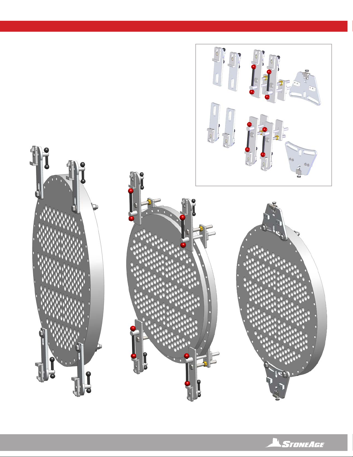
CLAMP SELECTION
Is dependent upon the heat exchanger geometry, bolt holes, hole spacing,
and ange accessibility.
QUICK CLAMPS
Use if heat exchanger ange provides a robust clamping surface or if
ange holes are inaccessible. Align clamps on the surface of the ange to
maximize ange engagement to clamps. (Figure 2)
SLOTTED QUICK AND PLATE CLAMPS
Use if heat exchanger ange has bolt holes that are easily accessible.
Use quick clamps or plate clamps, depending on the spacing of the hole
pattern. (Figures 1 & 3)
SLOTTED QUICK
CLAMP
QUICK CLAMP
PLATE CLAMP
CLAMP TYPES
FIGURE 1 FIGURE 2 FIGURE 3
LIGHTWEIGHT POSITIONER CLAMP SELECTION

10 866-795-1586 • WWW.STONEAGETOOLS.COM
1. Mount the appropriate frame Positioner Clamps to the tube
bundle as shown on the previous page. (Shown in Figure
1 with Slotted Quick Clamps) Positioner Clamps should be
aligned horizontally with the direction of the tube rows. (Figure
1)
NOTE: Heat exchanger tube bundle face, shown for
graphic representation only. Not included in assembly.
2. Insert the Top Rail (slots facing out) into the upper mounting
brackets. If the rail is not closely aligned with the tube rows,
loosen one of the upper mounting brackets and adjust until
the top rail is parallel with the horizontal tube rows. Tighten the
clamps securing the rail to the mounting brackets, and ensure
upper mounting brackets are securely clamped or bolted to
the tube bundle ange. (Figure 2)
3. Insert the Lower Rail (non-slotted) into the lower mounting
brackets. It is not critical that this rail is aligned as precisely as
the top rail, but it should be close to parallel with the top rail for
best performance. Tighten the clamps securing the rail to the
mounting brackets, and ensure lower mounting brackets are
securely clamped or bolted to the tube bundle ange. (Figure
3)
4. Loosen the Quick Adjust Handle and pull the gearbox away
from the carriage plate. This will allow the Horizontal Drive
Carriage to slide onto the rail without pneumatic power to
rotate the drive. Center the carriage on the top rail and push
the gearbox back toward the carriage plate. This will engage
the gear into the rail slots. Verify the gear is engaging the slots
correctly and retighten the adjustable handle. (Figure 4)
LIGHTWEIGHT POSITIONER STEP BY STEP SET-UP
LIGHTWEIGHT POSITIONER SET-UP
FIGURE 1
FIGURE 2
FIGURE 3
FIGURE 4

11
866-795-1586 • WWW.STONEAGETOOLS.COM
5. Slide the Idler Carriage onto the Lower Non-Slotted Rail.
(Figure 5)
6. Loosen the Large Adjustable Handle for the Vertical Rail
Clamp.Align the Idler Carriage with the vertical rail clamp on
the horizontal carriage. Install the Vertical Rail with (slots
facing out) down through the horizontal carriage clamp
and between the rollers on the idler carriage. Adjust the
position of the vertical rail as required and secure the clamp
on the horizontal carriage by tightening the large adjustable
handle. (Figure 6)
7. Loosen the Quick Adjust Handle and pull the gearbox
away from the carriage plate. This will allow the Vertical
Drive Carriage to slide onto the rail without pneumatic
power to rotate the drive. Center the carriage on the vertical
rail and push the gearbox back toward the carriage plate.
This will engage the gear into the rail slots. Verify the gear
is engaging the slots correctly and retighten the adjustable
handle. (Figure 7)
8. Install the four Rail Stops at both ends of the top, slotted,
horizontal rail, and both ends of the vertical slotted rail.
(Figure 8)
NOTE: Verify the mounting brackets and rail clamps
are securely tightened and that the drive carriages
are securely engaged and the adjustable handles are
tightened.
Never loosen the vertical gearbox once the guide
assembly and tractor are installed, as it may result in the
carriage falling vertically down. This may cause damage
and/or injury.
LIGHTWEIGHT POSITIONER SET-UP
FIGURE 5
FIGURE 6
FIGURE 7
FIGURE 8

12 866-795-1586 • WWW.STONEAGETOOLS.COM
COLLET REFERENCE
GUIDE
COLLET
(MULTIPLE SIZES)
HOSE STOP CLAMPS
(MULTIPLE SIZES)
GUIDE TUBES
(MULTIPLE SIZES)
MOUNTING
BRACKET
PITCH ADJUST KNOB
QUICK RELEASE PIN
GUIDE TUBE
ADAPTER SCREWS
TUBE CLAMP
HOUSING
GUIDE ASSEMBLY
GUIDE ASSEMBLY - OVERVIEW

13
866-795-1586 • WWW.STONEAGETOOLS.COM
GUIDE ASSEMBLY
1. Select the appropriate Guide Tube size and length for the
application. The length of the Guide Tubes for an exchanger
bundle with no channel head is 12.5 in. (318 mm). The guide
tube assembly has approximately 5 in. (127 mm) of adjustment.
A deeper channel head will require extended Guide Tubes.
The depth of the channel head added to the 12.5 in. (318 mm)
length will give the desired tube length. Longer guide tubes
are available if required for use with channel heads. Note: The
Banshee tool should not have excessive clearance if the correct
length Guide Tube size is used.
2. To remove the existing Guide Tubes, loosen the Tube Clamp
Bolt and the two 3/16 in. Socket Head Cap Screws (SHCS)
located on top of the Guide Assembly. After selecting the
appropriate guide tubes, install the Guide Tubes into the Guide
Assembly.
3. Secure the Guide Tubes by tightening the two 3/16 in. SHCS.
2
1
3
*NOTE: BN9.5 guide tubes ( Ø.625 in. / 6 mm O.D.) require
an ABX 114 adapter. BN18 guide tubes require an ABX 124
to be installed into the Guide Assembly.
WARNING
Appropriate size Collet selection is critical to ensuring proper
backout prevention of the tool.
GUIDE ASSEMBLY SET-UP
StoneAge (SA) PART NUMBER
COLLET REFERENCE CHART
SA PART NUMBER COLLET SIZE
ABX 121-297 .297 in. / 8 mm
ABX 121-328 .328 in. / 8 mm
ABX 121-406 .406 in. / 10 mm
ABX 121-438 .438 in. / 11 mm
ABX 121-460 .460 in. / 12 mm
ABX 121-484 .484 in. / 12 mm
ABX 121-516 .516 in. / 13 mm
ABX 121-547 .547in. / 14 mm
ABX 121-594 .594 in. / 15 mm
ABX 121-625 .625 in. / 16 mm
StoneAge (SA) PART NUMBER
GUIDE TUBE REFERENCE CHART
SA PART NUMBER SA TOOL INSIDE DIAMETER, LENGTH
ABX 115-12 *BN9.5 .459 in / 12 mm, 12.5 in. / 318 mm
ABX 115-36 *BN9.5 .459 in / 12 mm, 36 in. / 914 mm
ABX 116-12 BN13 .546 in / 14 mm, 12.5 in. / 318 mm
ABX 116-36 BN13 .546 in / 14 mm, 36 in. / 914 mm
ABX 117-12 BN15 .674 in / 17 mm, 12.5 in. / 318 mm
ABX 117-36 BN15 .674 in / 17 mm, 36 in. / 914 mm
ABX 119-12 *BN18 .745 in / 19 mm, 12.5 in. / 318 mm
ABX 119-36 *BN18 .745 in / 19 mm, 36 in. / 914 mm
StoneAge (SA) PART NUMBER
HOSE STOP CLAMP REFERENCE CHART
SA PART
NUMBER HOSE DIAMETER
HS 121-27-34 .27-.34 in. / 7-9 mm
HS 121-34-42 .34-.42 in. / 9-11 mm
HS 121-42-50 .42-.50 in. / 11-13 mm
HS 121-50-56 .50-.56 in. / 13-14 mm
HS 121-56-61 .56-.61 / 14-16 mm

14 866-795-1586 • WWW.STONEAGETOOLS.COM
1
2
GUIDE ASSEMBLY TO LIGHTWEIGHT POSITIONER SET UP
ATTACH GUIDE ASSEMBLY TO LIGHTWEIGHT POSITIONER
1. Using a 9/16 in. wrench, loosen all four rail clamp bolts located on the vertical carriage. Install the Guide Assembly into the rail
clamps and adjust position until the Guide Tubes are approximately 1/2 in. (13 mm) away from the tube sheet face. Tighten the
four rail clamp bolts.
2. Turn the pitch adjustment knob until the guide tubes are at the same pitch as the tubes in the bundle. Adjust the Tube Clamp
Bolt until the Guide Tubes are resting in the bottom of the “V” blocks. Make any ne adjustment to the Guide Tube pitch if
required and tighten the Tube Clamp Bolt.
NOTE: Over-tightening the Tube Clamp may damage thin wall guide tubes.
ABX 114 ADAPTER FOR BN9.5
( Ø.625 in. / 6 mm O.D.)
Guide Tubes
ABX 124 ADAPTER FOR BN18
( Ø.875 in. / 22 mm O.D.)
Guide Tubes
NOTE:
Adjust position until
the Guide Tubes are
approximately 1/2 in.
(13 mm) away from the
tube sheet face.

15
866-795-1586 • WWW.STONEAGETOOLS.COM
AUTOBOX®(ABX-2L) HOSE TRACTOR
HANDLE
FORWARD
AND REVERSE
SPEED
CONTROLS
DOOR PIN
COLOR CODED
JIC FITTINGS
WITH DUST CAPS
MOUNTING
BRACKET
FOR GUIDE
ASSEMBLY
MOUNTING
BRACKET
DRIVE ROLLERS
DOOR
PNEUMATIC SUPPLY LINES
25 FT / 7620 mm
ABX-2L HOSE TRACTOR - OVERVIEW

16 866-795-1586 • WWW.STONEAGETOOLS.COM
DOOR
Always run the ABX-2L Hose Tractor with the doors closed and locked.
DOOR PIN
The Door Pin is a spring plunger with a pull ring. To unlock the door, pull and twist the pull
ring, then release it so that it is no longer in the groove. Close the door by raising it into
position. To lock the door, pull and twist the pull ring, then release it into the groove of the pin.
NOTE: Make sure to lock both doors on each side of the Hose Tractor before operating
ABX-2L Hose Tractor.
LOCKED
UNLOCKED
DOOR
PIN DOOR
PINS
CLOSED DOOR
POSITION
OPEN DOOR
POSITION
ABX-2L HOSE TRACTOR - DOORS & PIN

17
866-795-1586 • WWW.STONEAGETOOLS.COM
WARNING
Always de-energize the system before servicing or replacing any parts. Failure to do so can result in severe injury and/or death.
Keep hands, hair, and clothing clear of rotating parts.
TO REPLACE THE DRIVE ROLLERS:
1. Select the correct roller size for the particular hose being used:
• ABX 271 (DARK GRAY/BLACK) rollers should be used with 5 mm and 6 mm I.D. hoses.
The O.D. range for the ABX 271 roller is .44-.50 in (11 mm - 13 mm)
• ABX 272 (ORANGE) rollers should be used with 3 mm and 4 mm I.D. hoses.
The O.D. range for the ABX 272 is .27-.41 in (7 mm - 10 mm)
2. Slowly run the Drive Rollers in order to orient the key ways of the Drive Rollers upward and the spring plungers downward.
NOTE: Rollers should be removed with the keyway facing up to prevent losing keys.
3. Use a small common screwdriver or similar tool to depress the ball spring plunger, and pull the rollers straight out from the shafts.
4. Prior to reinstalling the Drive Rollers onto the shafts, apply a liberal coat of Anti-seize to the shaft OD and keys.
We recommend Mariners Choice Never-Seez®.
5. Reinstall the rollers by sliding into place until the spring plungers snap out.
NOTE: Rollers should be installed with the keyway facing up to prevent losing keys.
6. Once the correct rollers are installed, close and lock the doors. The Hose Tractor can now be installed onto the Guide Assembly.
ABX 271 (DK GRAY/BLACK)
DRIVE
ROLLERS (X6)
ABX 272 (ORANGE)
SPRING PLUNGER
ORIENTATION
KEY WAY
ABX-2L HOSE TRACTOR - DRIVE ROLLERS

18 866-795-1586 • WWW.STONEAGETOOLS.COM
ATTACH ABX-2L HOSE TRACTOR TO GUIDE ASSEMBLY
1. Remove the lower quick release pin from the ABX-2L Hose Tractor.
2. Slide the mounting bracket over the block on the Guide Assembly and lay the pin onto the top slot on the Guide Assembly block.
3. Install the lower pin through the mounting bracket on the Hose Tractor and the block on the Guide Assembly.
1
3
2
The tractor is now
securely mounted to the
Guide Assembly
ABX-2L HOSE TRACTOR TO GUIDE ASSEMBLY
19
866-795-1586 • WWW.STONEAGETOOLS.COM
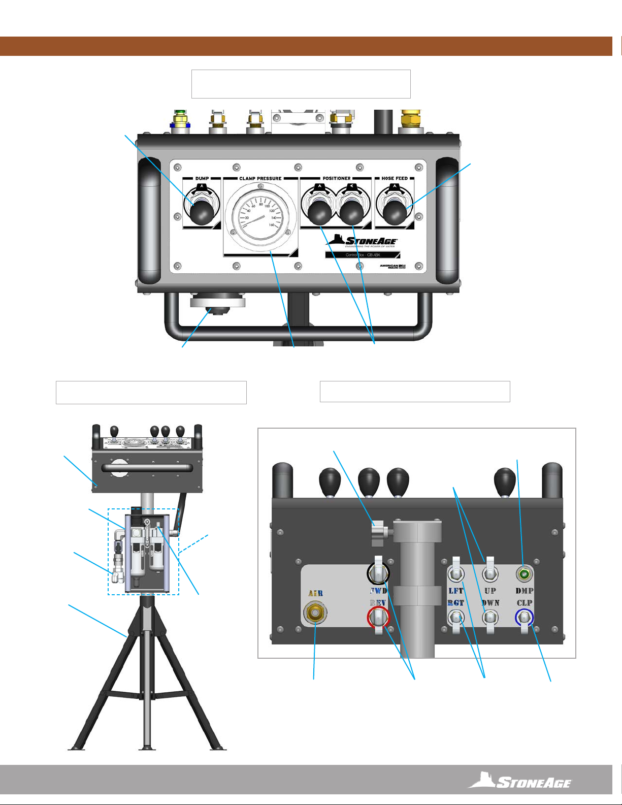
AIR SUPPLY
FITTING
WITH DUST CAP
1/4” (6.35 mm) PUSH CONNECT
PNEUMATIC DUMP
CONTROL FITTING
INLET AIR
FITTING
TRIPOD
LEGS
PRESSURE
REGULATOR
MAIN BOX
FRAME
COLOR CODED
JIC FITTING
WITH DUST CAP
COLOR CODED
JIC FITTINGS
WITH DUST CAPS
VERTICAL
POSITIONER
FITTINGS
WITH DUST CAPS
POLE MOUNT
WITH THUMB SCREW
HORIZONTAL
POSITIONER
FITTINGS
WITH DUST CAPS
HOSE FEED
LEVER
HOSE CLAMP
PRESSURE REGULATOR
HOSE CLAMP
PRESSURE GAUGE
POSITIONER
CONTROLS
MOMENTARY
PNEUMATIC
DUMP CONTROL
INLINE OILER
FEED
ADJUSTMENT
FILTER,
REGULATOR,
LUBRICATOR
CONTROL BOX
FRONT VIEW
CONTROL BOX
TOP VIEW
CONTROL BOX
REAR VIEW
CONTROL BOX - OVERVIEW

20 866-795-1586 • WWW.STONEAGETOOLS.COM
THUMBSCREW
KNOB
TUBE
INSERT
THUMBSCREW
KNOB
(ALIGN WITH
PRE-DRILLED
HOLE ON
TUBE INSERT)
THUMBSCREW
KNOB
(ALIGN WITH
PRE-DRILLED
HOLE ON
TUBE INSERT)
FILTER, REGULATOR,
LUBRICATOR, ASSEMBLY
(FRL)
2
1
3
5
4
CONTROL BOX SET-UP
ASSEMBLE CONTROL BOX, FRL, AND TRIPOD BASE
1. Setup the tripod base in a location with good visibility to the
bundle face, but at a safe distance away from waterblast zone.
2. Slide the vertical tube into the tripod base. Secure with the
supplied thumbscrew knob. Note: The vertical tube has a hole
through one wall that the thumbscrew must engage.
3. Slide the Filter, Regulator, Lubricator (FRL) assembly over the
vertical tube down to the tripod base. Secure with the supplied
thumbscrew knob.
Note: The vertical tube has a hole through one wall that
the thumbscrew must engage.
4. Slide the Control Box over the vertical tube. The Control Box
has a stop that keeps it located at the top of the vertical tube.
Secure with the supplied thumbscrew knob.
5. Install and tighten the short 1/2 in. (13 mm) I.D. hose between
the FRL and the Control Box.
Table of contents
Other StoneAge Industrial Equipment manuals


 User manual")


