StoneAge AUTOBOX ABX-3L-V3 User manual

AUTOBOX® TRACTOR (ABX-3L-V3)
LIGHTWEIGHT POSITIONER (LWPS-100-NS)
& CONTROL BOX (CBX-ABX-PL)
USER MANUAL
PL 702 REV D
(04/2022)

2866-795-1586 • WWW.STONEAGETOOLS.COM
MANUFACTURER’S INFORMATION................................................................ 3
SPECIFICATIONS ........................................................................................ 3
DESCRIPTION OF EQUIPMENT AND INTENDED USE ................................... 3
KEY FEATURES........................................................................................... 3
EC AND UKCA DECLARATIONS OF CONFORMITY....................................... 4-5
WARNING AND SAFETY INSTRUCTIONS ....................................................... 6
OPERATOR TRAINING................................................................................. 6
PERSONAL PROTECTIVE EQUIPMENT REQUIREMENTS.............................. 6
SAFETY LABEL DEFINITIONS....................................................................... 6
PRE-RUN SAFETY CHECK .......................................................................... 7
SYSTEM ASSEMBLY - OVERVIEW .................................................................. 8
LIGHTWEIGHT POSITIONER - OVERVIEW ..................................................... 9
LIGHTWEIGHT POSITIONER CLAMP SELECTION......................................... 10
LIGHTWEIGHT POSITIONER SET-UP............................................................ 11
SHOTGUN MOUNT ..................................................................................... 12
GUIDE ASSEMBLY - OVERVIEW ..................................................................... 14
GUIDE ASSEMBLY SET-UP .......................................................................... 15
GUIDE ASSEMBLY TO LIGHTWEIGHT POSITIONER SET UP ......................... 16
AUTOBOX®(ABX-3L-V3) HOSE TRACTOR - OVERVIEW ................................ 17
AUTOBOX®(ABX-3L-V3) HOSE TRACTOR DRIVE BELT................................. 17
AUTOBOX®(ABX-3L-V3) HOSE TRACTOR TO GUIDE ASSEMBLY ................. 18
CONTROL BOX - OVERVIEW........................................................................... 19
CONTROL BOX SET-UP............................................................................... 20
CONTROL BOX AIR SUPPLY FITTING ............................................................. 21
CONTROL BOX TO AUTOBOX®(ABX-3L-V3) HOSE TRACTOR...................... 22
OPERATION...................................................................................................... 23
AUTOBOX®(ABX-3L-V3) HOSE TRACTOR DOORS AND PINS ...................... 23
COLLET INSERTION, HOSE, AND HOSE STOP INSTALLATION ..................... 24
CONTROL BOX AND HIGH PRESSURE HOSE.............................................. 25
TEST RUN, AND RUN PROCEDURES AND HOSE CLAMP ............................ 26
MAINTENANCE AND STORAGE, TRANSPORTATION, AND HANDLING ..... 27
ABX-3L-V3 BELT REPLACEMENT INSTRUCTIONS .......................... 28
PARTS DIAGRAMS ............................................................ 29
TERMS AND CONDITIONS.................................................... 46
WARRANTY INFORMATION................................................... 47
TABLE OF CONTENTS

3
866-795-1586 • WWW.STONEAGETOOLS.COM
MANUFACTURER’S INFORMATION
DESCRIPTION OF EQUIPMENT AND INTENDED USE
The AUTOBOX® ABX-3L-V3 base system consists of a
Hose Tractor, Control Box, Guide Assembly, and Lightweight
Positioner. This system was developed for “Hands Free” heat
exchanger tube cleaning applications. It is recommended
it be used with the StoneAge® Banshee line of self-rotary
waterblast tools.
The AUTOBOX® ABX-3L-V3 system was designed to
accommodate up to three simultaneous ex lances ranging
in size from 3/2 to 8/4 matched with the appropriate BN9.5,
BN13, BN15, or BN18 size Banshee.
The tractor utilizes a heavy-duty synchronous belt with a
durable polyurethane cover to control the rate at which the
hoses and Banshee tools are advanced or retracted inside
the tubes.
The guide assembly provides anti-withdrawal protection, and
precise tube pitch adjustment.
The lightweight positioner can be mounted to a variety of
heat exchanger tube bundles and has pneumatic powered
horizontal and vertical drives.
The control box is small and lightweight with an emphasis
on ergonomics. The AUTOBOX® ABX-3L-V3 system was
designed with simplicity, lightweight components, durability,
and reliability in mind. It can be easily carried to the job site
and setup in minutes.
SPECIFICATIONS
ABX-3L-V3 TRACTOR Imperial Metric
Weight 48 lbs 22 kg
Dimensions 8.3 x 8.2 x 16.9 in. 211 x 208 x 429 mm
Feed Rate: dependent upon application and hose size 0.3 - 3.0 ft/sec 91 - 914 mm/sec
Push/Pull Force 15 -150 lbs (5-75 lbs per lance) 7-68 kg (2-23 kg per lance)
System Air Consumption 50 cfm at 100 psi 1416 lpm at 6,8 bar
Manway Access: 18 in. 457 mm
CBX-ABX CONTROL BOX
Weight Includes Control Box, FRL, and stand 48 lbs 22 kg
Dimensions 44 x 19 x 19 in
(25 in. diameter foot print)
1114 x 492 x 492 mm
(628 mm. diameter foot print)
Maximum Air Supply Pressure: 125 psi 8,6 bar
System Operating Pressure: 100 psi 6,8 bar
Recommended Operational Temperature Range: -20 ° to 140 °F -29 ° to 60 °C
LIGHTWEIGHT POSITIONER
Weight: Includes 6ft rails, horiz. and vert. idler carriages, and 4 clamps 120 lbs 54.4 kg
HI-VIZ GUIDE ASSEMBLY
Weight: With Guide Tubes 9.5 lbs 4 kg
Without Guide Tubes 6 lbs 3 kg
Pitch Adjustment Range (Dual) 5/8 - 2.5 in. 16 - 64 mm
Pitch Adjustment Range (Triple) 5/8 - 5.0 in. 16 - 127 mm
This manual must be used in accordance with all applicable national laws. The manual
shall be regarded as a part of the machine and shall be kept for reference until the nal
dismantling of the machine, as dened by applicable national law(s). Updated manuals
can be downloaded at: https://www.stoneagetools.com/manuals
StoneAge Inc.
466 S. Skylane Drive
Durango, CO 81303, USA
Phone: 970-259-2869
Toll Free: 866-795-1586
www.stoneagetools.com
StoneAge NL
Reedijk 7Q
3274 KE Heinenoord
Netherlands
(+31) (0) 85 902 73 70
StoneAge UK
Unit 3
Crucible Business Park
Woodbury Lane
Norton
Worcester
Worcestershire, WR5 2DQ
United Kingdom
+44 (0) 1684 892065
KEY FEATURES:
Hose Tractor (ABX-3L-V3)
• Heavy-duty 75mm wide drive belt with steel tension members
• Drive belt has durable polyurethane cover to ensure traction in all
operation conditions
• Can run any hose size from 3/2 to 8/4 without any component changes.
• Can be used in dual or single lance applications
• Quick pin attachment to guide assembly
• Hinged side doors for easy access to belt and drive components
• Independent forward/reverse speed controls
Control Box (CBX-ABX-PL)
Ergonomic design that includes a portable stand and lter-regulator-lubricator assembly
• Tractor controls: forward/reverse hose feed, feed motor pressure selector, and
clamp pressure
• Positioner controls: left/right and up/down
• Pneumatic dump control switch
Lightweight Positioner (LWPS-100-NS)
• Modular, lightweight design with quick install drive carriages
• Utilizes 2.5 in. (64 mm) box rail
• Stainless Steel air motors
• Variety of clamp and bolt-on attachment options are available
Guide Assembly (ABX-301)
• Quick change guide tubes
• 17-4 SS hose stop collets

4866-795-1586 • WWW.STONEAGETOOLS.COM
EC DECLARATION OF CONFORMITY
Manufacturer: StoneAge Incorporated
466 South Skylane Drive
Durango, CO 81303
USA
Authorized Representative: StoneAge Netherlands BV
Reedijk 7Q
3274 KE Heinenoord
Netherlands
Bob Van Wordragen, Operations Manager StoneAge NL
Declare that: AutoBox® Hose Tractor (ABX-3L-V3) and Control Box (CBX-ABX-PL)
for high pressure water cleaning of system parts.
Are compliant with the following Directives and Standards:
Directive 2006/42/EC (Machinery Directive)
EN ISO 12100:2010 (E) Safety of machinery – General principles for design – Risk assessment and risk reduction
The Technical File for AutoBox® Hose Tractor (ABX-3L-V3) and Control Box (CBX-ABX-PL) is maintained at:
StoneAge Incorporated, 466 South Skylane Drive, Durango, CO 81303, USA and was compiled by the Engineering Manager.
The Technical File is available through the Authorized Representative.
This Declaration of Conformity is issued under the exclusive responsibility of StoneAge Incorporated.
________________________________________ 11/20/2021
StoneAge Incorporated, Durango, CO, USA Date
Scott Howell, New Product Introduction Manager

5
866-795-1586 • WWW.STONEAGETOOLS.COM
UK DECLARATION OF CONFORMITY
Manufacturer: StoneAge Incorporated
466 South Skylane Drive
Durango, CO 81303
USA
Authorized Representative: StoneAge UK
Unit 3
Crucible Business Park
Woodbury Lane
Norton
Worcester
Worcestershire, WR5 2DQ
United Kingdom
Steve Ellis, Managing Director StoneAge UK
Declare that: AutoBox® Hose Tractor (ABX-3L-V3) and Control Box (CBX-ABX-PL)
for high pressure water cleaning of system parts.
Are compliant with the following Statutory Requirements and Designated Standards:
S.I. 2008 No. 1597 (E) Safety of machinery – General principles for design – Risk assessment and risk reduction
The Technical File for AutoBox® Hose Tractor (ABX-3L-V3) and Control Box (CBX-ABX-PL) is maintained at:
StoneAge Incorporated, 466 South Skylane Drive, Durango, CO 81303, USA and was compiled by the Engineering Manager.
The Technical File is available through the Authorized Representative.
This Declaration of Conformity is issued under the exclusive responsibility of StoneAge Incorporated.
________________________________________ 11/20/2021
StoneAge Incorporated, Durango, CO, USA Date
Scott Howell, New Product Introduction Manager

6866-795-1586 • WWW.STONEAGETOOLS.COM
OPERATOR TRAINING
Managers, Supervisors, and Operators MUST be trained in Health
and Safety Awareness of High-pressure Water Jetting and hold
a copy the Water Jetting Association (WJA) Code of Practice, or
equivalent (see www.waterjetting.org.uk).
Operators MUST be trained to identify and understand all applicable
standards for the equipment supplied. Operators should be trained
in manual handling techniques to prevent bodily injury.
Operators MUST read, understand, and follow the Operational and
Training Requirements (Section 7.0) of WJTA-IMCA’s Recommended
Practices For The Use Of High-pressure Water jetting Equipment, or
equivalent.
Operators MUST read, understand, and follow the Warnings,
Safety Information, Assembly, Installation, Connection, Operation,
Transport, Handling, Storage, and Maintenance Instructions detailed
in this manual.
StoneAge has designed and manufactured this equipment
considering all hazards associated with its operation. StoneAge
assessed these risks and incorporated safety features in the design.
StoneAge WILL NOT accept responsibility for the results of misuse.
IT IS THE RESPONSIBILITY OF THE INSTALLER/OPERATOR
to conduct a job specic risk assessment prior to use. Job specic
risk assessment MUST be repeated for each different set up,
material, and location.
The risk assessment MUST conform to the Health and Safety at
Work Act 1974 and other relevant Health and Safety legislation.
The risk assessment MUST consider potential material or substance
hazards including:
• Aerosols
• Biological and microbiological (viral or bacterial) agents
• Combustible materials
• Dusts
• Explosion
• Fibers
• Flammable substances
• Fluids
• Fumes
• Gases
• Mists
• Oxidizing Agents
PERSONAL PROTECTIVE EQUIPMENT REQUIREMENTS
Use of Personal Protective Equipment (PPE) is dependent on
the working pressure of water and the cleaning application.
Managers, Supervisors, and Operators MUST carry out a job
specic risk assessment to dene the exact requirements for PPE.
See Protective Equipment for Personnel (Section 6) of WJTA-
IMCA’s Recommended Practices For The Use Of High-pressure
Waterjetting Equipment for additional information.
Hygiene - Operators are advised to wash thoroughly after all
waterjetting operations to remove any waterblast residue which may
contain traces of harmful substances.
First aid provision - users MUST be provided with suitable rst aid
facilities at the operation site.
PPE may include:
• Eye protection: Full face visor
• Foot protection: Kevlar® brand or steel toe capped, water-
proof, non-slip safety boots
• Hand protection: Waterproof gloves
• Ear protection: Ear protection for a minimum of 85 dBA
• Head protection: Hard hat that accepts a full face visor and
ear protection
• Body protection: Multi-layer waterproof clothing approved for
waterjetting
• Hose protection: Hose shroud
• Respiratory protection: May be required; refer to job specic
risk assessment
SAFETY LABEL DEFINITIONS
The AUTOBOX®(ABX-3L-V3) Hose Tractor has the potential to
cause serious injury if ngers, hair, or clothing become caught
between the hose rollers or drive belts. Be sure to head the Hand
Entanglement Roller Labels.
DO NOT OPERATE WITH THE DOORS OPEN. ENSURE THAT ALL
FOUR DOOR PINS ARE SECURED PRIOR TO OPERATION.
Maximum operating air pressure is 100 psi
(6,8 bar). Never exceed 125 psi (8,6 bar)
supply pressure. Exceeding 125 psi (8,6 bar)
supply pressure may result in injury to the
Operator and/or damage to the equipment.
WARNING AND SAFETY INSTRUCTIONS

7
866-795-1586 • WWW.STONEAGETOOLS.COM
WARNING
Operations with this equipment can be potentially hazardous. Caution
MUST be exercised prior to and during machine and water jet tool use.
Please read and follow all of these instructions, in addition to the guide-
lines in the WJTA Recommended Practices handbook, available online
at www.wjta.org. Deviating from safety instructions and recommended
practices can lead to severe injury and/or death.
• Do not exceed the maximum operating pressure specied for
any component in a system.
• The immediate work area MUST be marked off to keep out
untrained persons.
• Inspect the equipment for visible signs of deterioration, dam-
age, and improper assembly. Do not operate if damaged, until
repaired.
• Make sure all threaded connections are tight and free of leaks.
• Users of the AUTOBOX
®
(ABX-3L-V3) Hose Tractor MUST be
trained and/or experienced in the use and application of high
pressure technology and cleaning, as well as all associated safe-
ty measures, according to the WJTA Recommended Practices
for the use of High pressure Water jetting Equipment.
• The Lightweight Positioner must be securely fastened to the tube
bundle, and the Guide Assembly and Tractor must be securely
fastened to the Lightweight Positioner prior to operation.
• An anti-withdrawal device (back-out preventer) MUST be used at
all times. The back-out prevention device is the Hose Stop Collet
located within the Hose Guide Assembly. StoneAge offers sev-
eral different size Hose Stop Collets. The Collet Size Reference
guide is located on the Hose Guide Assembly.
• The Control Box should be located in a safe location where the
Operator has good visibility of the tool entering the exchanger
tubes. The AUTOBOX
®
(ABX-3L-V3) Hose Tractor and Control
Box MUST be supervised at all times and should never be left
unattended.
• Do not fully release the hose clamp (decreasing pressure to zero)
during operation, or the AUTOBOX
®
(ABX-3L-V3) Hose Tractor
will release the hose and may create a dangerous runaway hose
condition, which can result in severe injury and/or death.
• Always de-energize the system before opening the door to
service or replace any parts. Failure to do so can result in severe
injury and/or death.
• When moving the AUTOBOX
®
(ABX-3L-V3) Hose Tractor lift with
care to prevent bodily injury.
• Do not operate the AUTOBOX
®
(ABX-3L-V3) Hose Tractor while
either side door is open.
PRE-RUN SAFETY CHECK
Refer to WJTA-IMCA’s, Recommended Practices For The Use Of High
pressure Waterjetting Equipment and/or The Water Jetting Associa-
tion’s, WJA Code of Practice for additional safety information.
• Complete a job specic risk assessment and act on the resulting
actions.
• Adhere to all site specic safety procedures.
• Ensure the waterblasting zone is properly barricaded and that
warning signs are posted.
• Ensure the work place is free of unnecessary objects (e.g. loose
parts, hoses, tools).
• Ensure all Operators are using the correct Personal Protective
Equipment (PPE).
• Check that the air hoses are properly connected and tight.
• Check all hoses, lances, and accessories for damage prior to use.
Do not use damaged items. Only high quality hoses intended for
waterblast applications should be used as high pressure hoses.
• Check all high pressure threaded connections for tightness.
• **Ensure that an anti-withdrawal device (back-out pre-
venter), whip checks (hose whips), and the appropriate
hose stop collet are installed and set up properly. They
must be veried, secured, tested, and performance con-
rmed before operating at high pressure.**
• Ensure the doors of the AUTOBOX® (ABX-3L-V3) Hose Tractor
are closed and securely latched.
• Test the Control Box before operating the AUTOBOX
®
( A B X - 3 L- V 3 )
Hose Tractor with high pressure water to verify the control valves
move the hose in the intended direction, and that the high pressure
dump valve and hose clamp are working properly.
• Ensure that Operators never connect, disconnect, or tighten hos-
es, adapters, or accessories with the high pressure water pump
unit running.
• Ensure no personnel are in the hydroblasting zone.
WARNING AND SAFETY INSTRUCTIONSWARNING AND SAFETY INSTRUCTIONS

8866-795-1586 • WWW.STONEAGETOOLS.COM
AUTOBOX® (ABX-3L-V3) HOSE TRACTOR,
LIGHTWEIGHT POSITIONER, GUIDE ASSEMBLY,
AND CONTROL BOX (CBX-ABX-PL) SYSTEM ASSEMBLY
CONTROL BOX
(CBX-ABX-PL)
AUTOBOX®
HOSE TRACTOR
(ABX-3L-V3)
HIGH PRESSURE
WATER HOSES
NOT INCLUDED
HOSE STOPS
(HS-121.1-XX)
LIGHTWEIGHT
POSITIONER
(LWPS-100-NS)
GUIDE ASSEMBLY
(ABX-301)
SYSTEM ASSEMBLY - OVERVIEW
NOTICE
Heat exchanger tube bundle face, shown for graphic
representation only. NOT included in assembly.

9
866-795-1586 • WWW.STONEAGETOOLS.COM
SLOTTED QUICK
CLAMP
(LWP 620 KIT
CONTAINS 4)
QUICK CLAMP
(LWP 621 KIT
CONTAINS 4)
PLATE CLAMP
(LWP 622 KIT
CONTAINS 2)
CLAMP TYPES
(LWP 625 KIT IN-
CLUDES ALL KITS
SHOWN HERE)
HORIZONTAL
DRIVE
ASSEMBLY
VERTICAL
SLOTTED RAIL
POSITIONER
CONTROL LINES
25 FT / 7620 mm
STANDARD
LENGTH
VERTICAL
DRIVE
ASSEMBLY
HORIZONTAL
SLOTTED RAIL
SCAFFOLD QUICK CLAMP
(LWP 554-K KIT CONTAINS 4)
LIGHTWEIGHT POSITIONER
AND ACCESSORIES
RAIL STOP
ASSEMBLIES
BLANK HORIZONTAL
ASSEMBLY
RAIL STOP
ASSEMBLY
RAIL EXTENSIONS
(2,4, OR 6 FT LENGTHS)
(.61 m, 1.2 m, OR 1.8 m)
HORIZONTAL
SLOTTED RAIL
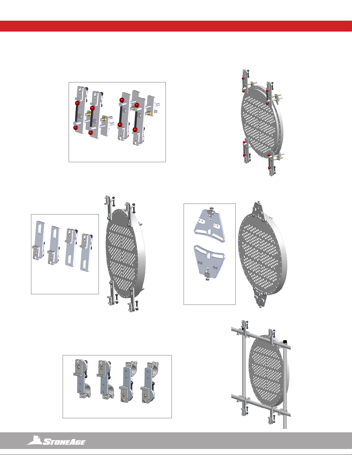
LIGHTWEIGHT POSITIONER - OVERVIEW
10 866-795-1586 • WWW.STONEAGETOOLS.COM
SLOTTED QUICK CLAMP
(LWP 620 KIT CONTAINS 4)
SCAFFOLD QUICK CLAMP
(LWP 554-K KIT CONTAINS 4)
QUICK CLAMP
(LWP 621 KIT CONTAINS 4)
PLATE CLAMP
(LWP 622 KIT
CONTAINS 2)
FIGURE 3FIGURE 2
FIGURE 1
FIGURE 4
LIGHTWEIGHT POSITIONER SET-UPLIGHTWEIGHT POSITIONER CLAMP STYLES
CLAMP SELECTION is dependent upon the heat exchanger geometry, bolt holes, hole spacing, and ange accessibility.
QUICK CLAMPS (LWP 518) are for use with heat exchanger anges that provide a robust clamping surface or if ange holes are inac-
cessible. Align clamps on the surface of the ange to maximize ange engagement to clamps. (Figure 1)
SLOTTED QUICK (LWP 552) AND PLATE CLAMPS (LWP 519) are for use with heat exchanger anges that have easily accessible
bolt holes. Use quick clamps or plate clamps, depending on the spacing of the hole pattern. (Figures 1 & 3)
SCAFFOLD QUICK CLAMPS (LWP 554) are for use with scaffolding in situations
where they may be no way to clamp directly onto the heat exchanger. (Figure 4)

11
866-795-1586 • WWW.STONEAGETOOLS.COM
FIGURE 3
CHECK
Slots Facing
Down
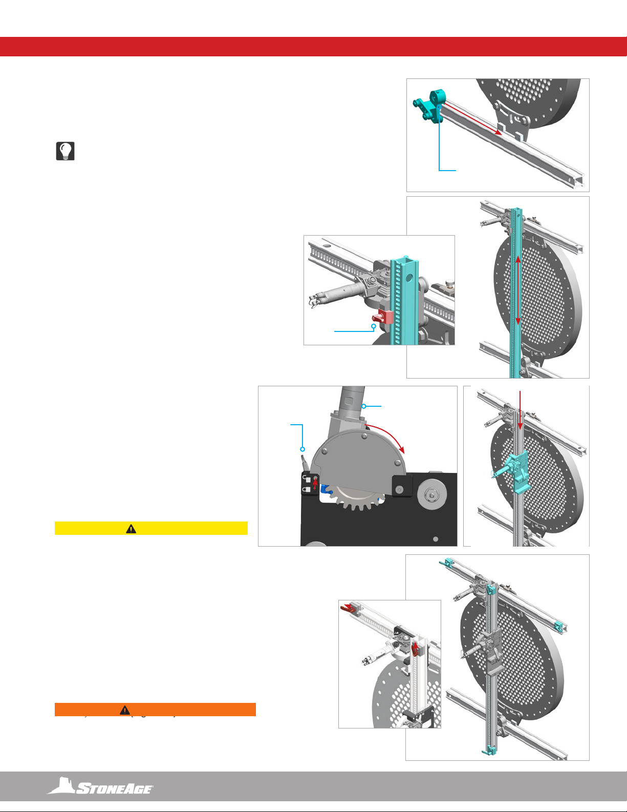
LIGHTWEIGHT POSITIONER STEP BY STEP SET-UP
GEAR
PIN
AIR MOTOR
QUICK RELEASE
UNLOCK
LOCK
FIGURE 4 FIGURE 5
FIGURE 1
FIGURE 2
RAIL CLAMP
TENSIONER
LIGHTWEIGHT POSITIONER SET-UP
NOTICE
Heat exchanger tube bundle face, shown for graphic rep-
resentation only. NOT included in assembly.
CHECK
1. Mount the appropriate frame Positioner Clamps to the tube
bundle as shown in Figure 1. (Shown with Plate Clamps) Po-
sitioner Clamps should be Parallel to the direction of the tube
rows. (Figure 1)
2. Loosen the Rail Clamp Tensioner on the top Positioner
Clamp and insert the Top Rail (slots facing out) into the up-
per rail clamps. Tighten the Rail Clamp Tensioner securing the
rail to the Positioner Clamp. Check Rail Clamp bolts to ensure
they are secured to the tube bundle ange. (Figure 2)
3. Loosen the Rail Clamp Tensioner on the bottom Positioner
Clamp and insert the Lower Rail with the slots facing down,
into the lower rail clamps. It is not critical that this rail is aligned
as precisely as the top rail, but it should be close to parallel
with the top rail for best performance. Tighten the Rail Clamp
Tensioner securing the rail to the Positioner Clamp. Check
Rail Clamp bolts to ensure they are secured to the tube bundle
ange. (Figure 3)
4. Remove the Quick Release Pin from the locked position, pull
back on the air motor to
lift the gear, and insert the
Quick Release Pin into the
unlocked position. This will
allow the Horizontal Drive
Carriage to slide onto
the rail without pneumatic
power. Center the carriage
on the top rail, pull out the
Quick Release Pin, let the
gear drop into place and
verify the gear is engaging
the slotted rail correctly.
12 866-795-1586 • WWW.STONEAGETOOLS.COM
FIGURE 9
FIGURE 8
RAIL
CLAMP
HANDLE
GEAR
FIGURE 7
AIR MOTOR
QUICK RELEASE
PIN
LIGHTWEIGHT POSITIONER SET-UP
UNLOCK
LOCK
Replace the Quick Release Pin into the locked
position. (Figures 4 & 5)
5. Angle the Idler Carriage as shown to allow
the Idler Carriage to engage with the lower rail
properly. Rotate it back to the vertical position and
slide it towards the lower Rail Clamp.
(Figure 6)
TECH TIP:
The rail scraper is spring loaded to t closely
against the rail to remove debris ahead of the
idler roller. Pulling up on the rail scraper or tilting
the idler carriage during installation will increase
clearance and simplify installation.
6. Loosen the Rail Clamp Handle on the Horizontal
Drive.Align the Idler Carriage on the lower rail so
the Vertical Rail can slide into it. Slide the Vertical
Rail with (slots facing out) down through the
Horizontal Drive clamp and between the rollers
on the idler carriage. Adjust the position of the
vertical rail as required and secure the rail in place
by tightening the Rail Clamp Handle on the
Horizontal Drive. (Figure 7)
7. Remove the Quick Release Pin from the
locked position, pull back on the air motor to
lift the gear, and insert the Quick Release Pin
into the unlocked position. This will allow the
Vertical Drive Carriage to slide onto the rail
without pneumatic power. Center the carriage
on the vertical rail, pull out the Quick Release
Pin, let the gear drop into place and verify the
gear is engaging the slotted rail correctly. Replace
the Quick Release Pin into the locked position.
(Figures 8 & 9)
8. Loosen the handles on the four Rail Stops and
slide one onto both ends of the top horizontal rail
and both ends of the vertical rail. Rotate all the
handles so they face away from Horizontal and
Vertical Drives (as shown) and ensure that they are
securely fastened. (Figure 10)
CAUTION
Verify the Positioner Clamps and Rail Clamps
are securely fastened and both drive carriages
are securely engaged and the pinned in the
locked position.
Never unlock the vertical drive once the guide
assembly and tractor are installed, as it may
result in the carriage slipping down the vertical
rail and may cause damage and/or injury.
WARNING
Failure to secure the Rail Clamps properly could
result in the carriages driving off the rails. This may
create a hazardous situation resulting in serious
injury or death.
FIGURE 6
RAIL
SCRAPER
13
866-795-1586 • WWW.STONEAGETOOLS.COM
CAUTION
If the Clamp Handle feels too loose or too tight, it
can be adjusted with a 5mm Allen Key.
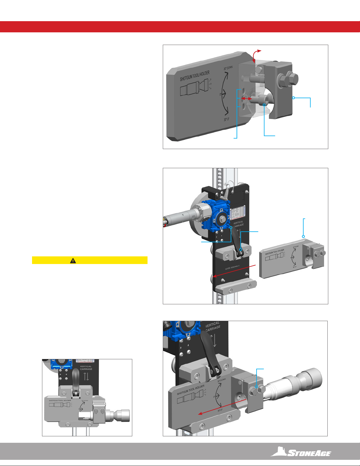
INSTALL SHOTGUN MOUNT
(FOR USE WITH BARRACUDA OR SPITFIRE TOOL)
1. Set the desired Clamp Angle.
• The Clamp Assembly on the Shotgun Mount can
be rotated 30° Up or Down by removing the two
SHCS Screws with a 5/16” Allen Key, rotating
the Clamp into the desired position, and fastening
the Screws in the desired location.
• Make sure these screws are tightened
before operation.
2. Install Shotgun Mount onto the Vertical Carriage.
• Pull to open the Clamp Handle on the Vertical
Carriage and slide the Shotgun Mount in back to
front.
• The mount will stop when it reaches the chamfers
at the front. This is a safety feature.
• Lock the Clamp Handle in place when the mount
is in position.
• Be sure to adjust the tension bolt if necessary
3. Fasten the Shotgun tool in the Clamp.
• Loosen the two Hex Bolts on the Clamp with a
9/16” Hex Wrench.
• Slide the tool in back to front and securely
tighten the Hex Bolts.
CLAMP
ASSEMBLY
INSTALLED
PULL OPEN /
PUSH CLOSED
MOUNTING
POSITIONS
5/16” ALLEN
KEY
TENSION
ADJUSTABLE
WITH 5MM
ALLEN KEY
9/16” HEX
CHAMFER
STOP
OPTIONAL SHOTGUN MOUNT INSTALLATION
14 866-795-1586 • WWW.STONEAGETOOLS.COM
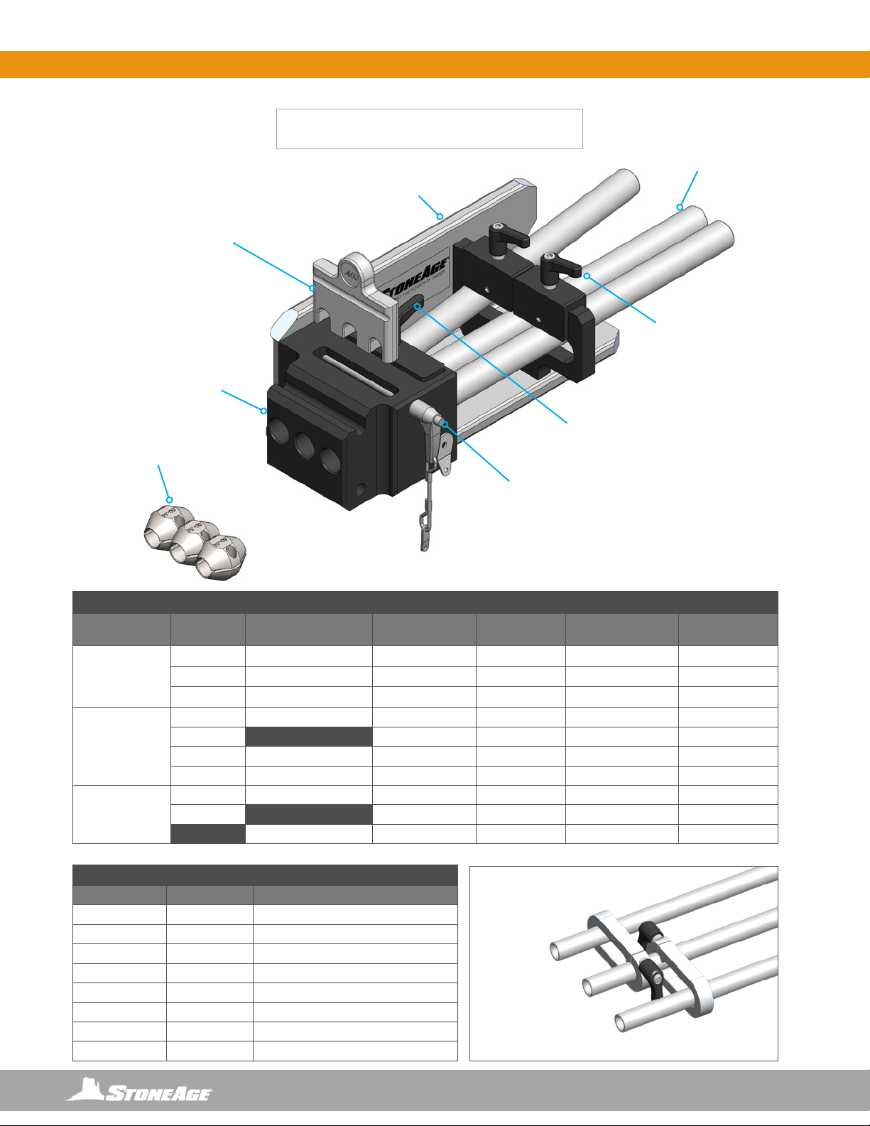
HOSE GUIDE ASSEMBLY - OVERVIEW HOSE GUIDE ASSEMBLY SET-UP
COLLET
(MULTIPLE SIZES
AVAILABLE)
HOSE STOP CLAMPS
(MULTIPLE SIZES AVAILABLE)
GUIDE TUBES
(MULTIPLE SIZES AVAILABLE)
MOUNTING
BRACKET
PITCH ADJUST
LEVERS
QUICK RELEASE PIN
TUBE CLAMP
ALUMINUM
HOUSING
HOSE GUIDE ASSEMBLY
(ABX-301)
StoneAge (SA) PART NUMBER GUIDE TUBE REFERENCE CHART
GUIDE TUBE BANSHEE INSIDE DIAMETER, LENGTH
ABX 115-12 BN9.5 .459 in / 11.7 mm, 12.5 in. / 318 mm
ABX 115-36 BN9.5 .459 in / 11.7 mm, 36 in. / 914 mm
ABX 116-12 BN13 .546 in / 13.9 mm, 12.5 in. / 318 mm
ABX 116-36 BN13 .546 in / 13.9 mm, 36 in. / 914 mm
ABX 117-12 BN15 .674 in / 17.1 mm, 12.5 in. / 318 mm
ABX 117-36 BN15 .674 in / 17.1 mm, 36 in. / 914 mm
ABX 119-12 BN18 .745 in / 18.9 mm, 12.5 in. / 318 mm
ABX 119-36 BN18 .745 in / 18.9 mm, 36 in. / 914 mm
StoneAge (SA) PART NUMBER COLLET AND HOSE STOP REFERENCE CHART
HOSE O.D. SPIR STAR PARKER COLLET SIZE
COLLET PART
NUMBER HOSE STOP SIZE
HOSE STOP
PART NUMBER
.27-.41 in
(7 mm - 10 mm)
3/2 2240D-02 .297 in. / 7.5 mm ABX 171-297 .27-.34 / 7-9 mm HS 121-27-34
3/4, 4/2 2240D-025, 2440D-02 .328 in. / 8.3 mm ABX 171-328 .27-.34 / 7-9 mm HS 121-27-34
3/6, 5/2 2240D-03 .406 in. / 10.3 mm ABX 171-406 .34-.42 / 9-11 mm HS 121-34-42
.44-.50 in
(11 mm - 13 mm)
4/4 2448D-025 .438 in. / 11.1 mm ABX 171-438 .34-.42 / 9-11 mm HS 121-34-42
4/6, 5/4 .460 in. / 11.7 mm ABX 171-460 .42-.50 / 11-13 mm HS 121-42-50
6/2 2240D-04, 2640D-025 .484 in. / 12.3 mm ABX 171-484 .42-.50 / 11-13 mm HS 121-42-50
6/4 2440D-04, 2740D-025 .516 in. / 13.1 mm ABX 171-516 .50-.56 / 13-14 mm HS 121-50-56
.52-.61 in
(13 mm - 16 mm)
5/6, 8/2 2240D-05, 2740D-03 .547 in. / 13.9 mm ABX 171-547 .50-.56 / 13-14 mm HS 121-50-56
5/6H, 8/4 .594 in. / 15.1 mm ABX 171-594 .56-.61 / 14-16 mm HS 121-56-61
2440D-05 .625 in. / 15.9 mm ABX 171-625 .56-.61 / 14-16 mm HS 121-56-61
*OPTIONAL ABX 140-XX GUIDE TUBE
ANTI-TWIST CLAMPS
DESIGNED TO KEEP
PITCH ALIGNMENT
BETWEEN LONGER
GUIDE TUBES
SEE “PART DIAGRAM“
PAGES FOR SIZING.

15
866-795-1586 • WWW.STONEAGETOOLS.COM
HOSE GUIDE ASSEMBLY SET-UP
2
2
1
3
3
HOSE GUIDE ASSEMBLY
1. Select the appropriate Guide Tube size for the application from the chart at the bottom of the previous page.
• The length of the Guide Tubes for an exchanger bundle with no channel head is 12.5 in. (318 mm).
• A deeper channel head will require extended Guide Tubes. The depth of the channel head added to the 12.5 in. (318 mm) length will
give the desired tube length.
• Longer guide tubes are available if required for use with channel heads.
NOTICE
The Banshee tool should not have excessive clearance if the correct Guide Tube size is used.
2. To remove the existing Guide Tubes, loosen the Tube Clamp Lever and the two Pitch Adjust Levers, located on top of the Guide As-
sembly. After selecting the appropriate Guide Tubes, install the Guide Tubes into the Guide Assembly.
3. Secure the Guide Tubes by tightening the Tube Clamp Lever and Pitch Adjust Levers, when the desired pitch has been set.
4. Select the appropriate Collet and Hose Stops from the chart on the previous page and reserve them for future Hose and Collet installa-
tion instructions in this manual.
WARNING
Appropriate size Collet selection is CRITICAL to ensuring proper backout prevention of the tool. Use the chart on the previous page to
select the proper Collet and Hose Stop sizes per hose diameter. Always conrm backout prevention performance before operating the
system at high pressure.
1, 2, or 3 HOSE LOADING POSITIONS
The
AUTOBOX
®
(ABX-3L) Hose Tractor
can be used as a 1, 2, or, 3 Lance tool. The diagrams below show which Guide Tubes to load for
best performance. The numbered positions correspond with the indicator markings on the top of the Hose Tractor and the identiers in the
Controller interface.
SINGLE HOSE LOAD
1 2 3 1 2 3 1 2 3
TRIPLE HOSE LOAD
DUAL HOSE LOAD

16 866-795-1586 • WWW.STONEAGETOOLS.COM
3
2
1
45
Tech Tip:
• When mounting the Guide Tube Assembly make sure to lift
the backside of the Tractor, this will make sure the Guide
Tube Assembly is parallel with the Vertical Carriage.
• Always make sure before operating, to pull down on the
Tractor with both hands and try to pull it back from the
Lightweight Positioner and tilt the back of the Tractor
upwards to make sure there is no play.
• If the Clamp Handle feels too loose or too tight, it can be
adjusted with a 5mm Allen Key. Follow the instructions on the
decal on the Vertical Drive.
ATTACH GUIDE ASSEMBLY TO LIGHTWEIGHT POSITIONER
1. Pull Quick Release Handle open and slide the Guide Tube Assembly onto the Vertical Carriage.
2. Adjust position until the Guide Tubes are approximately 1/2 in. (13 mm) away from the face of the heat exchanger.
3. Lock the Quick Release Handle in place when the mount is in position. Be sure to adjust the tension bolt if necessary.
(See Tech Tip below)
4. Loosen the Pitch Adjustment Levers and adjust the guide tubes until they are in line with pitch of the tubes in the
bundle.
5. Tighten Tube Clamp and Pitch Adjustment Levers until tubes are secured in position.
PULL OPEN /
PUSH CLOSED
TENSION
ADJUSTABLE WITH
5MM ALLEN KEY
HOSE GUIDE ASSEMBLY TO LIGHTWEIGHT POSITIONER SET UP
CAUTION
THE QUICK RELEASE HANDLE ON THE VERTICAL CARRIAGE MUST BE SECURELY FASTENED TO THE GUIDE TUBE ASSEMBLY.
ADJUST THE TENSION ON THE BOLT HANDLE TO ENSURE A SECURE CLAMP ON THE GUIDE TUBE ASSEMBLY. SEE DIAGRAM AT
THE BOTTOM OF THE PAGE.

17
866-795-1586 • WWW.STONEAGETOOLS.COM
HANDLE
DOOR
ASSEMBLY
*DRIVE BELT
MOUNTING
BRACKET
QUICK
RELEASE
PINS
DOOR PIN
QUICK EXHAUST
WITH SILENCER
FORWARD SPEED
CONTROL
COLOR CODED PUSH
CONNECT FITTINGS WITH
DUST CAPS
*ABX 305-50 BELT 50A 10MM (INSTALLED)
ABX 305-80 BELT 80A 25MM (INCLUDED)
PNEUMATIC SUPPLY LINES
(CBL A025F-2PL5)
25 FT / 7620 mm
REVERSE SPEED
CONTROL
MOUNTING BRACKET
FOR GUIDE ASSEMBLY
COLLET
REFERENCE
CHART
ABXS-3L HOSE TRACTOR - OVERVIEW
AUTOBOX®HOSE TRACTOR
(ABX-3L-V3)

18 866-795-1586 • WWW.STONEAGETOOLS.COM
2
3
1
THE TRACTOR IS NOW SECURELY
MOUNTED TO THE GUIDE ASSEMBLY
ABXS-3L HOSE TRACTOR TO GUIDE ASSEMBLY
ATTACH AUTOBOX®(ABX-3L-V3) HOSE TRACTOR TO GUIDE ASSEMBLY
1. Remove the lower quick release pin from the AUTOBOX®(ABX-3L-V3) Hose Tractor.
2. Slide the mounting bracket over the block on the Guide Assembly and lay the pin onto the top slot on the Guide Assembly block.
3. Install the lower pin through the mounting bracket on the Hose Tractor and the block on the Guide Assembly.

19
866-795-1586 • WWW.STONEAGETOOLS.COM
CONTROL BOX
FRONT VIEW
CONTROL BOX
TOP VIEW
CONTROL BOX
BACK VIEW
MOMENTARY
PNEUMATIC
DUMP CONTROL
CONTROL
PANEL BOX
ON/OFF
VALVE
INLET AIR
FITTING
TRIPOD
LEGS
HOSE CLAMP
PRESSURE GAUGE
FILTER,
REGULATOR,
LUBRICATOR
(FRL)
INLINE OILER
FEED
ADJUSTMENT
HOSE CLAMP
PRESSURE
REGULATOR
AIR SUPPLY
FITTING FROM FRL
HOSE FEED
FORCE
POSITIONER
CONTROLS
TRACTOR
FITTINGS
VERTICAL POSITIONER
FITTINGS
HORIZONTAL
POSITIONER FITTINGS
POLE MOUNT
WITH THUMB SCREW
HOSE FEED
LEVER
DUMP CONTROL
FITTING
CLAMP FITTING
CONTROL BOX - OVERVIEW

20 866-795-1586 • WWW.STONEAGETOOLS.COM
CONTROL BOX SET-UP
ASSEMBLE CONTROL BOX, FRL, AND TRIPOD BASE
1. Setup the tripod base in a location with good visibility to the bundle face, but at a safe distance away from high pressure nozzles.
2. Slide the vertical tube into the tripod base. Secure with the supplied thumbscrew knob.
3. Slide the Filter, Regulator, Lubricator (FRL) assembly over the vertical tube down to the tripod base. Secure with the supplied thumbscrew
knob.
4. Slide the Control Box over the vertical tube. The Control Box has a stop that keeps it located at the top of the vertical tube. Secure with
the supplied thumbscrew knob.
5. Install and tighten the short 1/2 in. (13 mm) I.D. hose between the FRL and the Control Box.
5
FILTER, REGULATOR,
LUBRICATOR, ASSEMBLY
(FRL)
2THUMBSCREW
KNOBS
TUBE
INSERT
5
4
1
3
Table of contents
Other StoneAge Industrial Equipment manuals


 User manual")


