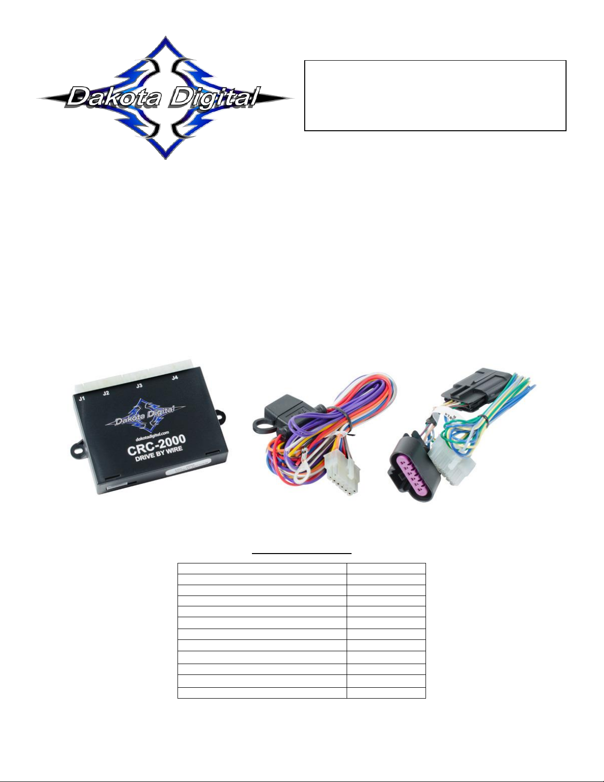
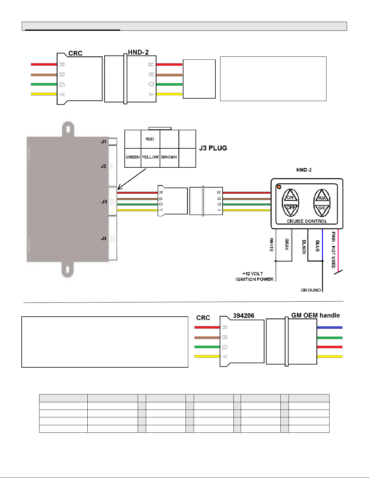
Dakota Digital CRC-2000 User manual
Other Dakota Digital Automobile Accessories manuals

Dakota Digital
Dakota Digital Retrotech RTX-33F User manual

Dakota Digital
Dakota Digital VHX-63F-GAL User manual

Dakota Digital
Dakota Digital Odyssey II Series User manual

Dakota Digital
Dakota Digital VLC-69F-MUS User manual

Dakota Digital
Dakota Digital SGI-8 rev. C User manual

Dakota Digital
Dakota Digital HLY-3073 User manual

Dakota Digital
Dakota Digital VHX-1016 User manual

Dakota Digital
Dakota Digital LED Tail Lights LAT-NR221 User manual

Dakota Digital
Dakota Digital RLC-40F User manual

Dakota Digital
Dakota Digital VHX-1018 User manual

Dakota Digital
Dakota Digital VHX-78C-VTA User manual

Dakota Digital
Dakota Digital CRC-1000 User manual

Dakota Digital
Dakota Digital VHX-84B-REG User manual

Dakota Digital
Dakota Digital Odyssey HLY-1041 User manual

Dakota Digital
Dakota Digital BIM-16-1 User manual

Dakota Digital
Dakota Digital LED Tail Lights for 1968 Chevelle LAT-NR180 User manual

Dakota Digital
Dakota Digital VHX-1023 User manual

Dakota Digital
Dakota Digital Retrotech RTX-70C-CAM User manual

Dakota Digital
Dakota Digital VHX-35F User manual

Dakota Digital
Dakota Digital CMD-1000 User manual