2
D
GB
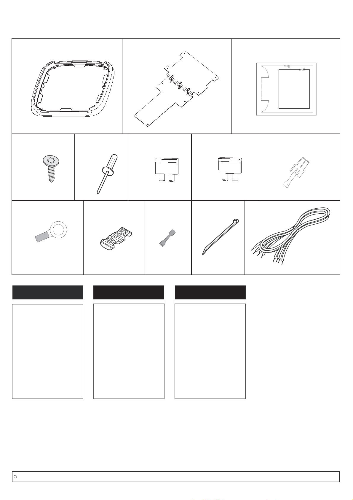
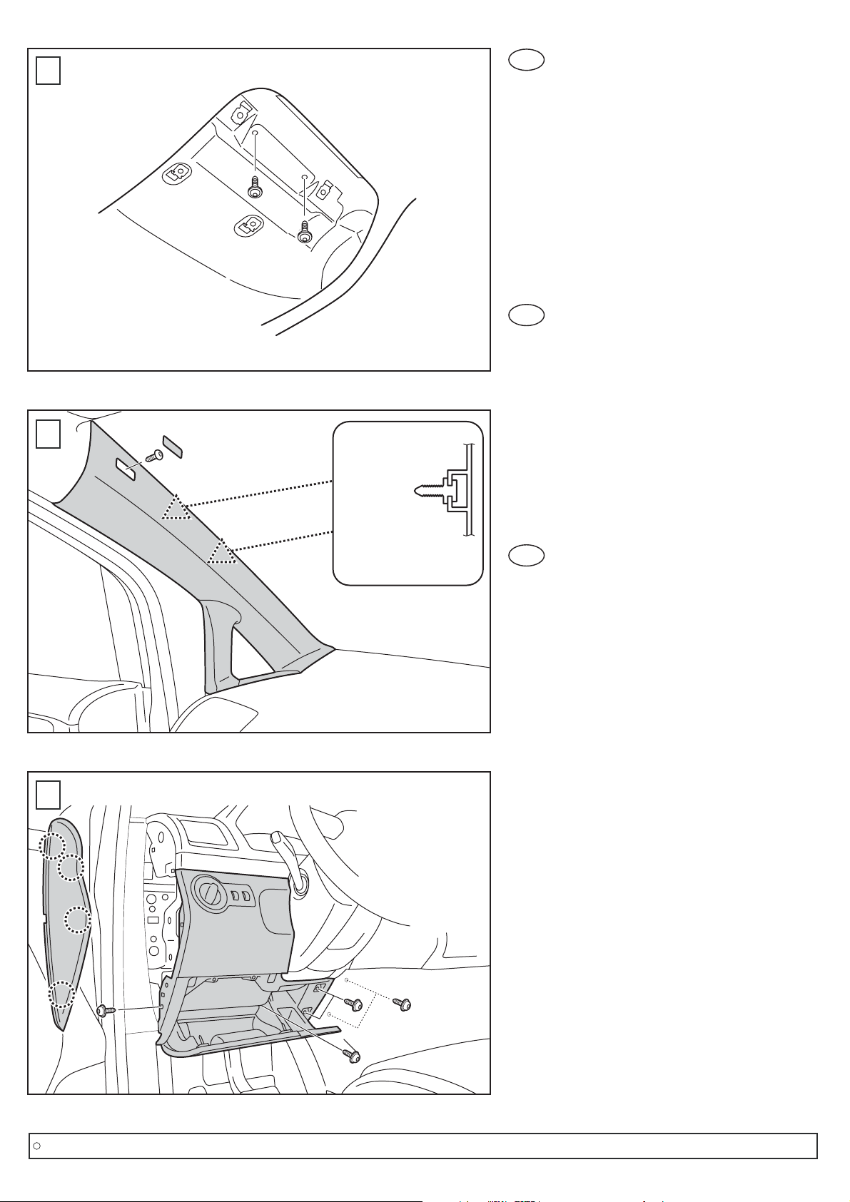
1. Die mitgelieferte Schablone (3) aus-
schneiden, am Himmel positionieren
und mit Kreppband fixieren.
Nach dem Fixieren nochmals nachmessen,
ob die Schablone mittig sitzt.
2. Wie im Bild gezeigt, den inneren Bereich mit
einem geeigneten Messer ausschneiden.
Darauf achten, dass die Dachhaut
oder am Himmel angeklebte Leitungen nicht
beschädigt werden.
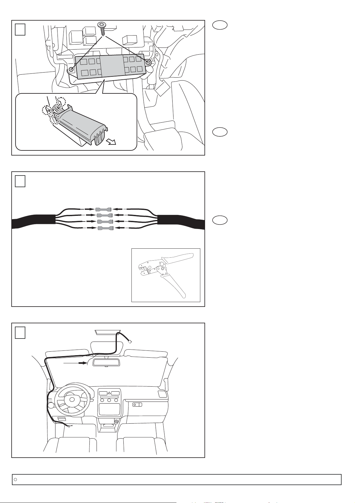
3.
Zuerst die vordere Innenraumleuchten-
Abdeckung ausclipsen, die beiden Torx-
Schrauben entfernen und die Lampeneinheit
herausnehmen. Anschließend alle Fächer
der Konsole öffnen und die 6 Torxschrauben
entfernen.
Die Konsole kann jetzt ausgebaut werden.
Obere Konsole ausbauen
1
3
1. Cut out the provided template (3). Fix the
template with crepe tape. After that check
the right position again.
2. As shown in the picture, cut out the inner
area with a suitable knife.
Be careful not to damage the roofing or the
cable affixed in the roof's interior.
3.
At first unclip the front covering of the
interior lamp. Remove both torx screws and
dismantle the interior lamp. Open all
compartments and remove the remaining 6
torx screws. After that, the console can be
removed.
Dismounting the upper console
FR
1. Caler la platine fournie (3). La fixer à l'aide
de l'adhésif dans le but de vérifier le bon
positionnement de celle-ci.
2. Comme indiqué dans le schéma découper
délicatement la garniture du toit, attention a
ne pas endommager d'éventuels câbles ou
autres composants.
3.
En premier lieu dé-clipper le capot de la
lampe intérieure. Retirer les deux vis torx
puis démonter le plafonnier. Ouvrir tous les
compartiments puis retirer les 6 autres vis
torx. Après cela toute la console peut être
retirée.
Démontage de la console
Copyright MS Design - Autotuning GmbH
C6/13
Montageanleitung/ Mounting instructions/ Instructions de montage