Strand Lighting MX Service manual
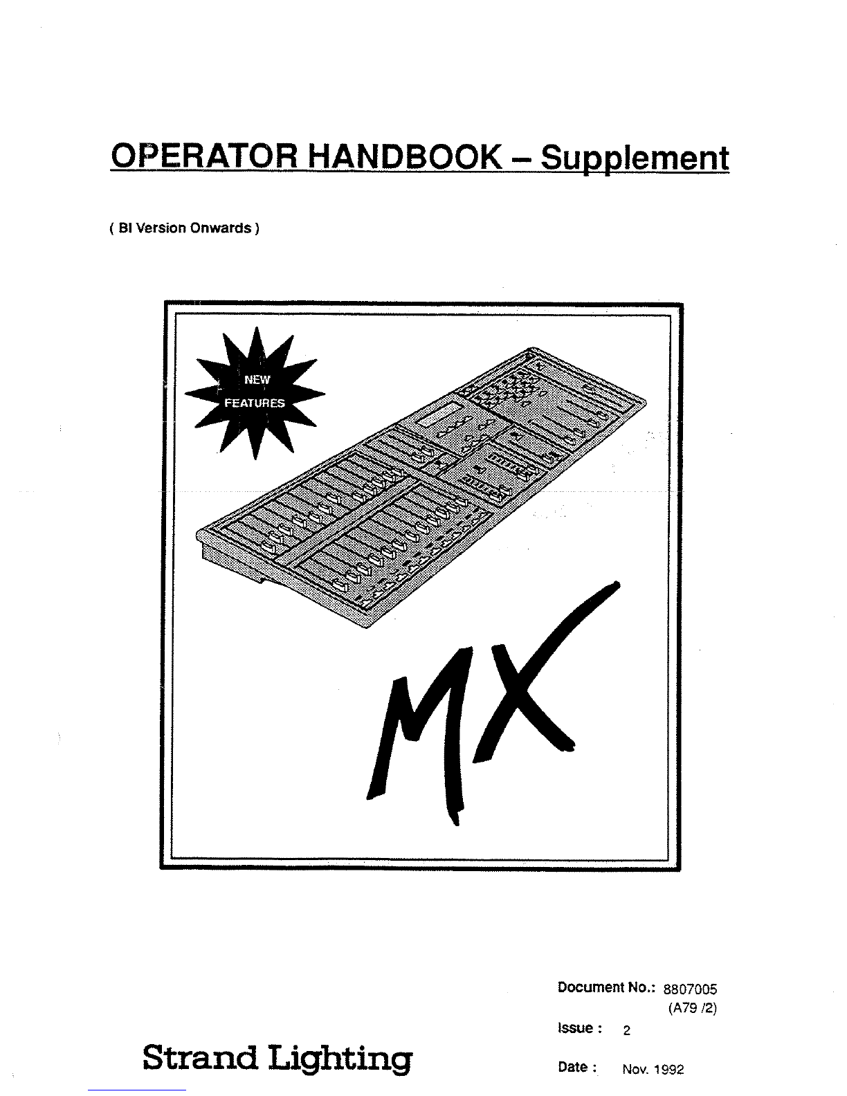
OPERATOR
HANDBOOK
-
Supplement
(
BI
Version
Onwards)
Strand
Lighting
Document
No
. :
8807005
(A79
l2)
Issue
:
2
Date
:
Nov
.
1992
FEATURES
a
~
F
a
aY"
p 4
AV
.
A~
v?
h5
y
'~
r
'
V
Strand
Lighting
Offices
Note
:
Telephone
numbers
exclude
international
and
national
dialling
codes
USA
:
PO
Box
9004,
18111
South
Santa
Fe
Avenue,
Rancho
Dorninguez,
CA
90221
USA
Tel
:
310
637
7500
Fax
:
310
632
5519
Whilst
every
effort
has
been
made
to
ensure
the
completeness
and
accuracy
of
the
information
in
this
handbook,
no
liability
can
be
accepted
for
any
errors
or
omissions
.
Strand
Lighting
Ltd
.
reserves
the
right
to
amend
the
specifications
of
the
product
at
any
time
.
This
document
is
issued
on
condition
that
the
information
contained
herein
is
not
copied,
reprinted,
or
otherwise
duplicated
by
a
third
party
wholly
or
in
part
without
the
consent
in
writing
of
Strand
Lighting
Limited_
Certain
features
of
the
equipment
described
in
this
document
may
form
the
subject
of
patents
or
patent
applications
.
©
Strand
Lighting
Limited
1992
Asia
:
802
Houston
Centre,
63
Mody
Road, Tsimshatsui
East,
Kowloon,
Hong
Kong
Tel
:
368
5161
Fax
:
3694890
Canada
:
2430
Lucknow
Drive,
Unit
15,
Mississauga,
Ontario
LSS
1V3
Canada
Tel
:
416677
7130
Fax
:
416
677
6859
France
:
26
Villa
Des
Fleurs,
92400
Courbewie,
France
Tel
: 1
478
86666
Fax
:
1
433
37175
Germany
:
Salzbergstasse,
3340
Woltenbuttel
Salzdahlum,
Gennany
Tel
:
5331
30080
Fax
:
5331
78383
Italy
:
Via
delle
Gardenia
80
(Pontina
Vecchia
Km
33,400),
00040
Pomezia-Ronsa,
Italy
Tel
:
6
914
7123
Fax
:
6
914
7136
United
Kingdom
:
Grant
Way,
(off
Syon
Lane),
Isleworth,
Middx
.,
TW750D
U
.K
Tel
:
081
560
3171
Fax
:
081
568
2103
Issue 2
MX
SUPPLEMENT
Contents
TERMINAL
DISPLAY
.
.
.
. .
. .
.
. .
.
.....
.
...
. .
.....
.
. .
.
....
.
.....
SP2
Introduction
...
. .
.
. .
... .
.
....
. .
...
.
....
. .
.
.
....
...
.....
.....
2
Connecting
MX
To
The
Terminal
Monitor
.....
.
. .
.
. .
.
....
.
...
.
3
Connecting
MX
To
a
RC
...
. .
...
.
...
.
. .
.
....
.
.....
.
.......
.
.
3
Running
MX
TERM
On
a
PC
......
.
........
.
. .
....
....
.
. .
.
. .
.
3
Setting
Up
MX
for
Terminal Monitor
&
PC
......
. .
.
.
...
. .
. .
.
. .
.
4
Displays
Options
.
...
.
....
....
.
. .
. .
....
.
.
. .
. .
. .
.
. .
.
.
.
.......
5
Menu
Displays
. .
. .
. .
.
.
.
. .
.
.
.....
.
.....
.
.
. .
. .
....
....
....
.
. .
6
Printing
. .
....
....
.....
.
. .
. .
.
.
. .
.
.
.
.
...
.. .....
... .
....
....
8
MIDI
APPLICATIONS
....
.
.....
...
...
.
...
.
. .
.
.... .......
.
....
.
.
SP9
Introduction
. .
.
. .
.
. .
. .
.
.
..........
.
.
.
...
.
....
.
.....
...
......
9
Recording
MX
with
Music
Sequencers
....... .
.
.....
.
....
.
. .
10
SYNC
Function
.
.
.
. .
....
..........
.
. .
.
. .
...
. .
.
.
.
...
....
....
12
Slave
Mode
. .
.
. .
.
. .
. .
.
.
....
.
....
.
. .
.
.......
. .
.....
....
....
13
REMOTE
`GO'
CUE
...
.
...
.
...
...
.
....
.
. .
.
. .
.
....
.
.....
....
.
SP15
Midi'GO'
...
.....
. .
.
.
..
.
.
. .
. .
...
. .
.
.....
. .
. . .
.
.
. .
.....
.
....
15
Audio/Midi
Fader
.
.
. .
. .
. .
....
.
....
.
.
. .
. .
.
....
.
.....
....
....
16
Audio
`GO'
.....
. .
.
.
. .
.
.
. .
. .
...
. .
.
.....
...
. .
.
. .
.
. .
.
. .
.
....
17
MX
SUPPLEMENT
Issue 2
TERMINAL
DISPLAY
Introduction
The
facility
now
exists
to
view
the
output
levels
and
status
modes
of
MX
`at
a
glance'
either directly
via
an
ANSI
terminal
available
from
Strand
Lighting,
or
alternatively
a
Terminal
Emulator
program
is
available
for
any
PC
compatible,
running
any
level
of
DOS,
with
the
option
to
view
in
colour
.
Part
Number
for
the
terminal
and
interface
lead
04900
01
.
Part
Number
for
the
lead only
The
emulator
version
is
a
`display
only' feature
and
involves
no
input
from
the
PC
keyboard
other than
booting
up
and
exiting
.
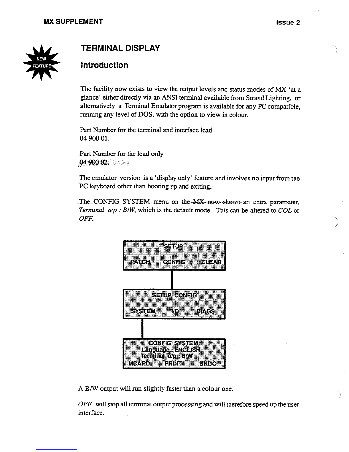
The
CONFIG
SYSTEM
menu
on-
the
MX
now
-shows
an
-extra
parameter,
Terminal
olp
:
BIW,
which
is
the
default
mode
.
This
can
be
altered
to
COL
or
OFF
.
ONFIG
SYSTEM
ang~age
.
.~N1^aL}S
Ie~iaaI
Wp
:
:61t1f1
"
PRINT
[7NDO`
A
B/W
output
will
run
slightly
faster
than
a
colour
one
.
OFF
will
stop
all
terminal
output
processing
and
will
therefore
speedup
the
user
interface
.
Issue
2
MX
SUPPLEMENT
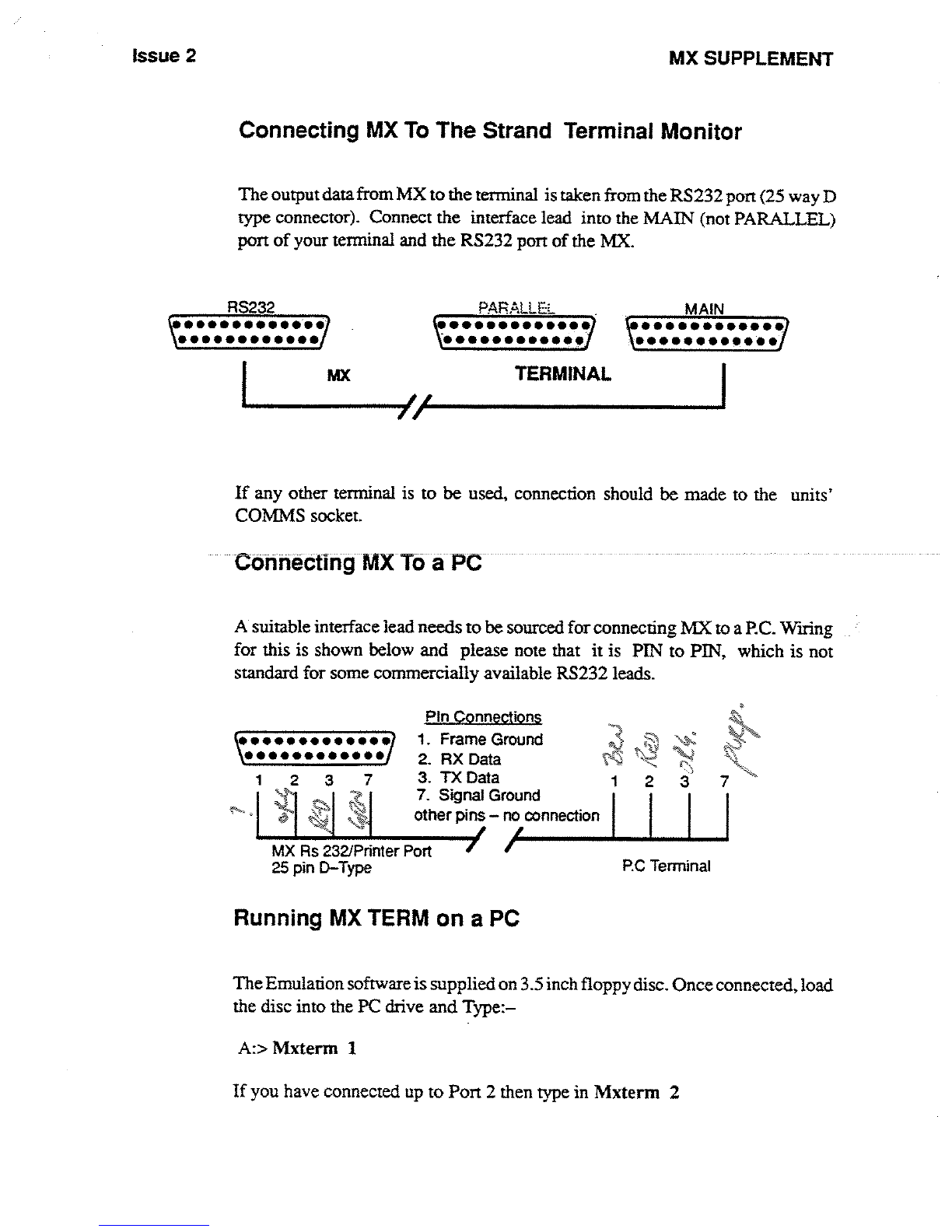
Connecting
MX
To
The
Strand
Terminal
Monitor
The
output
data
from
MX
to the
terminal
is
taken
from
the
RS232
port
(25
way
D
type
connector)
.
Connect
the
interface lead into
the
MAIN
(not
PARALLEL)
port
of
your
terminal
and
the
RS232
port
of
the
MX
.
_
RS232
PARALLE
:
MAIN
690i00099
90
A*66
0s000
*0*0
**0999*600*0
s0*0060600a*
.
TERMINAL
If
any
other terminal
is
to
be
used,
connection
should
be
made
to
the
units'
COMMS
socket
.
Connecting
MX
To
a
PC
-
A
suitable interface
lead
needs
to
be
sourced
for
connecting
MX
to
a
PC
.
Wiring
for
this
is
shown
below
and
please note
that
it is
PIN
to
PIN,
which
is
not
standard
for
some
commercially
available
RS232
leads
.
MX
Rs
232/Printer
Port
25
pin
D-Type
PIn
Connections
1
.
Frame
Ground
2
.
RX
Data
3
.
TX
Data
7
.
Signal
Ground
other
pins
-
no
connection
Running
MX
TERM
on
a
PC
RC
Terminal
A
:>
Mxterm
1
If
you
have
connected
up
to
Port
2 then
type
in
Mxterm
2
The
Emulation
software
is
supplied
on
3
.5
inch
floppy
disc
.
Once
connected,
load
the
disc into
the
PC
drive
and Type
:-
MX
SUPPLEMENT
Issue
2
Setting
Up
Mx
for
Terminal
Monitor
&
PC
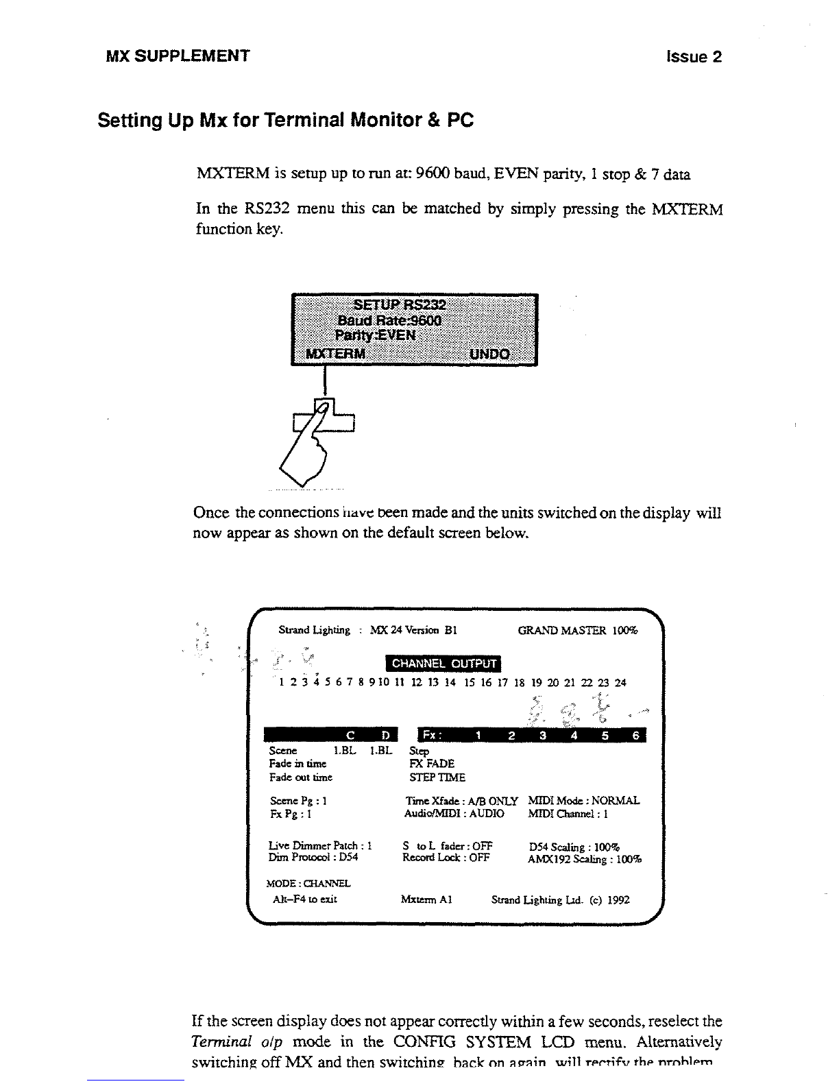
MXTERM
is
setup
up
to
run
at
:
9600
baud,
EVEN
parity,
1
stop
&
7
data
In the
RS232
menu
this
can
be
matched
by simply
pressing
the
MXTERM
function
key
.
Once
the
connections
have
peen
made
and
the
units
switched
on
the display
will
now
appear
as
shown
on
the
default
screen
below
.
Stand
Lighting
:
MX
24
Version
In
GRAND
MASTER
100%
1
234567891011
121314
15161718192021222324
a .
C
D
CHANNEL
OUTPUT
Scene
1
.BL
I
.BL
Step
Fade
in
time
FX
FADE
Fade
out
nine
STEP
TIME
Scene
Pg
:
1
Tune
Xfade
:
AIB
ONLY
MIDIMode
:NORMAL
Fx
Pg
: 1
Audio/M[DI
:
AUDIO
Mn)I
Channel
: I
Live
Dimmer
Patch
:
I
S
to
L
fader
:
OFF
D54
Scaling
:
100go
AMX192
Scaling
:
100%
Dint
Protocol
:
D54
Record
Lock
:
OFF
MODE
:
QIANNEL
Fx
:
1
2
3
4 5 6
Alt-F4
to exit
Mxtenn
A1
Strand Lighting
Ltd
.
(c)
1992
If
the
screen
display
does
not appear
correctly
within
a
few
seconds,
reselect the
Terminal
olp
mode
in
the
CONFIG
SYSTEMLCD
menu
.
Alternatively
switching
off
MX
and
then
switching
hack
on
arrain
will
rr
rtifv
thr
nrnhlrm
Issue
2
MX
SUPPLEMENT
Display
Options
The
following
parameters
are
also
displayed
along
the
MODE
line
if
selected
on
the
desk
:-
CHANNEL
SCENE
HOLD
RECORD
BLACKOUT
FLASHOFF
NUMLOCK
(BLACKOUT
and
RECORD
will
appear
in
inverse
video
when
selected
)
.
If
some
errors
have
occurred
CHECKLOG
will
appear
.
If
effects
are
running,
these are also
displayed
showing
the
CURRENT
STEP,
FADE
TIMES
and
STEP
TIMES
.

MX
SUPPLEMENT
Issue
2
Menu
Displays
When
you
enter
the
SCENE
menu,
the output
changes
to
display
the
contents
of
the
currently
displayed
scene,
together
with
the
recorded
fade
times
.
This
display
is
also
active
when
in
the
scene
time
menu
.
Changing
the
scene
number
in
the
consoles
LCD
will
automatically
display
the
new
scene
contents
on
the terminal
.
In
both
the
SCENE
and
HELD
screens,
the
currently
editable
level
is
displayed
by
a
cursor
in
inverse
video
.
Strand
Lighting
:
MX
24
Version
BI
GRAND
MASTER
IOD%
Fade
in
time
00
:10
C
D
MODE
:CHANNEL
Scene
:
1 .01
Fade
out
time
00
:10
1
2 3 4 5 6 7 8 9
10
11
12
13
14 15 16
17
I8
19 20
21
22 23 24
[37560
75
45 FL
FL
FL
Some
1
.BL
I
.BL
Step
-Fade-in
time
FX-FADE
Fade
on
time
STEP
TIME
Scene
Pg
: 1
TimeXfade
:
A/B
ONLY
MIDI
Mode
:NORMAL
Fx Pg
: L
Audto/MIDI
:
AUDIO
MIDI
channel
:
I
Live
Dimmer
Patch
: 1
S
to
L
fader
:
OFF
D54
Scaling
:
100%
Dim
Protocol
:
D54
Record
Lock
:
OFF
AMX192
Scaling
:
100%
Alt-F4
to
exit
Mxtemt
AI
Strand lighting
IAd
.
(c)
1992
Entering
the
HELD
LEVELS
menu
will
update
the
terminal
to
show
the
contents
of
the
hold
memory
.
Strand
Lighting
:
MX
24
Version
BI
GRAND
MASTER
100%
HELD
LEVELS
1234567891011121314
15161718192021
222324
MODE
:CHANNEL
Alt-F4
to
exit
Mxtetm
Al
Strand
Lighting
Ltd
.
(c)
1992
Scene
19L
I
.BL
Fade
in
time
Fade
out
time
Fx-
.
1
2
Step
FX
FADE
STEP
TIME
3 4
5
6
Scene
Pg
:
I
Tine Xfade
:
A/B
ONLY
MIDI
Mode
:NORMAL
Fx Pg
:
L
Audio/NUDI
:
AUDIO
MIDI
Channel
:
1
Live
Dimmer
Patch
: I
S
to
L
fader
:
OFF
D54
Scaling
:
1009
.
Dim
Protocol
:
D54
Record
Lock
:
OFF
AMX
192
Scaling
:
100%
Issue
2
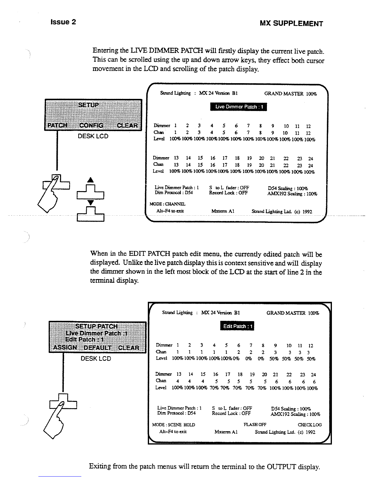
Entering
the
LIVE
DIMMER
PATCH
will
firstly
display
the
current
live
patch
.
This
can
be
scrolled
using
the
up
and
down
arrow
keys, they
effect
both
cursor
movement
in
the
LCD
and
scrolling
of
the
patch
display
.
SETUP
PATCE#°
te
DltntnerPort
;
EdIi
PaICIt
~
ASSIGN
`tiEEAt3LT Cil
v
.
a
DESK
LCD
Strand
Lighting
:
MX
24
Version
BI
GRAND
MASTER
100%
Live
Dimmer
Patch
:
I
S
to
L
fader
:OFF
D54
Scaling
:
10D9o
AMX192
Scaling
:
10090
Dim
Protocol
:
D54
Record
Lock
:
OFF
MODE
:CHANNEL
Alt-F4
to
exit
Mxtenn
A1
Strand
Lighting
lid
.
(c)
.
1992
. . .
. .
When
in
the
EDIT
PATCH
patch
edit
menu,
the
currently
edited
patch
will
be
displayed
.
Unlike
the
live
patch
display
this
is
context
sensitive
and
will
display
the
dimmer
shown
in
the
left
most
block
of
the
LCD
at
the
start
of
line
2
in
the
terminal display
.
Strand
Lighting
:
MX
24
Version
BI
GRAND
MASTER
l00%
Edit
Patch
:
t
Live
Dimmer
Patch
:
1
S
to
L
fader
:
OFF
D54
Scaling
:
I
OD%
AMX192
Scaling
:
100%
Dim
Protocol
:
D54
Record
Lock
:
OFF
MODE
:SCENE
HOLD
FLASHOFF
CHECKLOG
Alt-F4
to
exit
Mxtemr
At
Strand Lighting
Lid
.
(c)
1992
Exiting
from
the
patch
menus
will
return
the
termi
live
Dimmer
Patch
:
1
MX
SUPPLEMENT
to
the
OUTPUT
display
.
Dirrnner
1
2 3 4
5
6
Chat
1
2 3 4 5
6
7 8
9
10
7
8 9 10
11
11
12
12
Level
100%
100%
100%100%I00%100%100%IOD%100%
1009o
100%
30090
Dimmer
13 14 15
16
17 18 19
20
21
22 23 24
Chin
13 14
15 16
17 18 19
20
21
22 23 24
Level
100%100%
]0090IOD%100%
100%100%
IOD%100%
10090100%
100%
Dimmer
1
2 3 4 5 6 7
Chan
1
1 1 1
1
2 2 8
2
9
3
10
3
11
12
3 3
Level
100%
100%
l0D%
I00%IOD9o09o
0%
0%
50%50% 50%50%
Dimmer
13
14 15
16 17
18 19
20
21
22 23 24
Chan
4
4
4
5 5 5 5 5 6 6 6 6
Level
10D%
100%
10D%
70%
7090
70% 70%70%
100%
100%
10090100%

MX
SUPPLEMENT
Issue 2
Printing
In
order
to
use
the
printer,
the
terminal
must
be
disconnected and
the
printer
plugged
in
.
When
entering the
print
menu,
the
terminal
output
is
always
halted,
allowing
a
print
to
be
made
.
Terminal
output
will
resume
only
when
not
in
the
print
menu,
any
printing
has
completed
and
any
key
if
pressed
on
the
console
.

Issue
2
MX
SUPPLEMENT
MIDI
APPLICATIONS
Introduction
The
main
purpose
of
incorporating
MIDI
into
Strands
lighting
desks
is
to
create
an
interface
between
light
and
sound
.
MIDI
is
now
an
industry
standard,
in
much
the
same
way
that
SMPTE
is
for
the
film
industry,
and
all
faders
and
switches
on
MX
are
allocated
unique
MIDI
codes
for
use
with
this
interface
.
MIDI
transmits
and
receives
over 16
channels
.
These
are
dedicated
MDI
channels
and
have
nothing
in
common
with
any
light
channels
.
All
MIDI
devices
generally
default
to
Channel
1
including
MX
.
Each
MIDI-equipped
instrument
usually
contains
a
receiver,
a
transmitter,
and
an
optional
socket
providing
a
through
(THRU)
facility
for
relaying
information
to
other
Midi
devices
.
MX
contains
these three
ports
.
The
THRU
socket
is
a duplicate
of
the
signals
on
the
IN
socket
therefore
allowing
information
from
a
-master
unit to
be
relayed-to-another
MIDI
unit
. -
A
-
fine is
normally
drawn
signifying
this
as
shown
in
the figure
below
.
Transmit
Relay
Receive
1
Out
Thru
I
n
MostMidi
sequencers
are
software
orientated
and
run
on
a
variety
of
personal
computers,
the
most
popular being
the
Atari,
Mac
.
and
more
recently
the
P
C
.
At
present
only
the
Atari
has
built
in
Midi
Sockets,
hence
to
date
this
has
been
the
most
popular
computer
for
Midi
applications,
others require
separate
interfaces
to
be
purchased
before
Midi
software
can
be
utilised
.
MX
SUPPLEMENT
Issue
2
1
IN
.'
TRK
.2
BASS
'"
TRK
.3
PIANO
cccccmc~ca
1
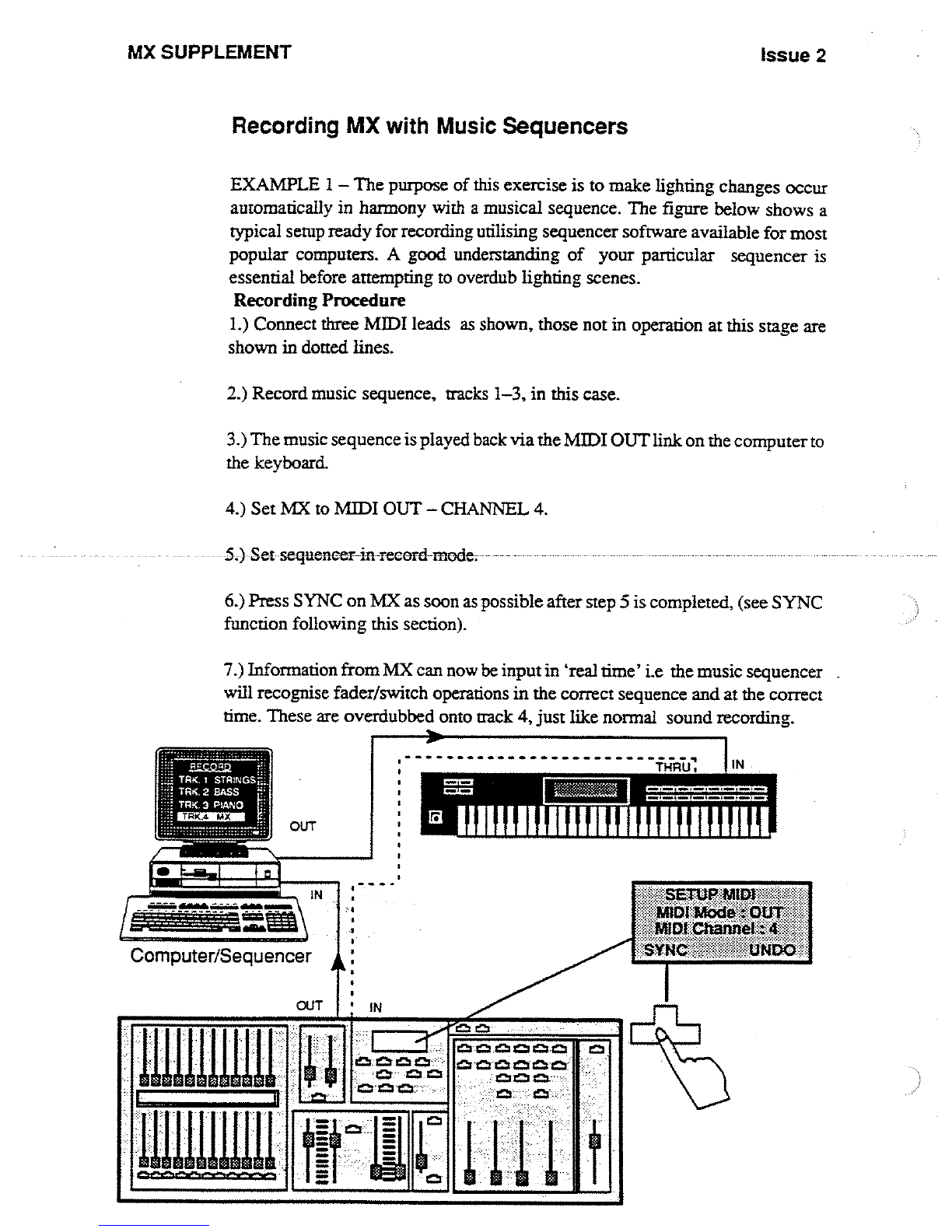
Recording
MX
with
Music
Sequencers
EXAMPLE
1-
The
purpose
of
this
exercise
is
to
make
lighting
changes
occur
automatically
in
harmony
with
a
musical
sequence
.
The
figure
below
shows
a
typical
setup
ready
for
recording
utilising
sequencer
software
available
for
most
popular
computers
.
A
good
understanding
of
your
particular
sequencer
is
essential
before
attempting
to
overdub
lighting
scenes
.
Recording Procedure
1 .)
Connect
three
MIDI
leads
as
shown,
those not
in
operation
at
this
stage
are
shown
in
dotted
lines
.
2
.)
Record
music
sequence,
tracks
1-3, in
this
case
.
3
.)
The
music sequence
is
played
back
via the
MIDI
OUT
link
on
the
computer
to
the
keyboard
.
4
.)
Set
MX
to
MIDI
OUT
-
CHANNEL
4
.
5
.)
Set-sequencer-in
record
mode
.
6
.)
Press
SYNC
on
MX
as
soon
as
possible
after
step
5
is
completed,
(see
SYNC
function
following
this
section)
.
7
.)
Information
from
MX
can
now
be
input
in
`real
time'
i
.e
the
music
sequencer
will
recognise
fader/switch
operations
in the
correct
sequence
and
at
the
correct
time
.
These
are
overdubbed
onto
track
4,
just
like
normal
sound
recording
.
30
cm
0,123
I=]z
I=
=cc,cca
o=a
.
Issue 2
MX
SUPPLEMENT
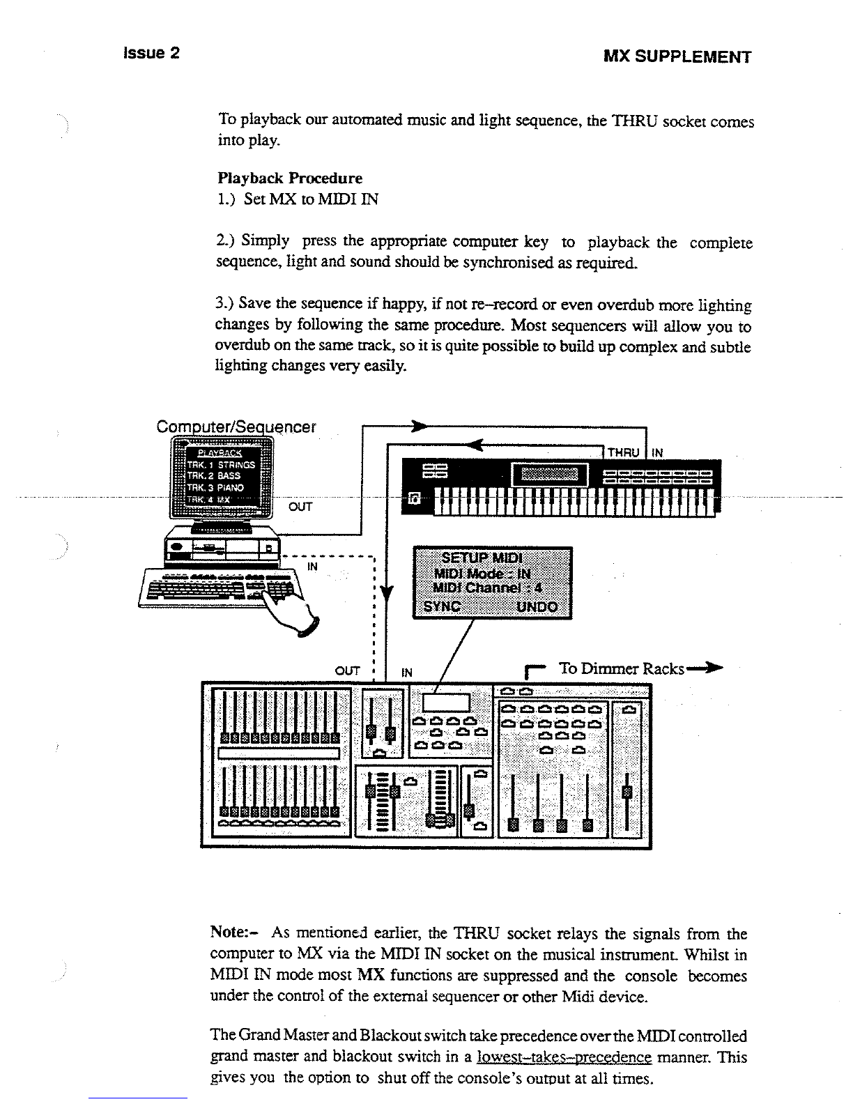
To
playback
our
automated
music
and
light
sequence,
the
THRU
socket
comes
into
play
.
Playback
Procedure
1
.)
Set
MX
to
MIDI
IN
2
.)
Simply
press
the appropriate
computer
key
to
playback
the
complete
sequence,
light
and
sound
should
be
synchronised
as
required
.
3
.)
Save
the
sequence
if
happy,
if
not
re-record
or
even
overdub
more
lighting
changes
by
following
the
same
procedure
.
Most
sequencers
will
allow
you
to
overdub
on
the
same
track,
so
it
is
quite
possible
to
build
up
complex
and
subtle
lighting
changes
very
easily
.
Computer/Sequencer
nuu~u
Note
:
As
mentioned
earlier,
the
THRU
socket
relays the
signals
from
the
computer
to
MX
via the
MIDI
IN
socket
on
the
musical
instrument
.
Whilst
in
MIDI
IN
mode
most
MX
functions
are
suppressed
and
the
console
becomes
under
the
control
of
the
external
sequencer
or
other
Midi
device
.
The
Grand
Master
and
Blackout
switch take
precedence
over
the
MIDI
controlled
grand
master
and
blackout
switch
in
a
lowest-takes-precedence
manner
.
This
gives
you
the
option
to
shut
off the
console's
output
at
all
times
.

MX
SUPPLEMENT
Issue
2
During
MIDI
IN
mode,
the
LCD
will
be
fixed
to
a
MIDI
IN mode
display
.
However,
the
MIDI
mode
may
be
changed
to
MIDI
OFF,
MIDI
OUT
or
MIDI
SLAVE
mode
.
Normal
console
operation
can
only
occur
in
MIDI
OFF
and
MIDI
OUT
modes
.
Note
:-
When
the
mode
is
changed
back
to
either
MIDI
OFF
or
MIDI
OUT
mode,
the
output
will
be
controlled
immediately
by
the fader
levels set
on
the
console
.
The
state
of
the console, as
set
by
MIDI
(such
as
effect
control
and
selection
of
operating
modes)
will
be
maintained
when
MIDI
modes
are
switched
.
SYNC
Function
SYNC
records
a
`snapshot
'
of
the
desk
i
.e
it
acts
as
a form
of
reset
signal
by
resetting
the
MX
parameters
shown
back
to
the
state
they
were
in just
before
the
button
is
pressed
.
A
good
illustration
of
this
is
when
used with
our musical
sequence
example
just
explained
.
tni
a~to
e
Parameters
transmitted
by
SYNC
S
cene Page
FX
Page
C
Master
Paae
Dimmer
Patch
No
Active
CID
master
Mode
Flash
Mode
Flash
State
Flash
Enable
Hold
State
Blackout
State
Selected
FX No
.
In
effect
this
means
that
when
MX
is
setup
for
other
applications
the
information
for the
previous
example
setup
is
not
lost
as
it
has
been
stored
with
the
music
sequence
software
.
When
the
example
is
used
again
and
the
sequencer
is
played
back,
the
first
bit
of
information
transmitted
to
MX
will
be
the
code
for resetting
MX
back
to
its
starting
position,
assuming
the
recording
procedure has
been
correctly
adhered
to
.
Issue
2
MX
SUPPLEMENT
Slave
Mode
In
this
mode,
it
now
becomes
possible
to
link-up
2
MXs
for
the
purposes
of
increasing
channel
capacity
.
The
maximum
channel
capacity
of
MX
is
48,
should
more
channels
be
desirable,
another
MX
can
be
linked
and
setup via
the
MIDI
ports
.
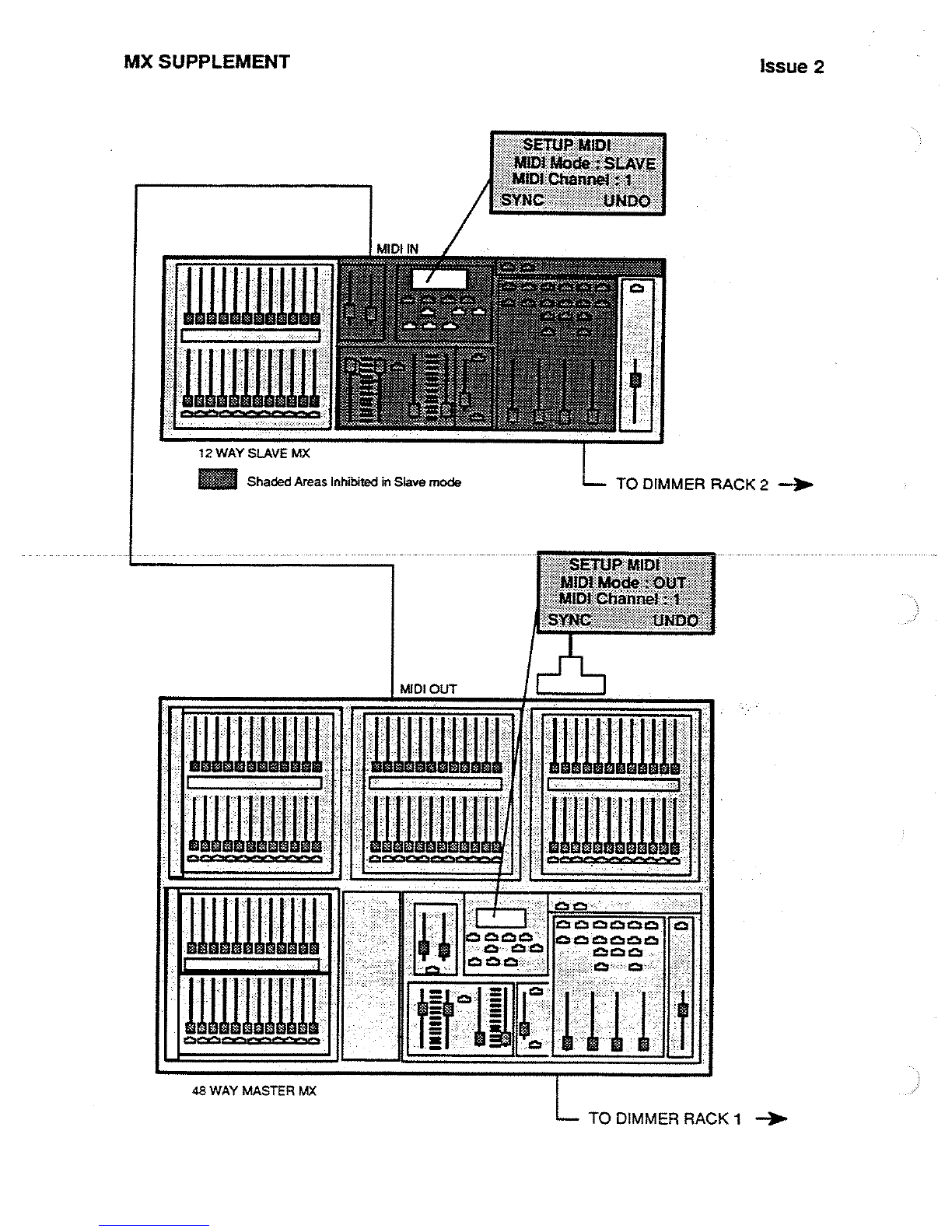
In
the
configuration
shown,
the
48
way
MX
becomes
the
master
unit
whilst
the
12
way
becomes
the
slave
.
All
controls
on
the
12
way
unit
are
inhibited
apart
from
the
Channel
faders,
Master
faders
and
Blackout
switch
.
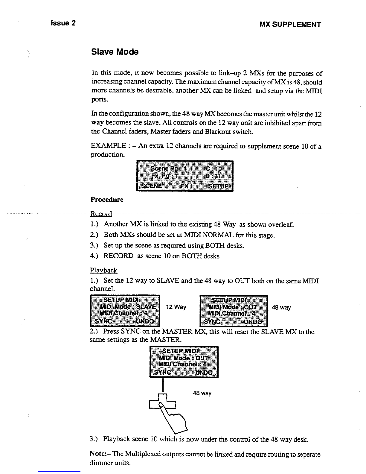
EXAMPLE
:
-
An
extra 12
channels
are
required
to
supplement
scene
10 of
a
production
.
Procedure
1
.)
Another
MX
is
linked
to
the
existing
48
Way
as
shown
overleaf
.
2
.)
Both
MXs
should be
set
at
MIDI
NORMAL
for
this
stage
.
3
.)
Set
up
the
scene
as
required
using
BOTH
desks
.
4
.)
RECORD
as
scene
10
on
BOTH
desks
Playba
ck_
1
.)
Set
the
12
way
to
SLAVE
and
the
48
way
to
OUT
both
on
the
same
MIDI
channel
.
2
.)
Press
SYNC
on
the
MASTER
MX,
this
will
reset
the
SLAVE
MX
to
the
same
settings
as
the
MASTER
.
3
.)
Playback
scene
10
which
is
now
under
the
control
of
the
48
way
desk
.
Note
:-The
Multiplexed
outputs
cannot be
linked
and
require routing
to
seperate
dimmer
units
.
MX
SUPPLEMENT
Issue 2
Qcmch=
uuuium
~uiuuuu
~W1WW
~u°uu~
uiuuu
Ullll
cm=cw=
-
-1
-
a8
WAY
MASTER
MX
SETi1P
MIDI
IMM&WkSLAVE
wtthlilrli~
{hl8rn~
~
12
WAY
SLAVE
MX
12
WW(
SUWE
W
x
=
Shaded
Areas
Inhibited
in
Slave
mode
L
TO
DIMMER
RACK
2
--)P-
P,
................ ..................
L
TO
DIMMER
RACK
1
--)N-
Issue
2
MX
SUPPLEMENT
SETI
tE3l
:
MOde
=
LChann
REMOTE
GO
CUE
It is
now
possible to
remotely
triggerlighting
scenes
that
have
been
pre-recorded
into
the
CD
sequencer
by
means
of
an
external
control
such
as
an
audio
signal,
MIDI
timing
signal
or a
MIDI
PROGRAMME
CHANGE
command
.
This
feature
will
be
extremely
useful
to
any
production
that
has
music
or
sound
effects,
whether
it
beon
tape
orplayed
`live'
by
one
of today's
modern
keyboards
.
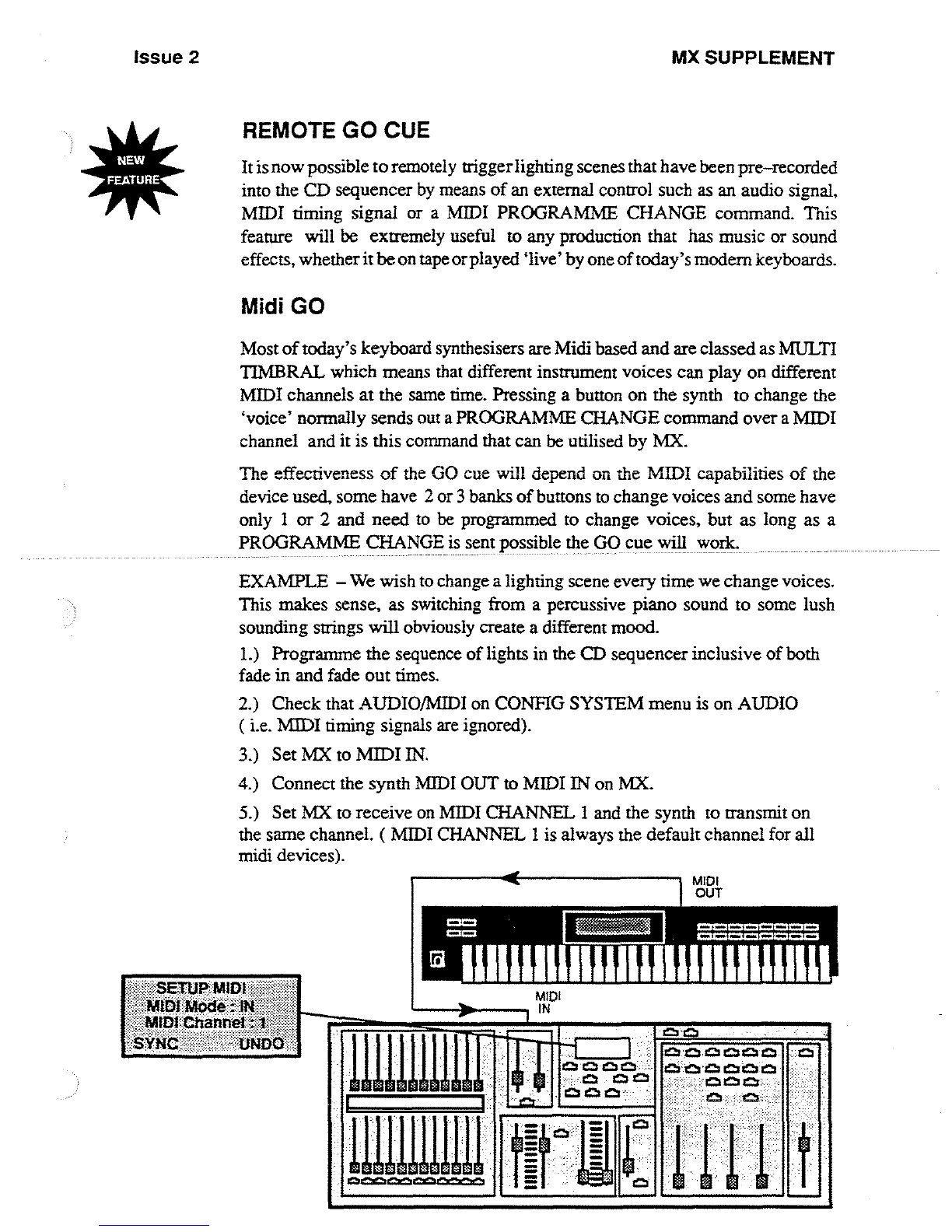
Midi
GO
Most
of
today's
keyboard
synthesisers
are
Midi
based
and
are
classed
as
MULTI
TIMBRAL
which means
that
different
instrument
voices
can
play
on
different
MIDI
channels
at
the
same
time
.
Pressing
a button
on
the synth to
change
the
,
voice'
normally
sends
out a
PROGRAMME
CHANGE
command
over
a
MIDI
channel
and
it
is
this
command
that
can
be
utilised
by
MX
.
The
effectiveness
of
the
GO
cue
will
depend
on
the
MIDI
capabilities
of
the
device
used,
some
have
2 or
3
banks
of
buttons
to
change
voices
and
some
have
only
I
or
2
and
need
to
be
programmed
to
change
voices,
but
as
long
as a
PROGRAMME
CHANGE
is
sent
possible
the
GO
cue
will
work
.
EXAMPLE
-
We
wish
to
change
a
lighting
scene
every
time
we
change
voices
.
This
makes
sense,
as
switching
from
a percussive
piano
sound
to
some
lush
sounding
strings
will
obviously
create
a
different
mood
.
1 .)
Programme
the
sequence
of
lights
in
the
CD
sequencer
inclusive
of
both
fade
in
and
fade
out
times
.
2
.)
Check
that
AUDIO/MIDI
on
CONFIG
SYSTEM
menu
is
on
AUDIO
(
i .e
.
MIDI
timing
signals
are
ignored)
.
3
.)
Set
MX
to
MIDI
IN
.
4
.)
Connect
the
synth
MIDI
OUT
to
MIDI
IN
on
MX
.
5
.)
Set
MX
to
receive
on
MIDI
CHANNEL
1
and
the
synth
to transmit
on
the
same
channel
. (
MIDI
CHANNEL
1 is
always
the
default
channel
for
all
midi
devices)
.
MIDI
IN
C3
n
C3 CZ
~
os
aQ

MX
SUPPLEMENT
"
A
musical
piece
can
now
be played
`live'
and
at
the
appropriate
time
the synth
voice button
can
be
pushed
and
as the
sound
changes
a
lighting
crossfade
will
occur
as
programmed
.
PIANO
I
CnR
.
PERU
ORGAN
GUITAR
BASS
Issue 2
Note
:-The
buttons are
not
scene
selective
i
.e
if
you
had 20
scenes
in
the
CD
sequencer, pressing
button
10 does
not
mean
the
sequence
will
jump
to
scene
10
.
ANY
button
pressed
will
make
MX
go
to
the
next
scene
in
sequence
.
Audio
/
MIDI
Fader
The
primary
function
of
the
Audio
/Iv11DI
fader
is
to
act
as
a
threshold
level
for
triggering
audio
signals
which
may
be used
to
control
remote
GO
cues
(see
next
Section)
.
If
the
AUDIO/MIDI
parameter
in
the
SYSTEM
SETUP
menu
is
set
to
MIDI
however,
then
it
is
possible
to
control
cues
by
means
of
clock cycles
i .e
in
reality
these
can
be regarded
as
actual
beats
of
music
.
Issue
2
MX
SUPPLEMENT
AUDIO
5
-PIN
DIN
IN
2 SignWGround
3
Left
Chance
4
Na
Connect
.
5
RipM
Chanrrol
Audio
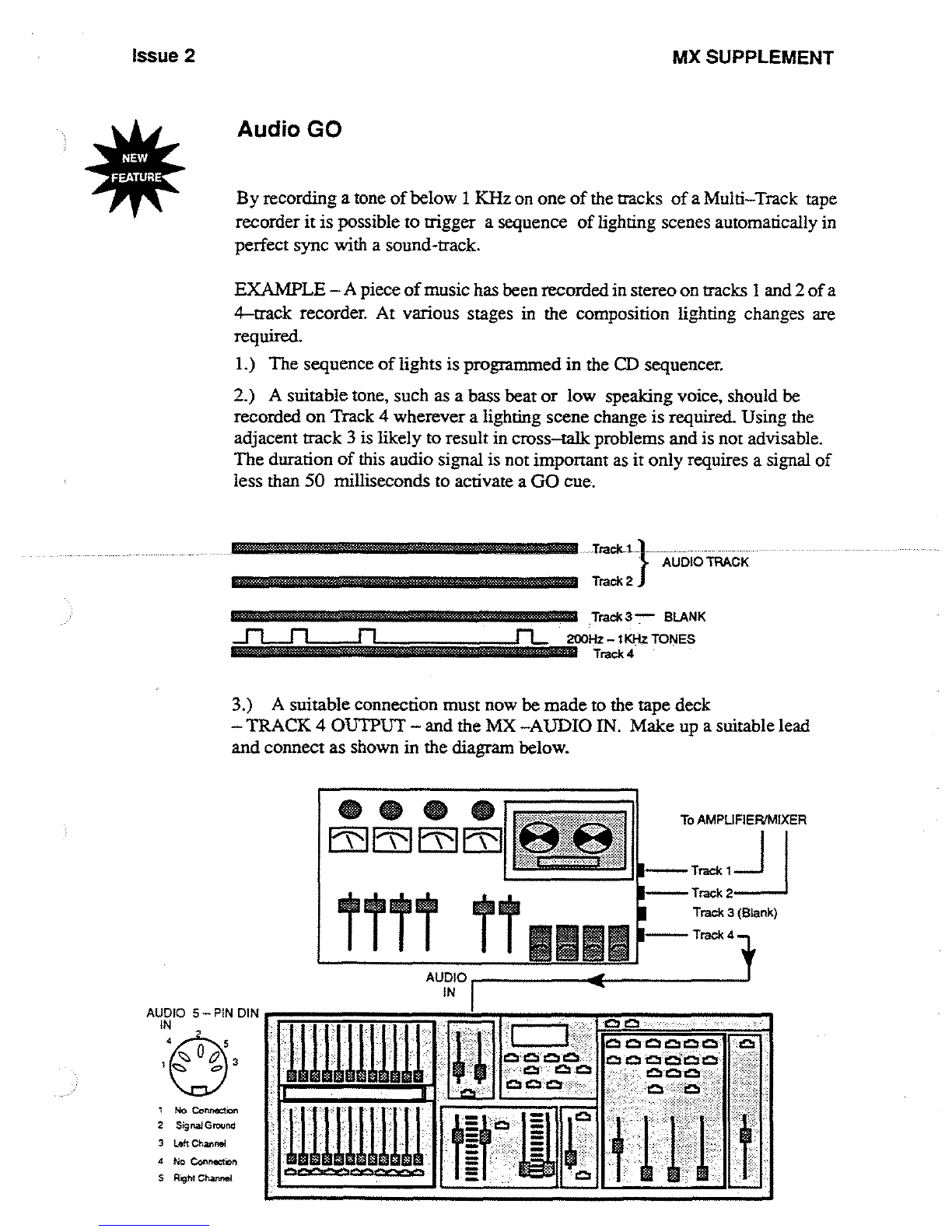
GO
By
recording
a
tone
of
below
1
KHz
on
one
of
the
tracks
of
a
Multi-Track
tape
recorder
it
is
possible to
trigger
a
sequence
of
lighting
scenes
automatically
in
perfect
sync
with
a
sound-track
.
EXAMPLE
-A
piece
of
music
has
been
recorded
in
stereo
on
tracks
1
and
2
of
a
4-track
recorder
.
At
various
stages
in
the
composition
lighting
changes
are
required
.
1
.)
The
sequence
of
lights
is
programmed
in
the
CD
sequencer
.
2
.)
A
suitable
tone,
such
as
a
bass beat or
low
speaking
voice,
should
be
recorded
on
Track
4
wherever
a
lighting
scene
change
is
required
Using
the
adjacent
track
3
is
likely
to
result
in
cross-talk
problems
and
is
not
advisable
.
The
duration
of
this
audio
signal
is
not
important
as
it
only
requires
a
signal
of
less
than
50
milliseconds
to
activate
a
GO
cue
.
Trick
I
}
AUDIO
TRACK
3
.)
A
suitable
connection
must
now
be
made
to
the
tape
deck
-TRACK
4
OUTPUT
- and
the
MX
AUDIO
IN
.
Make
up
a
suitable
lead
and
connect
as
shown
in
the
diagram
below
.
ttrr
TT
AUDIO
I
IN
Track
2
Track 3
"
BLANK
200Hz-SKHz
TONES
i
Track 4
E
To
AMPLIFIERIMIXER
I-
Track
I
I
I-
Track
2
--
Track
3
(Blank)
Track 4 -,
Ch
&ZCM
66
4b
MX
SUPPLEMENT
Issue 2
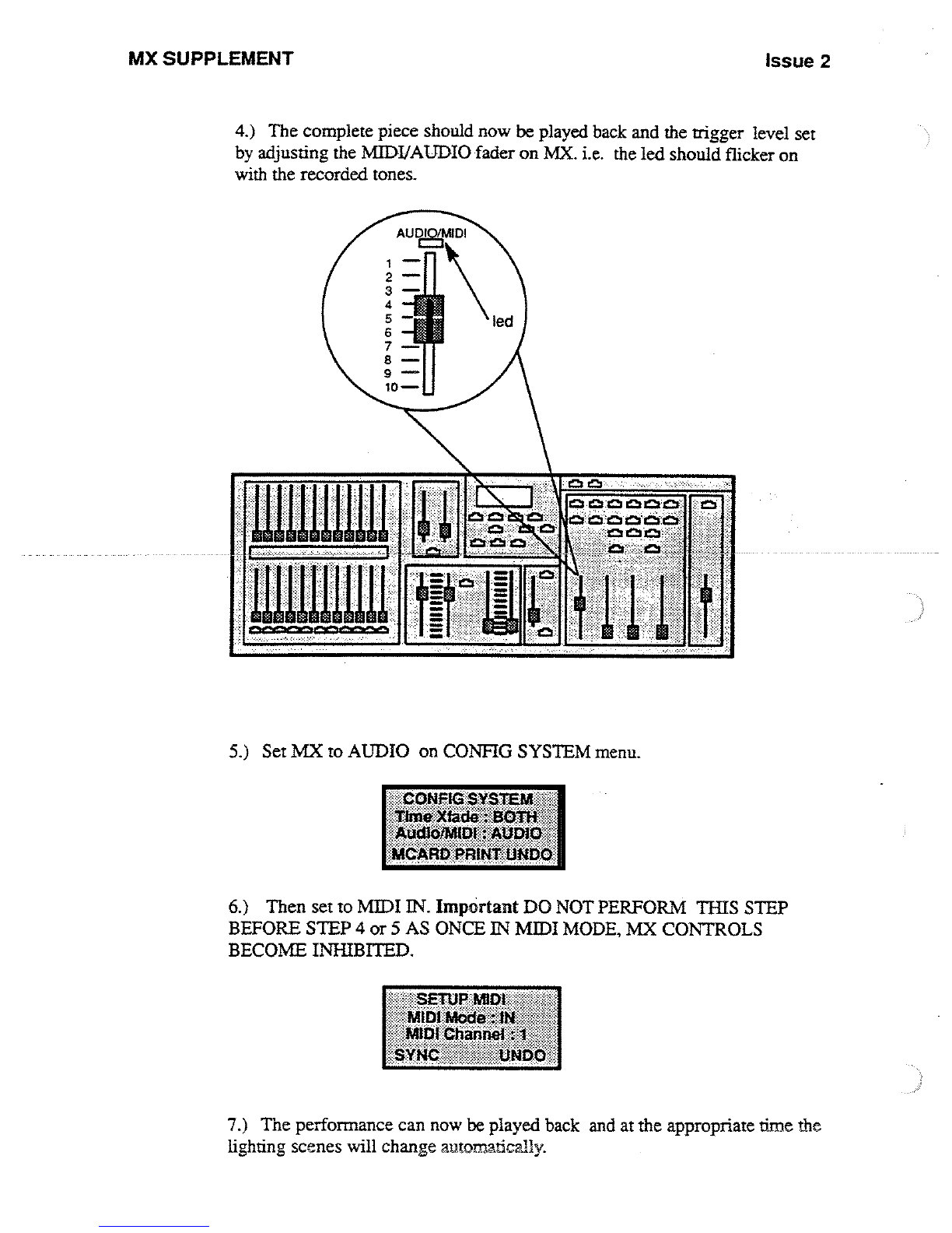
1)
The
complete
piece
should
now
be
played
back
and
the
trigger
level
set
by
adjusting
the
MIDI/AUDIO
fader
on
MX
.
i
.e
.
the
led
should
flicker
on
with
the
recorded
tones
.
~uswuiu~
r=11
'~
<CONFP
TttneXfada
9_
:
.
.
it)
Set
143C
to
AUDIO
on
CONFIG
SYSTEM
menu
.
Q
Then
go
to
MIDI
IN
.
Important
DO
NOT
PERFORM
THIS
STEP
BEFORE
STEP
4
or
5
AS
ONCE
IN
MIDI
MODE,
MX
CONTROLS
BECOME
INHIBITED
.
7
.)
The
performance
can
now
be played
back
and
at
the
appropriate
time
the
lighting
scenes
will
change
automatically
.
Other manuals for MX
1
Table of contents
Other Strand Lighting Lighting Equipment manuals

Strand Lighting
Strand Lighting ClassicPalette User manual

Strand Lighting
Strand Lighting CD80 User manual

Strand Lighting
Strand Lighting MX User manual

Strand Lighting
Strand Lighting 100 User manual

Strand Lighting
Strand Lighting Contact Power Pack Original operating instructions

Strand Lighting
Strand Lighting Circular Saw User manual

Strand Lighting
Strand Lighting Wallrack User manual

Strand Lighting
Strand Lighting EC21 User manual


