Streamax AD Plus User manual
AD Plus
Installation Guide

www.streamax.com
Page 2of 52
Type of document
General
Product planning document
Internal use only
Version
52 pages in total
V1.6
Revision History
Date
Revision
Modification Description
Author
April 16, 2021
V 1.0
First draft of AD Plus solution
May 10, 2021
V 1.1
Modification of format and content
June 17,2021
V 1.2
Modification of the device image
September 23, 2021
V1.3
Supplementary precautions for
inertial navigation installation
Supplementary precautions for the
installation of glass-mounted and
countertop-mounted CA29M
October 27, 2021
V1.4
Modification of ADAS calibration
and DMS installation precautions
December 24, 2021
V1.5
Added BSD calibration
April 1, 2022
V1.6
Modification of ADAS/DSC/DMS
calibration
Zhouhao/Wangxiaoyong

www.streamax.com
Page 3of 52
Table of Contents
Foreword........................................................................................................................................................5
Important Instructions .................................................................................................................................5
1. System Overview..................................................................................................................................7
1.1 Product Overview..............................................................................................................................7
1.2 Schematic Diagram of System Connection-Power Supply through OBD.........................................7
1.3 Schematic Diagram of System Connection-Power Supply through Discrete Wire...........................7
2. Preparation for Installation.................................................................................................................8
2.1 Technical Requirements for Installation............................................................................................8
2.2 Understanding of Installation Environment.......................................................................................8
2.3 Confirmation of Vehicle Conditions and Vehicle-related Electrical Information.............................8
2.4 Power Supply Connection of Vehicle................................................................................................8
2.5 Connection of Necessary Signal Cables............................................................................................9
3. Preparation of List of Installation Materials and Tools...................................................................9
3.1 Inspection as per Packing List...........................................................................................................9
3.2 Preparation of Installation Tools .....................................................................................................10
3.3 Preparation of SIM Card and Micro SD Memory Card...................................................................12
4. Installation of AD Plus.......................................................................................................................12
4.1 Installation of SIM Card and Memory Card....................................................................................12
4.2 Selection of DVR Installation Area.................................................................................................13
4.3 Installation of DVR Bracket............................................................................................................14
4.4 Installation of DVR .........................................................................................................................16
4.5 Adjustment and Fixation of DVR....................................................................................................17
4.6 Power Supply Connection, Connection of Signal Cables and Wiring.............................................18
4.6.1 Power Supply Connection ......................................................................................................18
4.6.3 Wiring.....................................................................................................................................22
5. Calibration of AD Plus.......................................................................................................................23
5.1 ADAS Calibration ...........................................................................................................................23
5.1.1 Connection with APP..............................................................................................................23
5.1.2 Installation Parameters Measurement of the ADAS Camera Lens ........................................24
5.1.3 Calibration of ADAS Camera Lens........................................................................................25
5.2 DSC Calibration ..............................................................................................................................29
5.2.1 Left and Right Rudder Setting ................................................................................................29
5.2.2 Cab Camera Angle Adjustment ..............................................................................................30
5.3 BSD Installation and Calibration......................................................Error! Bookmark not defined.
5.3.1 Top-view Installation and Calibration ......................................Error! Bookmark not defined.
5.3.2 Side-mounted Calibration..........................................................Error! Bookmark not defined.
5.3.3 Blind Spot in Front of the Vehicle .............................................Error! Bookmark not defined.
6. Installation and Calibration of Optional Components...................................................................31
6.1 DMS Camera...................................................................................................................................31

www.streamax.com
Page 4of 52
6.1.1 Requirements for Installation Position...................................................................................32
6.1.2 Requirements for Installation Angle.......................................................................................33
6.1.3 Requirements for Installation Details.....................................................................................34
6.1.4 Installation Steps....................................................................................................................34
6.1.5 Calibration Requirements.......................................................................................................39
6.2 BSD Installation and Calibration.....................................................................................................42
6.2.1 Top View Camera Installation and Calibration.....................................................................42
6.2.2 Calibration for lateral side installation..................................................................................46
6.2.3 Calibration of Blind Spot in Front Top View .........................................................................50
6.2.4 Principle of Actual Vehicle Routing.......................................................................................51
7. Acceptance and Cleaning...................................................................................................................51
7.1 Cleaning...........................................................................................................................................51
7.2 Installation Acceptance....................................................................................................................52

www.streamax.com
Page 5of 52
Foreword
This AD Plus Installation Guide is hereby prepared to better guide engineering personnel to
install AD Plus and its accessories properly and quickly, and to improve installation
efficiency.
This document mainly includes the following parts: foreword, system overview, preparation
for installation, introduction to installation, and acceptance and cleaning.
This document is applicable to installation engineering personnel.
Streamax Technology Co., Ltd. has the right of final interpretation for this document, and
reserves the right to make corrections to this document or to make changes to the information
and description herein. No prior notice will be given if there is any change.
Important Instructions
1. Before installation, please park the vehicle on the horizontal ground and shut down the
engine (do not park the vehicle on a ramp or an inclined road).
2. Please read the section of packing list carefully and check carefully at the time of
unpacking.
3. Please read the section of tool list carefully and provide installation tools before product
installation.
4. Before installation, please observe the vehicle environment and follow the principles
below:
a. The installation position and wiring of the product shall neither affect the driver's
view nor affect the adjustment of the rearview mirror and sun visor;
b. The camera lens for monitoring the road condition ahead of the vehicle must be
within the working range of the windshield wiper;
c. The installation position of the camera for monitoring the driver in the vehicle shall
comply with local regulations;
d. The installation position shall be convenient for the replacement and maintenance of
Micro SD card and SIM card.
5. The appropriate installation position shall be selected according to the vehicle
environment, and this document is for reference only.
6. The appropriate power supply connection method shall be selected according to the
vehicle environment. If discrete wire connectors are adopted, connection to the
power supply and all signal cables of vehicle is required, and shall be carried out by
specialized personnel, as it may be dangerous for non-specialized personnel to
operate the power system of the vehicle without authorization. This document is for
reference only.
7. In case of any problem in the installation for special vehicles, please contact the product
supplier in time for support.
8. Veyes App is required to debug and configure AD Plus during installation.
9. Please scan the QR code below, or search and download the Veyes APP in the App Store.
After the download is completed, connect the APP to AD Plus for related operations
according to the prompt on the interface of the APP.

www.streamax.com
Page 6of 52
IOS (Apple Store)
Foreign Android (Google Store)
www.streamax.com
Page 7of 52
1. System Overview
1.1 Product Overview
AD Plus is a dual-camera integrated intelligent Digital Video Recorder (DVR)
designed for driving monitoring and safety risk control, with advantages of simple
installation, comprehensive functions and low price.
The deep learning technology is adopted for the intelligent algorithm of AD Plus.
AD Plus has the features of advanced driver-assistance system (ADAS) and
intelligent cockpit, and can effectively identify the hazards such as front collision,
close car-following and lane departure, as well as intelligently identify unsafe
driving behaviors of driver such as use of mobile phone and seat belt unfastened
during driving. With DMS camera or BSD camera, the product can further
implement the function of driver status monitoring or blind spot pedestrian
detection. With intelligent auxiliary functions, the product can identify potential
risks in real time and remind drivers to avoid them in time in case of any driving
safety risks, thus effectively reducing accident risks.
The product is suitable for most weather conditions such as day and night, rain and
snow, and can be installed on buses, taxis, ordinary passenger cars, passenger
vehicles, freight vehicles, dangerous goods transport vehicles, school buses, muck
trucks, sanitation vehicles and other vehicles.
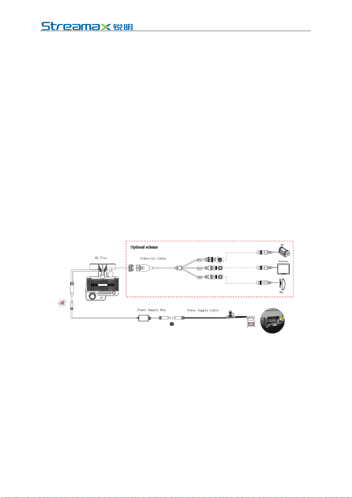
1.2 Schematic Diagram of System Connection-Power Supply through
OBD
1.3 Schematic Diagram of System Connection-Power Supply through
Discrete Wire

www.streamax.com
Page 8of 52
2. Preparation for Installation
2.1 Technical Requirements for Installation
Relevant personnel shall be familiar with the functions, applications and the overall
composition principle of the product.
Relevant personnel shall understand the electrical circuits and structure of motor
vehicles, and common installation methods of in-vehicle equipment.
2.2 Understanding of Installation Environment
Before equipment installation, relevant personnel shall have a clear understanding
of the vehicle model concerned, the installation positions of the main unit and
auxiliary cameras of the DVR, the type and length of cables required for each
vehicle model, and the list of common auxiliary materials, so as to ensure successful
completion of equipment installation and commissioning.
2.3 Confirmation of Vehicle Conditions and Vehicle-related Electrical
Information
Confirmation of vehicle information is the basic precondition of successful
installation and also the guarantee of division of responsibilities to avoid any
damage to the vehicle. For each component, proceeding to next step is only allowed
after clear confirmation, and each operation shall be confirmed by the person in
charge of the vehicle and the installation personnel.
(1) Check the appearance and interior trims of the vehicle for any damage.
(2) Check whether the vehicle can ignite normally.
(3) Check whether the vehicle power supply system is in good condition.
*Note: Confirmation of the above information is crucial. Installation can only be
carried out after the above information is considered normal through confirmation.
2.4 Power Supply Connection of Vehicle
AD Plus has two power supply connection modes:
1. Quick plug-in type power supply connection through OBD interface: This
mode is suitable for quick installation by users themselves. For details of this
power supply mode, please refer to the accompanying AD Plus Product
Manual in the AD Plus packing box. It will not be detailed here.
2. Power supply connection through discrete wire: This mode requires operation
by specialized installation personnel. The following mainly describes the mode

www.streamax.com
Page 9of 52
of connection to the vehicle power supply according to the power cable
requirements of the product.
(1) Required tool: multimeter.
(2) Selection of power supply connection position
When the vehicle is shut down, use a test pencil to detect whether the circuit is live.
If it is live, it is judged as a constant power supply, and then measure the voltage.
When the vehicle is shut down and is in ACC position or ignition state, use a test
pencil to detect whether the circuit is live. If it is electrically neutral in shutdown
state, and is live in ACC position or ignition state, it is judged as an ACC power
cable, and then measure the voltage.
(3) Voltage measurement of power supply connection
Constant power supply: When the vehicle is shut down, use a multimeter to
measure whether the voltage of the constant power supply cable is about 24V. If the
voltage of multiple cables is about 24V in shutdown state, select the cable with
higher current as the constant power supply connection cable.
ACC:When the vehicle is in ACC position or ignition state, use a multimeter to
measure whether the voltage is about 24V. If the voltage is 0 in shutdown state and
about 24V in ACC position or ignition state, select the cable as the ACC power
supply connection cable.
*Note: During power supply connection, first conduct measurement at the positive
and negative terminals of the power supply with a multimeter, to avoid wrong
connection.
2.5 Connection of Necessary Signal Cables
Where required, the following signal cables must also be connected to enable the
intelligent assisted driving functions of AD Plus:
(1) Vehicle speed pulse cable or CAN data cable - to obtain accurate vehicle speed
data;
(2) Left and right steering signal cables - to obtain left and right steering
information of vehicle;
(3) Brake signal cable - to obtain vehicle braking information.
Please consult the maintenance engineer of the vehicle discipline for specific
position of vehicle speed pulse cable/CAN data cable. Generally, the left and right
steering signal cables and the brake signal cable are arranged on the fuse board
below the steering wheel or below the front passenger dashboard, and measurement
for these cables can be conducted using a multimeter.
*Note: If the measured signal is a pulse signal, the source of left steering/right
steering/brake signal shall be set as pulse on the setting interface of the main unit; if
the measured signal is a continuous high or low level signal, the source of left
steering/right steering/brake signal shall be set as level on the setting interface of the
main unit.
3. Preparation of List of Installation Materials and Tools
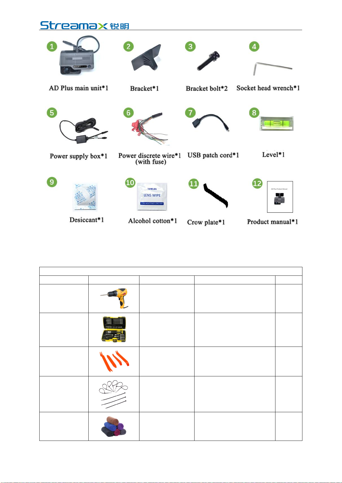
3.1 Inspection as per Packing List
After unpacking the product, please confirm whether the DVR is intact and whether
the accessories are complete.
www.streamax.com
Page 10 of 52
3.2 Preparation of Installation Tools
Before installation, the following installation accessories and tools shall be made
available.
List of Installation Tools and Accessories
S/N
Picture
Name of Tool
Purpose
Qty.
1
Torsion drill
Tighten screws
1 pcs
2
Common
screwdriver socket
Tighten screws; optional
1 pcs
3
Crow plate
Pry up the vehicle panel
1 pcs
4
Ties
Bundle cables
Several
5
Dry cleaning cloth
Clean the countertop
1 pcs
www.streamax.com
Page 11 of 52
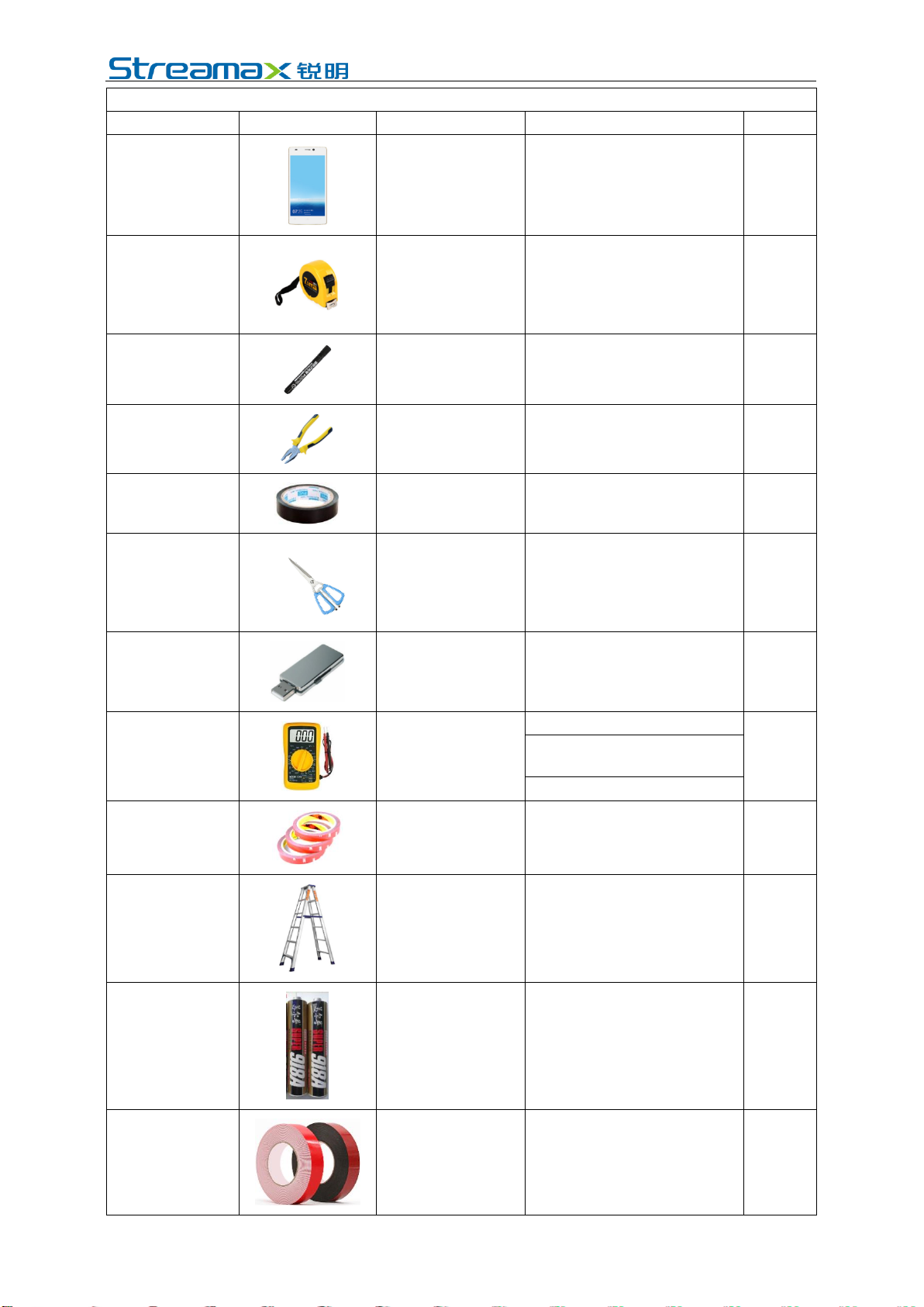
List of Installation Tools and Accessories
S/N
Picture
Name of Tool
Purpose
Qty.
6
Smartphone/pad
Install the EasyCheck App for
video preview and parameter
configuration
1 pcs
7
Steel tape
Measure the installation
height of the forward-facing
ADAS camera lens and assist
the installation in other
scenarios
1 pcs
8
Mark pen
Mark lines for main unit
installation
1 pcs
9
Cutting nippers
Cut and strip wires
1 pcs
10
Insulated rubber tape
Wrap wire ends
1 pcs
11
Scissors
Cut insulated rubber tape or
wire clip
1 pcs
12
USB flash disk
Standby
1 pcs
13
Multimeter
Locate vehicle power supply
1 pcs
Measure the conduction of
harness
Measure pulse signal
14
3M adhesive tape
Fix DMS camera
1 pcs
15
Three-legged ladder
Easy to install the BSD
camera
1pcs
16
Waterproof sealant
Waterproofing the backfill after
punching
1pcs
17
Waterproof tape
Waterproof protection for
outdoor wire connectors
1pcs
www.streamax.com
Page 12 of 52
The following installation tools are also required for the installation of DMS camera if
required:
DMS Camera Installation Tools
S/N
Picture
Name of Tool
Purpose
Qty.
1
PH2 cross screwdriver
1.Adjust and fix the DMS camera
lens at certain angle
(generally included in the DMS
camera packaging)
2. Tighten the lens screws; for ADAS
calibration
1pcs
2
3.5mm*25mm self-
tapping screw
Fix camera; standard
(generally included in the DMS
camera packaging)
4pcs
3.3 Preparation of SIM Card and Micro SD Memory Card
To ensure normal online communication and data storage of the equipment, please
prepare a supporting Micro SIM card and a Micro SD memory card that meets the
quality requirements before installation.
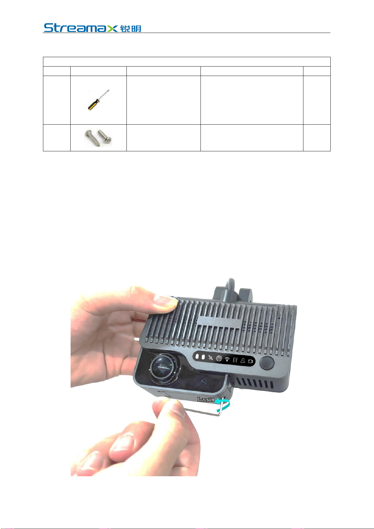
4. Installation of AD Plus
4.1 Installation of SIM Card and Memory Card
Take out the main unit (without powering on), and turn the card slot panel at the
bottom of the main unit counterclockwise with the L-shaped socket head wrench in
the package to open the panel.
Install SIM card and Micro SD card as shown in the figure below (pay attention to

www.streamax.com
Page 13 of 52
the insertion direction of the cards).
If you feel smooth and flexible during installation, and hear a clear sound of "Da"
when pushing in the cards completely, it indicates that the cards are installed in the
correct direction; if there is obvious friction resistance during installation, it
indicates that the installation direction is wrong. Take out the cards in time to avoid
any damage to the cards and the card holder.
*Note:
(1) Do not touch the surface of the metal contact of the SIM card with hands when
taking and installing the card, for fear of contaminating the SIM card by dust
and sweat stain.
(2) Before installing SIM card, please check the surface of the metal contact of the
SIM card for any dirt (such as dust, fingerprints and water stains). If any, clean
the surface with a piece of non-woven fabric or rubber.
(3) In Micro SD card slot 1, Micro SD card shall be pushed in with the metal strip
side down; in Micro SD card slot 2, Micro SD card shall be pushed in with the
metal strip side up.
After installation of SIM card and Micro SD card, fasten the card slot panel.
4.2 Selection of DVR Installation Area
Requirements for installation area of AD Plus:
(1) The DVR must be installed in the middle of the front windshield. It is
generally installed in the rearview mirror area above the centerline of the front
windshield. A deviation less than 5 cm on the left and right sides is allowed for
the installation position if it is not feasible to install the device in the middle as
required (The deviation of the DVR relative to the centerline of the front
windshield shall be calculated with the centerline of the front camera lens).
(2) When conditions permit, the height of the DSC camera lens shall not exceed
the height of the driver's eyes, and the installation position shall be as low as
possible provided that the driver's view is not obstructed. The linear distance
from the position of the DSC camera lens to the driver's face shall not be more
than 116cm.
(3) The external camera lens of the DVR must be within the working range of the
left and right wipers (to ensure that the external camera lens screen is clean and
free from stains)
(4) The preferred vertical distance from the external camera lens of the DVR to the
ground is in the range of 130cm-240cm
(5) Avoid installing other electronic devices around the DVR as far as possible,
including ETC, intelligent rearview mirrors, electronic tags; otherwise, they

www.streamax.com
Page 14 of 52
may affect the positioning signal of the device.
The installation position shall be determined in such a way that the DVR will not
hinder the driver from viewing the front blind spot reflector, and there is no
obstruction (such as interior rearview mirror or glass coating) within the field of
view in front of and around the internal and external cameras lens.
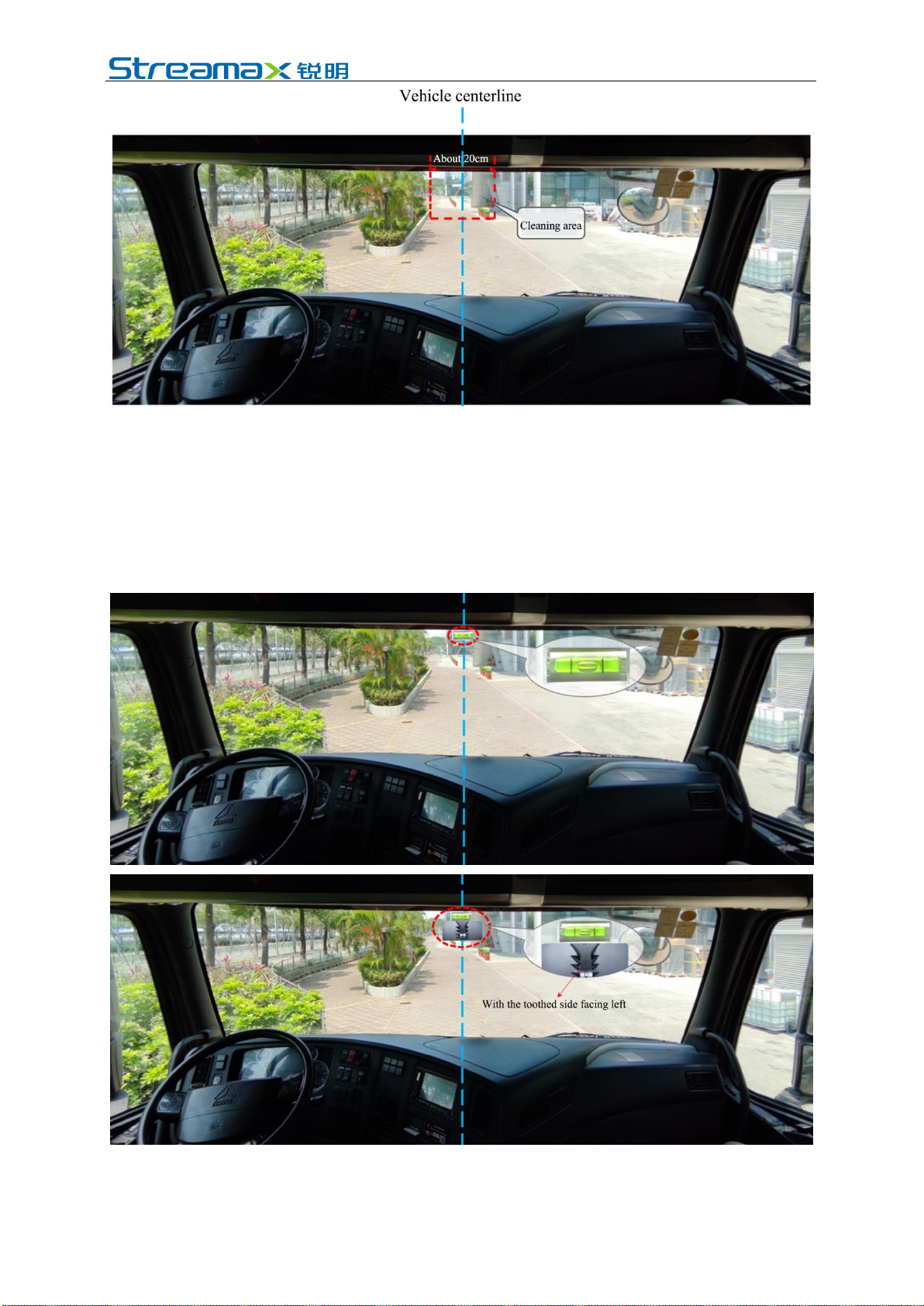
The installation area is generally selected as shown in the figure below:
4.3 Installation of DVR Bracket
Clean the interior and exterior of the glass in the target installation area with alcohol
cotton to ensure that no dirt on the glass in this area will affect the angle of view of
the external camera lens, and ensure the glass is dry.
www.streamax.com
Page 15 of 52
Park the vehicle on the horizontal ground, and then stick the level horizontally
above the target area (adjust the inclination angle of the level to center the bubble).
Stick the bracket with the connection of the bracket facing down (with the toothed
side facing left).
Tear off the 3M adhesive film on the bracket to stick the bracket horizontally on the
front windshield with the level as reference, and then press the bracket for 10s to
ensure no bubbles between the bracket and the glass.

www.streamax.com
Page 16 of 52
4.4 Installation of DVR
After fixing the bracket horizontally, remove the level, align it and stick on the right
side of the main unit in the area as shown in the figure below:
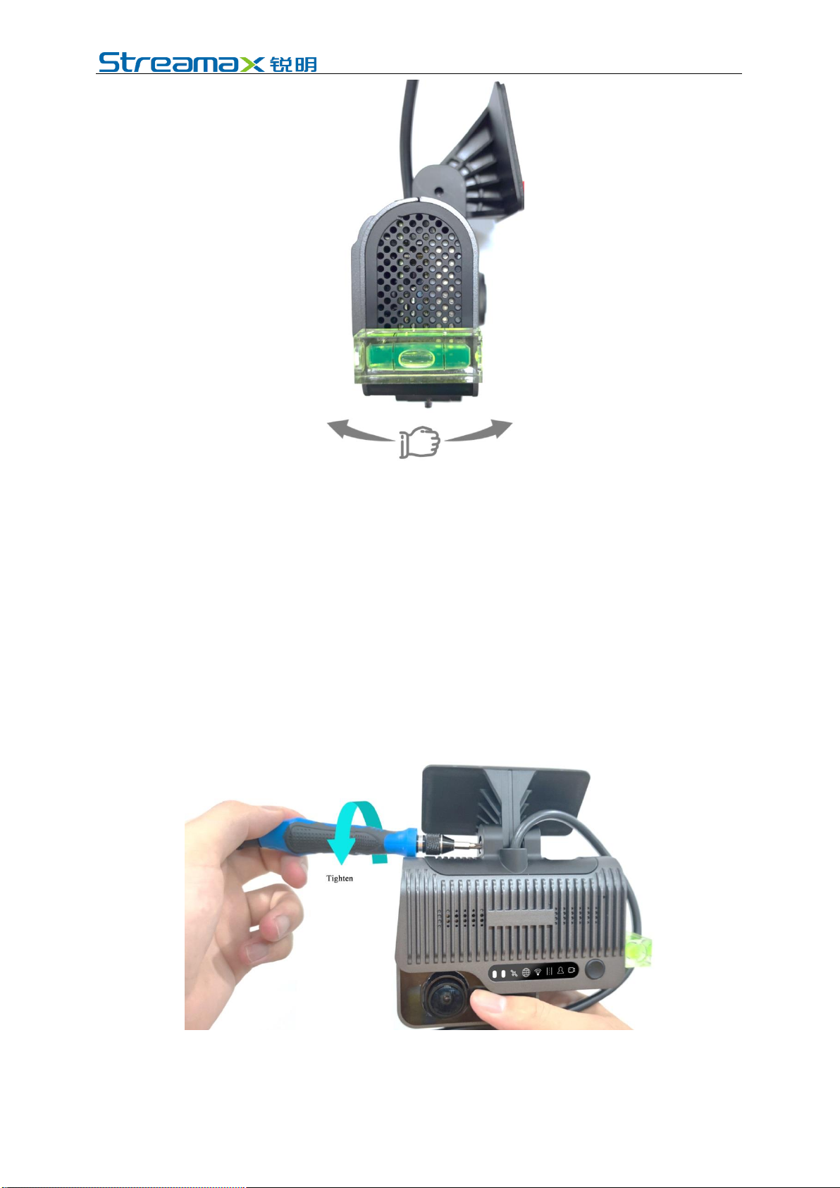
Connect the DVR to the bracket with the front side facing inward (with the teeth on
the left side of the bracket engaged with those on the left inner side of the DVR),
and tighten the bracket stud clockwise with a PH2 cross screwdriver (before
tightening, first adjust the DVR to be vertical).

www.streamax.com
Page 17 of 52
4.5 Adjustment and Fixation of DVR
Adjust the DVR back and forth to center the bubble in the level (indicating that the
DVR is vertical at this moment).
www.streamax.com
Page 18 of 52
Fasten the bracket stud to ensure that the angle of the DVR will not be changed
easily. Remove the level, and fix the DVR.
* Notes:
Make sure that the connection between the bracket and the main unit is fastened
(the device is rigidly connected with the vehicle), so that the main unit will not
shake easily. Otherwise, the GPS positioning will be inaccurate.
Only after the main unit is firmly connected with the vehicle can the device be
powered on.
If the device is fixed and installed after power-on, it shall be powered on again
before being tested or used.
The GPS module built in ADPlus is an inertial navigation module, and the above
requirements can ensure the normal operation of inertial navigation products.
4.6 Power Supply Connection, Connection of Signal Cables and Wiring
4.6.1 Power Supply Connection
www.streamax.com
Page 19 of 52
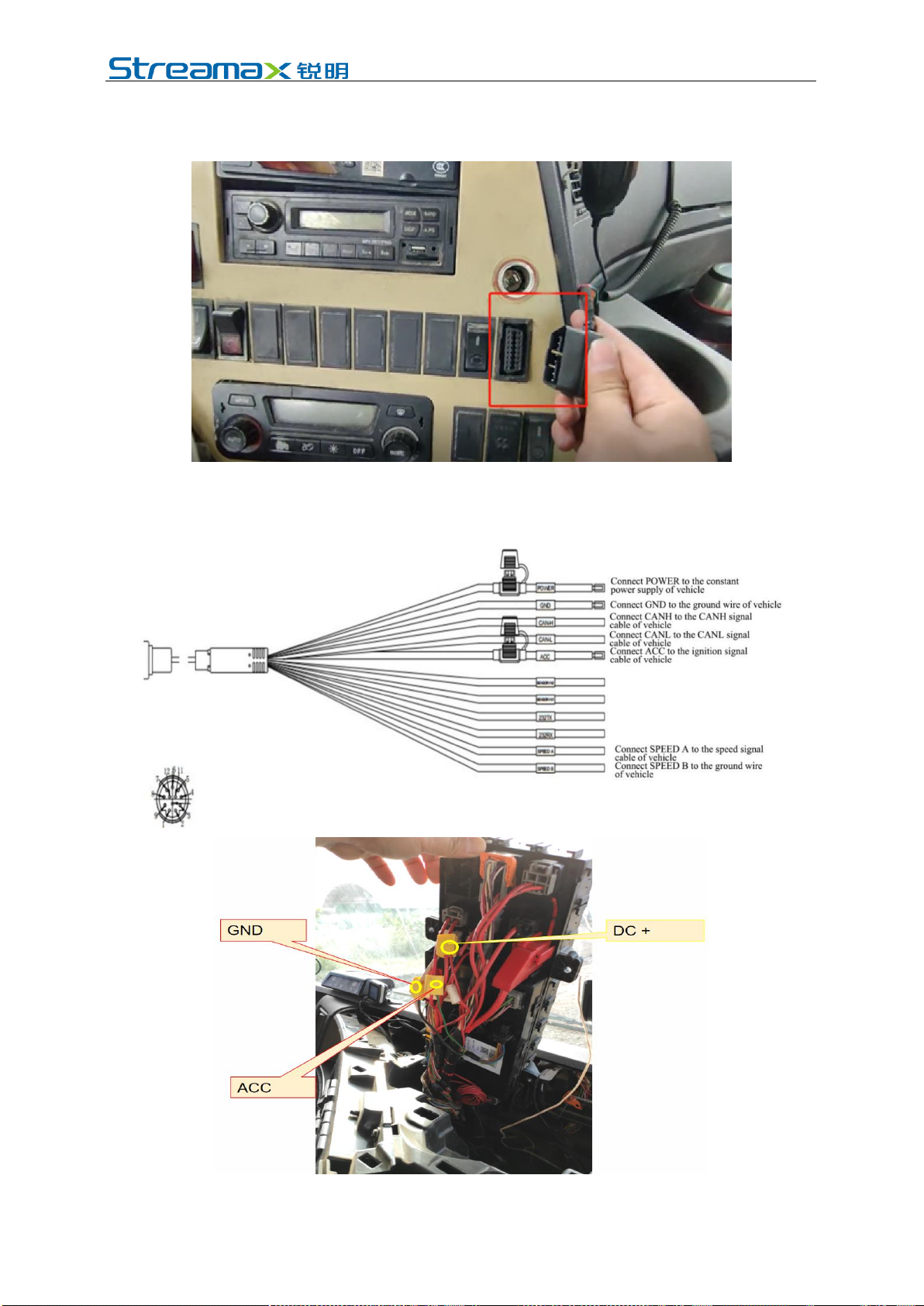
(1) If the mode of quick power supply connection through OBD interface is
adopted, locate the OBD interface of the vehicle and directly connect with the
interface.
(2) If the mode of power supply connection through discrete wire is adopted,
according to the definition of power discrete wire, connect
POWER/ACC/GND with the power cable of the vehicle, respectively.
www.streamax.com
Page 20 of 52
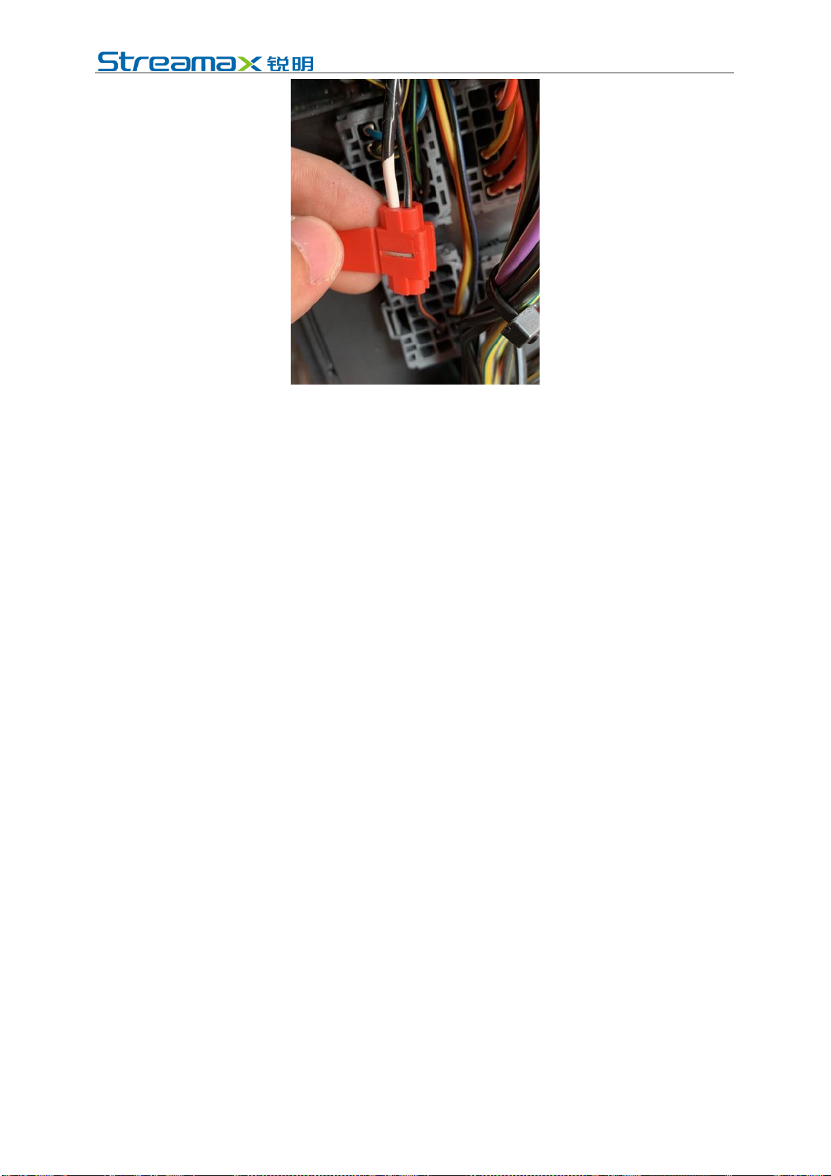
*Note:
The power cable shall be connected using "special stripping-free connection
terminal" where possible (no stripping is required, so as to avoid the risk of electric
leakage), and the connection shall be wrapped with insulated rubber tape to avoid
electric leakage/short circuit.
If there is no special stripping-free connection terminal, stripped wires can also be
used for connection. In this case, the connection process must conform to the
standard specifications. After the connection is completed, the connection shall be
wrapped with insulated rubber tape to avoid electric leakage/short circuit.
4.6.2 Connection of Signal Cables (Pulse or CAN/Left/Right Steering
Signal/Reversing)
1. Vehicle speed pulse or CAN (one out of two)
(1) Consult the maintenance engineer of the vehicle discipline to locate the
vehicle speed pulse cable. In the power supply cable of AD Plus:
Connect "SPEED A" to the vehicle speed pulse cable;
Connect "SPEED B" to the vehicle ground wire.
After the connection is completed, log in to the Veyes APP to connect the
AD Plus. Enter the configuration interface, and set the speed source of the
equipment as "Pulse". At the same time, drive the vehicle for a short
distance at the installation site to test the accuracy of vehicle speed pulse
data.
*Note:
To avoid interference with vehicle speed pulse by other electrical signals
of the vehicle, a ground wire must be connected here.
(2) Consult the maintenance engineer of the vehicle discipline to locate the OBD
interface of the vehicle. Generally, the position of the OBD interface of the
vehicle is as shown in the figure below. Locate CAN-H and CAN-L cables of
the vehicle behind the OBD interface. Take the standard 16PIN inverted
trapezoidal OBD interface as an example, CAN-H and CAN-L cables
generally correspond to pins 6 and 14, respectively. (The cable sequence varies
with the shape of OBD interface. The example here is only for illustration.)
Table of contents
Other Streamax Dashcam manuals


