Street Crane ZX6 Manual

ZX6&ZX8
TRUEVERTICALLIFT
ELECTRICWIREROPEHOIST
INSTALLATION,OPERATION
AND
MAINTENANCEINSTRUCTIONS
56
56
5656defgh
StreetCraneCompanyLimitedreservestherighttoalteroramendthedetailsgiveninthispublicationwithoutpriornotification.
©StreetCraneCompanyLimited2014
DocumentRef:D3256rev.B


defgh
© Street Crane Co Ltd
III
INTRODUCTION
Thismanualhasbeencarefullypreparedtoassistyouintheinstallation,maintenanceandsafeoperationof
theStreetCraneequipmentasdescribedinthemanual.Itisintheinterestofallpartiesinvolvedwiththeuse
ofthisequipmenttoensurethatproceduresarefollowedefficientlyandsafely.
Beforeinstalling,usingorstartinganymaintenanceworkonthehoiststudythismanualcarefully.Obtaina
completeunderstandingofthehoistanditscontrolsinordertoensurethesafeandefficientuseofthehoist.
Ensurethatallpersonsinvolvedintheoperationaresuitablyqualifiedandtrainedinitssafeoperation.
Providedthattherecommendedoperation,maintenanceandlubricationproceduresarefollowed,youwill
maximisetheHoistslifeexpectancyandhavetroublefreeservice.
Anyoneworkingwithorontheequipmentshouldalsobeawareoftheirrelevantresponsibilitiesunderthe
FactoriesAct,theHealthandSafetyatWorkAct1974andLiftingOperationsandLiftingEquipmentRegulations
(LOLER)1998.Theuserhastheresponsibilityforensuringthattheequipmentisproperlyinspectedand
maintainedandissafetouse.
NOTE:Othernationalregulationsmayapplyforothercountries.
InGreatBritaincodesofpracticeexistforthe“SafeUseofCranes”.Thisstandard,BS7121,alsocovers
inspection,testingandexamination.Theusershouldbefamiliarwithitscontentsanditisadvisabletohavea
copyofthisstandardkeptalongsidethismanual.BS7121coversthefollowingsubjects:‐
Safesystemsofwork
Managementoftheliftingoperation
Planningoftheliftingoperation,riskassessmentsandmethodstatements
Selectionanddutiesofpersonnelandtheirminimumattributes
Maintenanceofcranes
Inspection,TestingandExamination
Inaddition,managementandsupervisionhaveaninitialroletoplayinanysafetyprogrammebyensuring
that:‐
Theequipmentissuitableforthejobintended
Theequipmenthasbeenthoroughlyexaminedandissafetouse
Asafetyprocedureisadoptedforemergencysituationsi.e.powerfailure
Asafesystemofworkisadoptedformaintenancepersonnel
Itshouldbeemphasisedthatthesafetyadviceandmaintenancedetailsincludedinthisdocumentshouldbe
madeavailablewheretheycanbemosteffective.Itisyourresponsibilitytoensurethatthisinformationis
madeavailableatTHEPLACEOFWORK.

defgh
© Street Crane Co Ltd
IV
THISPAGEISINTENTIONALLYBLANK

defgh
© Street Crane Co Ltd
V
CONTENTS
1.GENERALSAFETYINSTRUCTIONS........................................................................................................10
1.1SYMBOLS.................................................................................................................................................10
1.2PERSONNEL‐DefinitionsandAttributes................................................................................................10
1.3MAINTENANCESAFETYPROCEDURE......................................................................................................10
1.4MAINTENANCEANDINSPECTIONACCESS..............................................................................................11
1.5WARRANTY/REPLACEMENTPARTS.......................................................................................................11
1.6PERIODICTESTS......................................................................................................................................11
1.7STORAGE.................................................................................................................................................11
1.8TRAININGANDAFTERSALESSERVICE....................................................................................................11
2DESCRIPTIONOFEQUIPMENT.............................................................................................................12
2.1HOISTNAMEPLATE.................................................................................................................................14
2.2LIMITINGDEVICES...................................................................................................................................15
2.2.1Hoistingandloweringlimits..........................................................................................................15
2.2.2Ratedcapacitylimiter(RCL)..........................................................................................................15
2.2.3Travel/Traverselimits(optional).................................................................................................15
3INSTALLATIONANDCOMMISSIONINGINSTRUCTIONS........................................................................16
3.1TRAVERSEENDSTOPS.............................................................................................................................16
3.2RUNNING&MOUNTINGSURFACETOLERANCESANDFINISHES............................................................17
3.2.1TolerancesontheInclinationoftheRunningSurface..................................................................17
3.2.2TolerancesonCrabRailGauge&RailHeight................................................................................17
3.2.3TolerancesonSingleGirderRunwayFlangeWidth......................................................................17
3.2.4TolerancesonMountingSurfaceforFootMountedHoists..........................................................17
3.2.5Toleranceonmisalignmentofrailjoints,wheelrunningsurfacesandguidancesurfaces...........18
3.3HOISTWEIGHTSANDLIFTINGPOINTS....................................................................................................18
3.3.1LowHeadroom..............................................................................................................................18
3.3.2DoubleGirderCrab.......................................................................................................................19
3.3.3FootMounted...............................................................................................................................20
3.4INSTALLATIONOFLOWHEAD4&8FALLSINGLEGIRDERHOIST............................................................21
3.4.1SettingtheReactionRoller............................................................................................................23
3.5INSTALLATIONOFFOOTMOUNTEDHOIST............................................................................................24
3.6SETTINGTHEUPPERANDLOWERLIMITSWITCHES–ROPEGUIDED.....................................................25
3.6.1Settingthelowerlimit...................................................................................................................25
3.6.2Settingtheupperlimit..................................................................................................................25
3.7SETTINGTHEUPPERANDLOWERLIMITSWITCHES–OPENBARREL.....................................................26
3.7.1SettingtheHoistUpperlimit.........................................................................................................26
3.7.2SettingtheHoistLowerlimit.........................................................................................................27
3.8ULTIMATEUPPERLIMITSWITCH‐ROTARY(OPTIONAL)........................................................................27
3.8.1Settingtheultimateupperlimit....................................................................................................27
3.9ULTIMATEUPPERLIMITSWITCH–HOOKBLOCKOPERATED(OPTIONAL).............................................29
3.9.1Settingtheultimateupperlimit....................................................................................................29
3.10LOWHEADROOMHIGHESTHOOKPOSITION‐4FALL&8FALL.........................................................30
3.11FOOTMOUNTHIGHESTHOOKPOSITION‐ZX6&ZX8........................................................................31
3.12DOUBLEGIRDERPARALLELCRABHIGHESTHOOKPOSITION‐ZX6&ZX8..........................................31
3.13DOUBLEGIRDERPERPENDICULARCRABHIGHESTHOOKPOSITION‐ZX8.........................................32
3.14CHECKING/ADJUSTINGTHERATEDCAPACITYLIMITER...................................................................33
3.14.1AdjustingtheRatedCapacityLimiterforProofLoading..........................................................33

defgh
© Street Crane Co Ltd
VI
3.15TRAVERSELIMITS(OPTIONAL)...........................................................................................................34
3.15.1Settingtraverselimits...............................................................................................................34
3.16CONNECTINGTHEPOWERSUPPLY....................................................................................................36
3.16.1Supplycables/fuses................................................................................................................36
3.16.2Mainisolator–supplyswitch(byothers)................................................................................36
3.16.3Connectingtothemainssupply...............................................................................................36
3.16.4Electromagneticcompatibility..................................................................................................38
3.16.5ConnectingthePendantcontroller–LowHeadroom..............................................................38
3.17COMMISSIONINGPROCEDURE..........................................................................................................39
3.18DISMANTLING/REMOVALOFTHEHOIST.........................................................................................39
4OPERATINGINSTRUCTIONS................................................................................................................40
4.1INTENDEDUSE........................................................................................................................................40
4.2DUTIESOFTHEOPERATOR/SAFEHOISTINGPRACTICES.......................................................................40
4.3REMOTECONTROLLEDCRANES/HOISTS...............................................................................................42
4.4CONTROLSTATIONOPERATINGINSTRUCTIONS....................................................................................43
4.4.1LegendNomenclature...................................................................................................................43
4.4.2SwitchON......................................................................................................................................43
4.4.3Pushbuttonoperation..................................................................................................................43
4.4.4Joystickoperation.........................................................................................................................44
4.4.5EmergencyStop............................................................................................................................44
4.5LEAVINGTHECRANE/HOISTUNATTENDED..........................................................................................46
4.6POWERFAILURE.....................................................................................................................................46
5INSPECTIONANDMAINTENANCEINSTRUCTIONS................................................................................47
5.1REPORTINGOFDEFECTSANDINCIDENTS..............................................................................................47
5.2SPECIALKNOWLEDGE.............................................................................................................................47
5.3KEEPINGOFRECORDS.............................................................................................................................47
5.4DAILYPRE‐USEINSPECTIONS(atthestartofeachday/shift).................................................................47
5.5HOISTSTHATHAVEBEENUNUSEDFORANEXTENDEDPERIOD............................................................48
5.6INSPECTIONANDMAINTENANCEINTERVALS........................................................................................49
5.7LUBRICATION..........................................................................................................................................52
5.7.1LubricationSchedule.....................................................................................................................54
5.8INSPECTIONANDMAINTENANCE–WIREROPE.....................................................................................56
5.8.1OffloadingandStorage.................................................................................................................56
5.8.2ReplacingtheWireRope...............................................................................................................56
5.8.3FittingtheRopeGuide..................................................................................................................61
5.9INSPECTIONANDMAINTENANCE‐HOIST/CRABFRAME......................................................................63
5.9.1Sheaves.........................................................................................................................................63
5.9.2SingleGirderWheels.....................................................................................................................64
5.9.3DoubleGirderCrabWheels(DoubleFlange)................................................................................64
5.10INSPECTIONANDMAINTENANCE–HOISTBRAKE.............................................................................65
5.10.1HoistBrakeComponents..........................................................................................................65
5.10.2HoistBrakeData.......................................................................................................................66
5.10.3BrakeDisc(Rotor)Spline..........................................................................................................66
5.10.4Checking/AdjustingtheAirGap..............................................................................................66
5.10.5ChangingtheBrakeDisc(brakerotor)/Inspectingthebrakehub..........................................67
5.10.6FittingtheHandRelease..........................................................................................................68
5.10.7Fittingthebrakesealkit(optional)..........................................................................................69

defgh
© Street Crane Co Ltd
VII
5.10.8Brakerectifier...........................................................................................................................69
5.11INSPECTIONANDMAINTENANCE–TRAVERSEBRAKE......................................................................70
5.11.1TraverseBrakeComponents....................................................................................................70
5.11.2Checking/AdjustingtheAirGap..............................................................................................71
5.11.3ChangingtheBrakeDisc(brakerotor)/Inspectingthebrakehub..........................................71
5.11.4FittingtheTraverseDriveHandRelease..................................................................................72
5.11.5Fittingthebrakesealkit(optional)..........................................................................................73
5.12INSPECTIONANDMAINTENANCE–HOOKBLOCK.............................................................................74
5.13INSPECTIONANDMAINTENANCE–HOISTDRIVECOUPLING............................................................76
6FAULTFINDING..................................................................................................................................77
6.1GENERAL.................................................................................................................................................77
6.2BRAKES....................................................................................................................................................78
6.3MOTORUNITS.........................................................................................................................................79
6.4GEARBOXES.............................................................................................................................................80
7TECHNICALDATA................................................................................................................................81
7.1CONDITIONSOFUSE...............................................................................................................................81
7.2PROCEDUREFORESTIMATINGREMAININGSERVICELIFE......................................................................81
7.3HOISTMODELCODE...............................................................................................................................82
7.4NOISELEVELS..........................................................................................................................................85
7.5HOISTMOTORDATA...............................................................................................................................86
7.5.1ZX06HoistMotorData–3:1SPEEDRATIO‐400V,3Ph,50Hz......................................................86
7.5.2ZX08HoistMotorData–4:1SPEEDRATIO‐400V,3Ph,50Hz......................................................86
7.5.3ZX06HoistMotorData–3:1SPEEDRATIO–460V,3Ph,60Hz.....................................................87
7.5.4ZX08HoistMotorData–4:1SPEEDRATIO‐460V,3Ph,60Hz......................................................87
7.5.5ZX06HoistMotorData–3:1SPEEDRATIO‐575V,3Ph,60Hz......................................................88
7.5.6ZX08HoistMotorData–4:1SPEEDRATIO‐575V,3Ph,60Hz......................................................88
7.5.7ZX06HoistMotorData–3:1SPEEDRATIO‐380(±10%)V,3Ph,60Hz.........................................89
7.5.8ZX08HoistMotorData–4:1SPEEDRATIO‐380(±10%)V,3Ph,60Hz.........................................89
7.5.9ZXDualWound‘WU’TypeTraverseMotorData‐400V50Hz......................................................90
7.5.10ZXDualWound‘WU’TypeTraverseMotorData‐460V60Hz.................................................91
7.5.11ZXDualWound‘WU’TypeTraverseMotorData‐575V60Hz.................................................92
7.5.12ZXDualWound‘WU’TypeTraverseMotorData‐380V60Hz.................................................93
7.5.13ZXTraverseMotorDataforusewithFrequencyInverter........................................................94
7.6CABLECROSSSECTIONANDLENGTHOFSUPPLYCABLE........................................................................95
7.7RESULTSOFPERIODICTESTS..................................................................................................................96
7.8RECORDOFREPLACEMENTPARTS(ropes,brakes,sheavesetc.)...........................................................97
FIGURES
Figure1–HoistNameplateLocation....................................................................................................................14
Figure2–SingleGirder4&8FallTraverseEndStops..........................................................................................16
Figure3–DoubleGirderTraverseEndStops.......................................................................................................16
Figure4–SingleGirderRunwayTolerances.........................................................................................................18
Figure5–DoubleGirderRunwayTolerances.......................................................................................................18
Figure6–LowHeadroom4&8FallLiftingPoints.................................................................................................18
Figure7–DoubleGirderCrabLiftingPoints–4&8fallunits.............................................................................19
Figure8–FootMountedLiftingPoints.................................................................................................................20

defgh
© Street Crane Co Ltd
VIII
Figure9–InstallingtheLowHeadroomTrolley...................................................................................................21
Figure10–WithdrawingtheReactionRoller.......................................................................................................21
Figure11–LowHeadroomRunwayClearance....................................................................................................22
Figure12–SettingtheLowHeadroomLegs.........................................................................................................22
Figure13–LowHeadroomHoistTransportationFeet.........................................................................................23
Figure14–ReactionRoller...................................................................................................................................23
Figure15–InstallationofFootMountedHoist....................................................................................................24
Figure16–HoistLimitSwitches–StandardEnvironmentRv‐1(seehoistnameplateforrevision)....................25
Figure17–SettingtheUpper/LowerLimitSwitch–RotaryType.......................................................................26
Figure18–UltimateUpperLimitSwitch–RotaryType.......................................................................................27
Figure19–UltimateUpperLimitSwitch–HookBlockType................................................................................29
Figure20–RatedCapacityLimiter.......................................................................................................................33
Figure21–SettingtheTraverseLimit‐SingleGirderArrangement....................................................................34
Figure22–TraverseLimitDoubleGirderarrangement.......................................................................................35
Figure23–HoistElectricalConnections...............................................................................................................36
Figure24–DelayTimers.......................................................................................................................................37
Figure25–PhaseFailureRelay.............................................................................................................................37
Figure26–ControlTransformerConnections......................................................................................................38
Figure27–StrainerWireConnections.................................................................................................................38
Figure28–Clearancestoconsiderwhenlifting...................................................................................................41
Figure29‐RecommendedHandSignals...............................................................................................................42
Figure30–ControlPendantLegends...................................................................................................................43
Figure31–ZX6Gearboxoilfill&levelpluglocations..........................................................................................52
Figure32–ZX8Gearboxoilfill&levelpluglocations..........................................................................................53
Figure33–CorrectUncoilingofWireRopes........................................................................................................57
Figure34‐IncorrectUncoilingofWireRopes......................................................................................................57
Figure35–Windingofnewwireropes................................................................................................................57
Figure36‐Fleetangle...........................................................................................................................................58
Figure37–ReevingDiagramsforZX6&ZX84&8FallLowHead&CrabHoists..................................................59
Figure38–ReevingDiagramsforFootMountHoists:ZX084‐FTM/ZX088‐FTM................................................59
Figure39–ReevingDiagramsforFootMountHoists:ZX064‐FTM......................................................................60
Figure40–FittingTopandBottomHalvesofRopeGuideInnerBand.................................................................61
Figure41–RopeGuideInnerBandSpringandSleeveArrangement...................................................................61
Figure42–RopeGuideInnerBandFitted............................................................................................................62
Figure43–FittingRopeGuideOuterBand..........................................................................................................62
Figure44–FittingRopeGuideRetainer–StandardEnvironmentsRv‐1(seehoistnameplateforrevision)......63
Figure45‐Sheavecharacteristics.........................................................................................................................63
Figure46‐Sheaveandbarrelgrooveinspection..................................................................................................64
Figure47–HoistBrakeComponents....................................................................................................................65
Figure48–CheckingHoistBrakeAirGap.............................................................................................................66
Figure49–AdjustingtheHoistBrakeAirGap......................................................................................................67
Figure50–InspectingtheBrakeDisc...................................................................................................................67
Figure51–HoistBrakeHandRelease..................................................................................................................68
Figure52–BrakeSeal...........................................................................................................................................69
Figure53–TraverseBrakeComponents..............................................................................................................70
Figure54–CheckingTraverseBrakeAirGap.......................................................................................................71
Figure55–AdjustingtheTraverseBrakeAirGap................................................................................................71
Figure56–TraverseDriveBrakeHandRelease...................................................................................................72

defgh
© Street Crane Co Ltd
IX
Figure57–TraverseDriveBrakeSeal...................................................................................................................73
Figure58–HookThroatAdmittance....................................................................................................................74
Figure59–4FallBottomBlock,HookNut,Grubscrew,Greasenipple................................................................75
Figure60–SoundPressureLevels........................................................................................................................85

defgh
©StreetCraneCoLtd
Page10of103Ref:D3256rev.B
1. GENERALSAFETYINSTRUCTIONS
1.1 SYMBOLS
1 WARNING–Thissymboldrawsattentiontothepossibleinjuryorriskoflife.
2 WARNINGOFELECTRICALPOTENTIAL–Thissymbolisfoundonelectricalenclosures.Theseshouldonly
beopenedbyqualifiedpersonsorsuitablyinstructedpersonnel.
3 WARNINGOFSUSPENDEDLOAD–Thissymbolwarnsoftherisktolifeandlimbfromstandingundera
suspendedload.
1.2 PERSONNEL‐DefinitionsandAttributes
Theusershouldensurethatthepersoncarryingoutanytaskhassuchappropriatepracticalandtheoretical
knowledgeandexperienceoftheequipmentinquestionaswillenablethemtoperformthetasksafelyand
recogniseanyhazardsassociatedwiththework.TheyshouldbephysicallyandmentallyfitandtrainedinSafe
HoistingPracticesandtheuseofsafetyandaccessequipment.Noworkofanykindshouldbeauthorisedto
personswhoareundertheinfluenceofnarcotics,alcoholormedication,whichaffectstheirabilitytoreact.
Hazardscanonlybeminimisedbycare,commonsenseandbeingalertatalltimes.
Variouspersonnelcanbeinvolvedintheliftingoperation,installationandinspectionandmaintenanceofthe
equipment,supervisors,coordinators,operators,slingers,signallers,erectorsandmaintenancepersonnel.The
dutiesofthesepersonnelandtheirminimumattributesaredefinedinBS7121‐1:2006.Also,ISO15513gives
competencyrequirementsforcranedrivers(operators),slingers,signallersandassessors.Inthetextofthis
manualthefollowingdefinitionsapply:‐
User–personororganisationthathascontrolofboththeliftingoperationandthecraneoperatorandhas
theresponsibilitytoensuretheequipmentisproperlymaintainedandthoroughlyexaminedbya
competentperson.
CompetentPerson–personwhohassuchpracticalandtheoreticalknowledgeandmechanicaland/or
electricalexperienceofthecrane/hoistandtheequipmentusedintheliftingoperationwhichenables
themtodetectdefectsorweaknessesandtoassesstheirimportanceinrelationtothesafetyand
continueduseoftheliftingequipment.
Operator‐trainedpersonwhoisoperatingthecrane/hoistforthepurposeofpositioningloads.
1.3 MAINTENANCESAFETYPROCEDURE
Whenpersonnelarerequiredtoworkonthecrane/hoistforinspection,maintenanceorotherreasons,a
systemshouldbeinoperationtoensurethattheyarenotendangeredbymovementoftheequipmentand
thatasecureworkingplaceisprovided.Personnelshouldfollowsuchaprocedure.Wherenoformal
procedureexists,StreetCranerecommendsthefollowing:‐
Oncommencinganymaintenanceworkonthecraneorhoist:‐
1. Obtainthenecessaryauthorisation/permittowork.
2. Parkthecraneorhoistinadesignatedmaintenanceposition,clearofanypersonnel.
3. Followtheappropriatehealthandsafetyregulationsandprocedures.
4. Removeanyloadsorattachmentsfromthehookandensurethatthebottomblockissuitably
supportedtopreventaccidentalrunaway.

defgh
©StreetCraneCoLtd
Ref:D3256rev.BPage11of103
5. Disconnectthemainsswitchandsafeguardagainstunauthorisedpoweringup,byplacinglocksand
warningnoticesintheappropriatepositions.
1Somemaintenanceproceduresaremoreeffectivelyperformedwithpowertotheequipment.
Ifworkhastobecarriedoutonliveparts,anadditionalcompetentpersonmustbeavailableto
actuatethepowerisolatingswitchinanemergency.Ensurethatthereisaneffectivemanner
ofcommunicationbetweenpersonnel.
6. Toavoidinjuries,useonlyinsulatedtoolsandequipment.
7. Oncompletionofanymaintenancework,ensureallfixings,guards,covers,driptrays,etc.
arereplaced.
1.4 MAINTENANCEANDINSPECTIONACCESS
Theequipmentitselfmayhavenoprovisionformaintenanceaccessoritmaybefittedwithfullorpartial
maintenanceaccessplatforms.Wherenooronlypartialaccesshasbeenprovidedontheequipment,separate
oradditionalaccessequipmentwillberequiredtoservicesomeofthecomponents.Thesecomponents
shouldbeaccessedviaasecure,mobileortemporarystructuree.g.towerscaffold,self‐standingstair
platforms,scissor‐liftorcherrypicker.Allaccessequipmentshouldbeassembledandoperatedbytrained
personnelinaccordancewiththemanufacturer’sinstructionsfollowingtheappropriatehealthandsafety
regulationsandprocedures.
Thefollowingshouldbeconsideredwhenchoosingthemostappropriatetypeofmaintenanceaccess
equipment.
Floorspaceavailablefortheaccessequipment.
Workingheightabovefloorlevel.
Numberofpersonnelwhorequireaccessathighlevel.
Totalweightofanypartstoberemoved/replaced.
Provisionofsafetyharnessanchorpoints
1.5 WARRANTY/REPLACEMENTPARTS
Thewarrantywillbecomeinvalidiftheinstructionsforinstallation,operationandmaintenanceinstructions
containedinthismanualarenotfollowed.
WherereplacementcomponentsarerequireduseonlygenuineStreetCraneparts.Modificationstothecrane
oranyofitsmechanismsshouldnotbecarriedoutwithouttheapprovalofStreetCraneCompanyLimited.
Failuretoadopttheserecommendationswillinvalidatethewarrantyandcouldresultinanunsafecondition.
Pleasedisposeofelectricalandelectronicequipmentinanapprovedandenvironmentallyfriendlymanner.
1.6 PERIODICTESTS
Thehoistmustbeinspectedbyacompetentpersonatleastonceayear.Thecompetentpersonmayconsider
shorterperiodstobemoreappropriatedependingonthedutyofthehoist.Arecordoftheresultsofthetest
shouldbekeptinthehoistlogbook,section7.7.Aspartoftheannualtesttheremainingservicelifeofthe
hoistshouldbeestablished,seesection7.2.
1.7 STORAGE
Ifthehoististobeplacedinstorageforanyperiodoftimeensurethat:‐
Thehoistiscoveredandstoredindoorsinaheatedbuilding.
Packthehoistclearofthefloor.Raisethebottomblocktoitstoppositionandensurethatthereareno
‘kinks’inthewirerope.
EnsureallelectricalswitchesareturnedtotheOFFposition.
Alwaysfullyinspectthehoistbeforeinstallingandputtingintoservice.
1.8 TRAININGANDAFTERSALESSERVICE
Ifrequired,StreetCraneCompanyareabletoprovidetrainedservicetechnicianstoassistininspectionand
maintenanceproceduresandprovideoperatortraining.
defgh
©StreetCraneCoLtd
Page12of103Ref:D3256rev.B
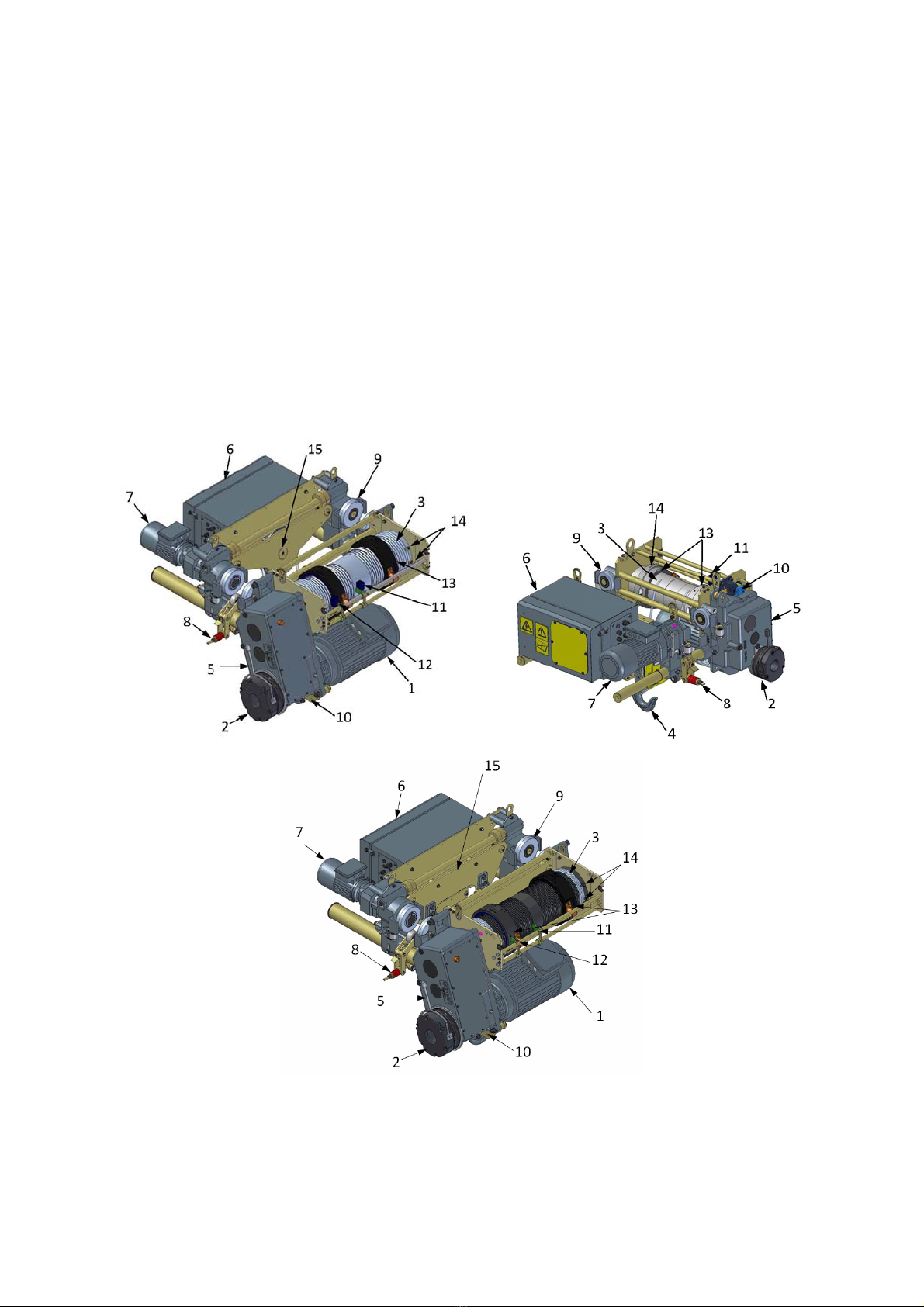
2DESCRIPTIONOFEQUIPMENT
TheZXserieshoistisoftheelectricallydrivenwireropetype.Thehoisthasamaximumloadthatitis
permittedtolift.ThisisreferredtoastheRatedCapacityorSafeWorkingLoad(SWL).Theratedcapacityis
clearlymarkedonthehoistnameplateandthebottomblock.
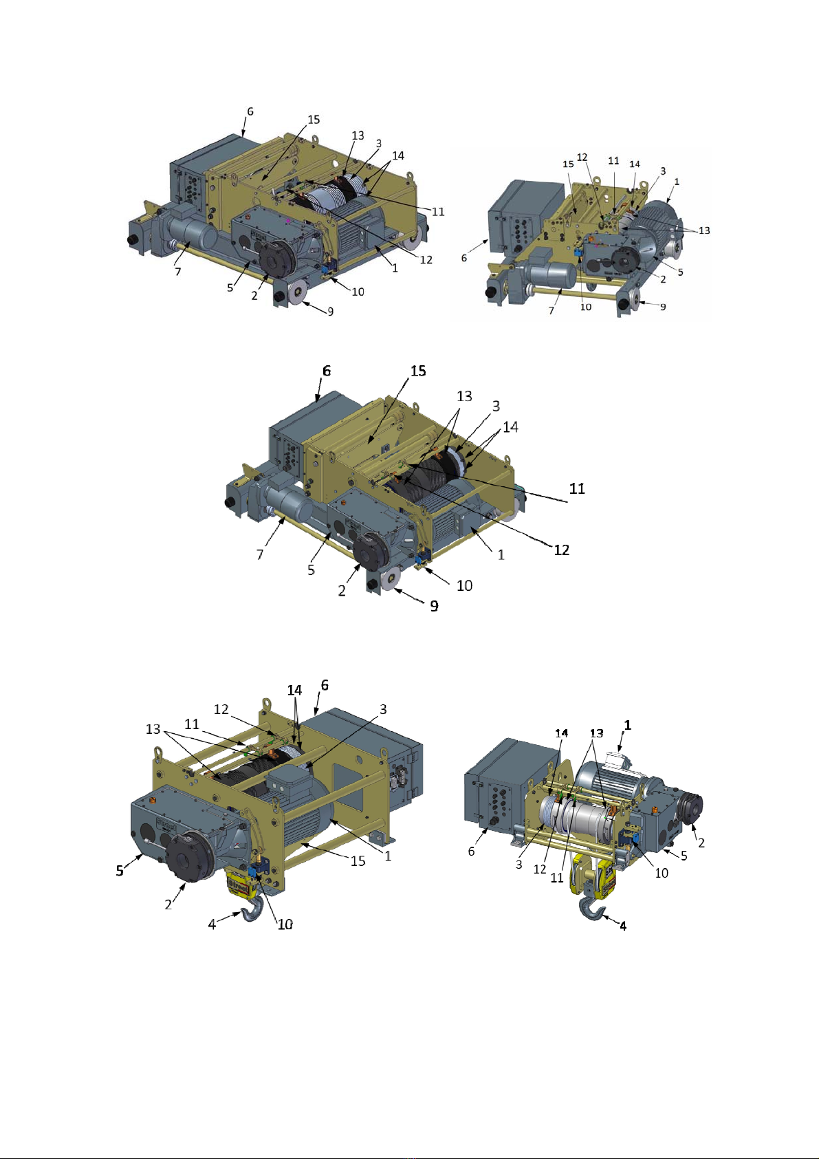
1.Hoistmotor6.Controlpanel 11.Upperlevellimitswitch
2.Hoistbrake7.Traveldrive 12.Lowerlevellimitswitch
3.Wirerope8.Reactionroller (LHonly) 13.Ropeguide
4.Bottomblock9.Travelwheels 14.Ropeclamps
5.Hoistgearbox10.Ratedcapacitylimiter 15.Sheaveassembly
ZX8‐4FALLLOWHEADZX6‐4FALLLOWHEAD
ZX8‐8FALLLOWHEAD
defgh
©StreetCraneCoLtd
Ref:D3256rev.BPage13of103
ZX8‐4FALLCRABZX6‐4FALLCRAB
ZX8‐8FALLCRAB
ZX8‐4FALLFOOTMOUNTZX6‐4FALLFOOTMOUNT

defgh
©StreetCraneCoLtd
Page14of103Ref:D3256rev.B
ZX8‐8FALLFOOTMOUNT
2.1 HOISTNAMEPLATE
Thehoistnameplateislocatedonthehoistendframeandcontainsthefollowinginformation:
Thehoistmodelcode.
Themanufacturersname.
Theserialnumber.
Theyearofmanufacture.
Hoistclassification.
Mechanismclassifications.
Theinformationonthisnameplatewillberequiredwhenorderingreplacementpartsandwhen
assessingtheremainingservicelifeofthehoist.Furtherinformationonthehoistmodelcodecanbe
foundinsection7.3.
Figure1–HoistNameplateLocation

defgh
©StreetCraneCoLtd
Ref:D3256rev.BPage15of103
2.2 LIMITINGDEVICES
Eachhoistisfittedwithupperandlowerlimitsandaratedcapacitylimiter(RCL).Theseareessentialitemsfor
thesafeoperationofthehoist.Additionallimitingdevicesmaybefittedifdeemednecessarybytherisk
assessment.
2.2.1 Hoistingandloweringlimits
Hoistingandloweringlimitswitchesarefittedtoallhoiststopreventthehookfromgoingtoohighand
damagingthehoistandfromgoingtoolowsoastoallowtheropestogoslack.Thesearesafetydevicesand
shouldNOTbeusedasanormalmethodofstoppingthehoist.Movementintheoppositedirection,atthe
speedselectedbytheoperator(sloworfast)isstillpossibleafterthenormallimithasbeentriggered.
1Certaincraneconfigurationsallowtheupperhookpositiontobesetatahigherlevelthanthe
undersideofthebridgegirders(doublegirdercranes).Insuchinstancestheoperatormust
takeextremecarewhenliftingtoensurethatadequateclearanceismaintainedbetweenthe
loadorliftingattachmentandthehoistorcranestructure.
Anoptionalsecondhoistupperlimitorultimatelimitmayalsobefittedifdeemednecessarybytheuserrisk
assessment.
Theultimatelimitisanemergencylimitemployedonlyifthenormalupperlimitfails.Oncetripped,thelimit
mustbemanuallyre‐setbyserviceormaintenancepersonnelandwillrequirethehookblocktobelowered
manuallyandthelimitre‐set.Ifthesecondhoistupperlimitoperates,thehoistshouldbetakenoutofservice
untilthereasonforthenormalupperlimitswitchfailurehasbeeninvestigated.Thefailureshouldberectified
beforeputtingthehoistbackintoservice.
Thesecondhoistupperlimit,whentripped,willpreventmovementfromallhoistandtraversemotions.The
travelmotion(longtravel)willremainfullyoperable.
Aredwarninglightonthebaseofthecontrolpanelwillilluminatetoindicatewhenthesecondultimatelimit
hasbeenactivated.
2.2.2 Ratedcapacitylimiter(RCL)
Allhoistunitsarefittedwitharatedcapacitylimiter(RCL)topreventtheliftingofloadsbeyondthecapacityof
thehoist/crane.IftheRCListrippedthehoistmotionwillstopanditwillthenonlybepossibletomoveinthe
lowerdirection.
2.2.3 Travel/Traverselimits(optional)
Limitswitchesattheextremesoflongandcrosstravelareoptionalbasedontheuser’sriskassessment.There
arethreetypes:‐
1. Onreachingthelimitthecraneorhoisttravelmotionwillstopaltogether.
2. Onreachingthelimitthecraneorhoistwillchangefromfasttoslowspeedandproceedatslow
speeduntiltheendstopisreached.
3. Ifatwostagelimitisfitted,onreachingthefirststagethemotionwillreducetoslowspeed.On
reachingthesecondstagethemotionwillstop.
Operationofthelimitdoesnothaveanyeffectonothercranemotions.Movementintheoppositedirection,
atthespeedselectedbytheoperator(sloworfast)isstillpossibleafterthelimithasbeentriggered.

defgh
©StreetCraneCoLtd
Page16of103Ref:D3256rev.B
3INSTALLATIONANDCOMMISSIONINGINSTRUCTIONS
Installationandcommissioningofthehoistmustbecarriedoutbyacompetentperson(s).Werecommend
thatinstallationandcommissioningarecarriedoutbyStreetCraneCompanyortheirapprovedagents.
Immediatelyreportanydamagewhichmayhaveoccurredduringtransit.Consultwiththemanufacturer/
supplierandrepairtheequipmentbeforeinstallation.Donotinstalldamagedequipment.Useonlyoriginal
StreetCranesparepartsforrepairs.Donotcarryoutanyalterationsormodificationstothehoisteitherprior
toorduringinstallation.
Ifthehoistislocatedoutdoorswerecommendthatasmallcover(roof)isfittedtotherunwaybeamtoprotect
thehoistatitsparkingposition.
3.1 TRAVERSEENDSTOPS
Singlegirder4&8falllowheadhoistsrequireendstopstobemountedoneitherendoftherunwayand
includerubberbuffersasshown.WeldonendstopscanbeprovidedbyStreetCrane.(PartNo.270‐31).
Figure2–SingleGirder4&8FallTraverseEndStops
Doublegirdercrabunitsaresuppliedfittedwithrubberbuffers.Suitableendstopsshouldbepositionedat
eitherendofthecrabrails.WeldonendstopscanbeprovidedbyStreetCrane.(PartNo.27‐20061).
Figure3–DoubleGirderTraverseEndStops

defgh
©StreetCraneCoLtd
Ref:D3256rev.BPage17of103
3.2 RUNNING&MOUNTINGSURFACETOLERANCESANDFINISHES
3.2.1 TolerancesontheInclinationoftheRunningSurface
Theangleofinclinationoftherunningsurfaceforthehoistshouldnotexceedthevaluesshown.
3.2.2 TolerancesonCrabRailGauge&RailHeight
Thegaugeshallnotdeviatefromthenominalbymorethan3mm.Thedifferenceinrailheightshallnotexceed
3mmforgaugesuptoandincluding2000mmor5mmforgaugesgreaterthan2000mm.Railheightshouldbe
aminimumof30mm.
3.2.3 TolerancesonSingleGirderRunwayFlangeWidth
Thevariationinthewidthofasinglegirderrunwayflangeshouldbenogreaterthan3mmoveritsentire
length.
3.2.4 TolerancesonMountingSurfaceforFootMountedHoists
Theverticalmisalignmentbetweenallmountingholesshallnotexceed1mm.
defgh
©StreetCraneCoLtd
Page18of103Ref:D3256rev.B
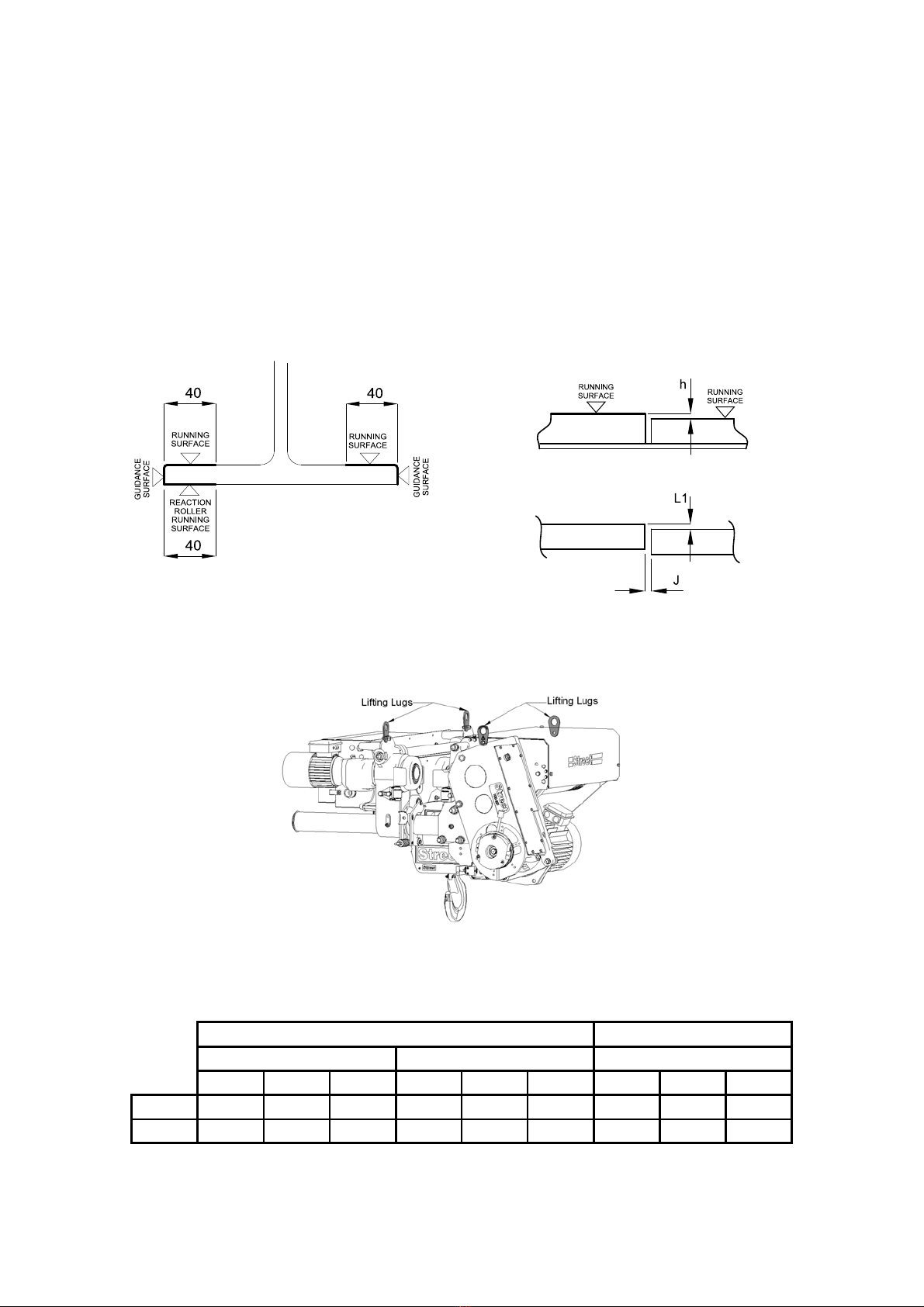
3.2.5 Toleranceonmisalignmentofrailjoints,wheelrunningsurfacesandguidancesurfaces
Therunningsurfaceforthehoistwheelsandguiderollers(singlegirderhoistonly)shouldbefreefrom
obstructionsandleftunpainted.Thesesurfacesshouldalsobefreefromdamage,pitting,weldbeadsorother
surfacedefects.
Surfacesshouldbealignedtoprovideasmoothtransitionpathforthewheelsbetweentracksections.
Gapsinanyjoints(‘J’)shouldbenogreaterthan2mm.
Thereshouldbenostepintherunningorguidancesurface(‘h’)greaterthan0.5mm.
Lateralmisalignmentindoublegirderrailjoints(‘L1’)shouldnotexceed1mm.
NOTE:RunwayjointspliceplatesonthebottomflangearenotpossiblewithZX6&ZX8singlegirderlow
headroomhoistsbecauseofthehoistreactionroller.
Figure4
–
SingleGirderRunwayTolerances Figure5
–
DoubleGirderRunwayTolerances
3.3 HOISTWEIGHTSANDLIFTINGPOINTS
3.3.1 LowHeadroom
Figure6
–
LowHeadroom4&8 FallLiftingPoints
3.3.1.1 Tableofweights‐LowHeadHoists
Ø8RopeØ13Rope
4Fall8Fall4Fall
NBLBELBNB LB ELB NB LBELB
ZX6353379423 ‐‐‐ ‐‐‐ ‐‐‐ ‐‐‐ ‐‐‐ ‐‐‐
ZX884489510409189921140886 9361106
Weightsshownforeachmodelinkgdonotincludeanyoptionalextras
1TheliftinglugsfittedtothehoistunitaredesignedforliftingthemassofthehoistunitONLY
(includinganytransportationfeet).

defgh
©StreetCraneCoLtd
Ref:D3256rev.BPage19of103
3.3.2 DoubleGirderCrab
Figure7
–
Double GirderCrabLiftingPoints
–
4&8fallunits
Doublegirdercrabunitshaving4or8fallsshouldbeliftedusingtheliftingpointsfittedtothehoistendframe
seeFigure7.
Afterliftingiscompleted,refitthehoistcovertopsectionandtightensetscrewsto15Nm.
3.3.2.1 Tableofweights‐DoubleGirderCrab
Ø8Rope Ø13Rope
4Fall8Fall 4Fall
NBLBELB NB LB ELB NB LBELB
ZX6405441499 ‐‐‐ ‐‐‐ ‐‐‐ ‐‐‐‐ ‐‐‐‐ ‐‐‐‐
ZX8PARALLELARRANGEMENT(…CRB…)
1400
GAUGE97310451237106411631373101511211303
ZX8PERPENDICULARARRANGEMENT(…CRE…)
1400
GAUGE965 ‐‐‐‐ ‐‐‐‐ 1056 ‐‐‐‐ ‐‐‐‐ 1008 ‐‐‐‐ ‐‐‐‐
2000
GAUGE100310561209109411741345104511331276
2600
GAUGE104010941246113112111382108211701312
Weightsshownforeachmodelinkgdonotincludeanyoptionalextras

defgh
©StreetCraneCoLtd
Page20of103Ref:D3256rev.B
3.3.3 FootMounted
Figure8–FootMountedLiftingPoints
3.3.3.1 Tableofweights‐FootMounted
Ø8Rope Ø13Rope
4Fall8Fall 4Fall
NBLBELB NB LB ELB NB LBELB
ZX6288314361 ‐‐‐ ‐‐‐ ‐‐‐ ‐‐‐ ‐‐‐
ZX8656714875731812985699790941
Weightsshownforeachmodelinkgdonotincludeanyoptionalextras
1TheliftinglugsfittedtothehoistunitaredesignedforliftingthemassofthehoistunitONLY.
This manual suits for next models
1
Table of contents


