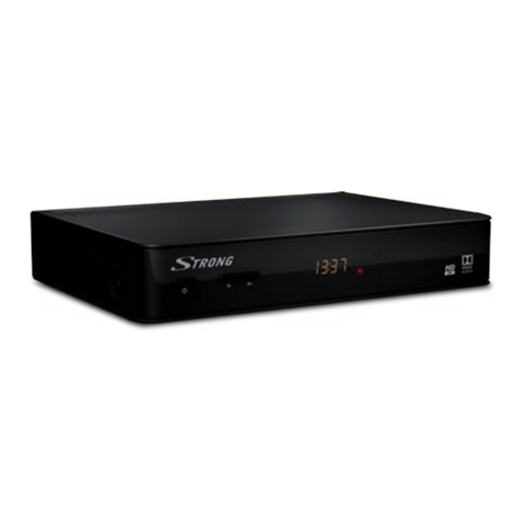
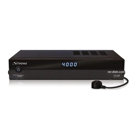
Strong SRT 4120 User manual

1
&OHMJTI
CONTENTS
CONTENTS .......................................................................... 1
1. GENERAL PROPERTIES ................................................. 2
2. SAFETY PRECAUTIONS ................................................ 4
2.1. POWER SOURCE ......................................................... 4
2.2. POWER CORD .............................................................. 4
2.3. LIQUIDS ........................................................................ 4
2.4. SMALL OBJECTS ....................................................... 4
2.5. CLEANING .................................................................... 4
2.6. VENTILATION .............................................................. 4
2.7. CAUTION ...................................................................... 5
3.PREPARING ...................................................................... 6
3.1. SATELLITE ANTENNA ................................................ 6
3.2. REMOTE CONTROL .................................................... 6
3.3. CONNECTIONS ............................................................ 6
3.3.1. CONNECTION TO T E TV ....................................... 6
3.3.2. CONNECTION TO SATTELLITE ANTENNA ............ 6
3.3.3. VCR SCART CONNECTION ..................................... 6
4. FRONT PANEL AND BACK PANEL ................................ 7
FRONT PANEL ................................................................ 7
BACK PANEL .................................................................. 7
5. REMOTE CONTROL ....................................................... 8
5.1 REMOTE CONTROL FUNCTION .................................. 9
5.2. STANDBY ON / OFF .................................................. 10
5.3. MENU ......................................................................... 10
5.4. TV / RADIO TOGGLE ( EXIT ) .................................. 10
5.5. UP / DOWN (CURSOR UP / DOWN) .......................... 10
5.6. VOLUME UP / DOWN (CURSOR RIG T / LEFT) ..... 10
5.7. LIST / PAGE UP (RED BUTTON) .............................. 10
5.8. AUDIO MODE SELECTIONS (YELLOW BUTTON) .. 10
5.9. INFO / ELP (? BUTTON) ......................................... 10
5.10. LANGUAGE KEY (MULTI AUDIO SERVICES) ........ 11
5.11. GUIDE KEY (ELECTRONIC PROGRAM GUIDE) ...... 11
5.12. FAVOURITE C ANNEL (BLUE BUTTON) ............... 11
5.13. SUBTITLE / PAGE DOWN (GREEN BUTTON) ........ 11
5.14. MUTE ........................................................................ 11
6. MENU INTERFACE ....................................................... 12
6.1. FIRST TIME INSTALLATION .................................... 12
6.2. MAIN MENU .............................................................. 12
6.3. C ANNEL ORGANISER ............................................ 12
6.3.1. NAVIGATING T E W OLE LIST OF C ANNELS 13
6.3.2. REORDERING T E LIST ........................................ 13
6.3.3. DELETING UNWANTED C ANNELS ..................... 13
6.3.4. RENAMING C ANNELS ........................................ 13
6.3.5. ADDING LOCKS TO C ANNELS .......................... 13
6.3.6. SETTING T E FAVOURITE LISTS ........................ 13
6.4. INSTALLATION MENU ............................................. 14
6.4.1. ANTENNA INSTALLATION MENU ........................ 14
6.4.2. FIRST TIME INSTALLATION................................. 15
6.4.3. ADD NEW C ANNELS ........................................... 15
6.4.3.1. AUTOMATIC SEARC ....................................... 15
6.4.3.2. MANUAL SEARC ............................................. 16
6.4.4. FACTORY SETTINGS ............................................ 16
6.5. SYSTEM SET-UP MENU ........................................... 17
6.5.1. MENU LANGUAGE ................................................. 17
6.5.2. AUDIO LANGUAGE ................................................ 17
6.5.3. SUBTITLE LANGUAGE ......................................... 17
6.5.4. TV TYPE ................................................................. 17
6.5.5. TV OUT .................................................................. 17
6.5.6. PARENTAL SETTINGS .......................................... 18
6.5.6.1. C ILD LOCK ....................................................... 18
6.5.6.2. MENU LOCK ....................................................... 18
6.5.6.3. C ANGE PIN ....................................................... 18
6.5.7. DATE TIME SETTINGS ......................................... 18
6.5.7.1. TIME .................................................................... 18
6.5.7.2. DATE .................................................................... 19
6.5.7.3. OFFSET UTC( ) .................................................. 19
6.5.8. ADVANCED / BASIC MENU ................................... 19
6.5.9. RECEIVER UPGRADE ............................................ 20
6.6. TIMER MENU ............................................................ 20
6.7. NO MENU ................................................................... 21
6.7.1. ELECTRONIC PROGRAM GUIDE (EPG) ............... 21
6.7.1.1. CURRENT EVENT MODE .................................... 21
6.7.1.2. NEXT EVENT MODE ........................................... 21
6.7.2. MESSAGES ............................................................ 22
6.7.3. C ANNEL NAVIGATION ........................................ 22
6.7.3.1. P+ / P- KEYS ....................................................... 22
6.7.3.2. NUMBER KEYS .................................................... 22
6.7.4. VOLUME CONTROL ............................................. 23
6.7.5. LIST MENU (RED BUTTON) .................................. 23
6.7.5.1. NAVIGATION ....................................................... 24
6.7.5.2. C ANNEL REORDERING .................................... 24
6.7.5.3. DELETING C ANNELS ....................................... 24
6.7.5.4. RENAMING T E FAVOURITE LIST .................... 24
6.8. DISEQC 1.2 SETUP MENU ........................................ 25
6.8.1. GOTO ANGLE ........................................................ 26
6.8.2. DRIVE MOTOR ....................................................... 26
6.8.3. MOTOR SPEED ...................................................... 26
6.8.4. SET EAST LIMIT ................................................... 26
6.8.5. SET WEST LIMIT ................................................... 26
6.8.6. ENABLE / DISABLE LIMITS .................................. 26
6.8.7. STORE SATELLITE POSITION ............................. 26
6.8.8. POSITIONER RESET .............................................. 26
6.8.9. RECALCULATE SATELITE POSITIONS ............... 26
6.9. SOFTWARE UPGRADE ............................................. 27
6.9.1 SOFTWARE UPGRADE T ROUG TV SCART ..... 27
6.9.2 RECEIVER UPGRADE OVER T E SATELLITE ...... 28
7. TROUBLE S OOTING GUIDE ...................................... 30
8. TEC NICAL SPECIFICATIONS ................................... 31
8.1. GENERAL C ARACTERISTICS ............................... 31
8.2. ARDWARE CONFIGURATION ................................. 31
8.3. DIGITAL CAPABILITIES ........................................... 31
8.4. REMOTE CONTROL ................................................. 32
8.5. LNB POWER SUPPLY ............................................... 32
8.6. AUDIO R / L ............................................................... 32
8.7. DIGITAL AUDIO ........................................................ 32
8.8. A / V & DATA IN / OUT ............................................. 32
8.9. SCART (TV, VCR) .................................................... 33
8.10. TV SCART SOCKET ............................................... 34
8.11. VCR SCART SOCKET ............................................ 34
9. CONNECTION DIAGRAMS .......................................... 35

2
&OHMJTI
1. GENERAL PROPERTIES
2000 Channels TV and Radio channels
6 languages menu system (English, German, French, Italian, S anish, Polish). Other languagesets, SET 2 (English,
Czech, Croatian, Hungarian, Slovak, Romanian) and SET 3 (English, Dutch, Turkish, Russian,Portuguese,
Bulgarian),available to download over the air and on com any web site.
Multi le Favourite Channel Lists (Favourite 1, 2, 3, 4)
Channel Lock
DVB Present/Next event information ( EPG )
5 timers for recording or as a slee timer
3 timer modes: daily, weekly, once
Parental lock at box and menu levels
Automatic search for all digital trans onders in the antenna
Su ort DiSEqC 1.2 u to 32 satellites
Selectable audio channel on audio out uts : Stereo, left or right
Multi language audio su ort ( u to 25 )
Teletext function su ort (VBI reinsertion)
Software u date via scart
Reset to factory settings function
Loo through VPS signal for VCR recordings ( in Standby mode )
C and Ku Band rece tion
LNB Control : Horizontal / Vertical olarity switching (18/13V +/- %7,5), 0-22 kHz switching, toneburst A/B switching
for dish selection, DiSEqC 1.0
Pre-installed FTA channels for Astra and Hotbird satellites
Signal strength bar and C/N estimator for antenna adjustment
Various channel search o tions
- Satellite search for reset trans onders
- Trans onder search
- Single channel search
- Network search
- Automatic search for newly added trans onders
- FTA search o tion for satellite and auto search modes
Auto FEC search,
Auto PID correction, (exce t user defined PIDs)
Auto channel name correction
Audio mute and volume control
CD Quality Sound

3
&OHMJTI
Zero-IF digital tuner
Frequency Range : 950 ~ 2150 MHz
In ut Signal Level : -25 ~ -65 dBm
Digital Decoding Pro erties
Demodulation : QPSK and FEC for 2~45 Ms s, SCPC/MCPC com atible
Video Decoding : MP @ ML, PAL/NTSC, 4:3/16:9
Video Out : PAL
Audio Decoding : MPEG Layer I & II, 32/44.1/48 KHz sam ling frequencies, single/dual
channels, stereo & joint stereo
System switching (TV/RADIO)
Last watched channel saving
LNB short circuit and overload rotection by software
IR remote control
Less than 7W ower consum tion in standby mode

4
&OHMJTI
2. SAFETY PRECAUTIONS
Please read the following recommended safety recautions carefully for your safety.
2.1. POWER SOURCE
The receiver should be o erated only from a 230 V AC, 50 Hz outlet. Please do not o en the cover by yourself. There
is high voltage in the set, which will danger your life. Please ask the closest service for hel .
2.2. POWER CORD
The ower su ly cord should be laced so that they are not likely to be walked on or inched by items laced u on
them or against them. Pay articular attention to cord where they enter the lug, ower outlet, and the oint where they
exit from the receiver.
2.3. LIQUIDS
Kee liquids away from the receiver. The receiver shall not be ex osed to dri ing or s lashing and no objects filled with
liquids, such as vases, shall be laced on the a aratus.
2.4. SMALL OBJECTS
Coins or other small objects must be ke t away from the receiver as they can fall through the ventilation slots of the receiver
and cause serious damage.
2.5. CLEANING
Disconnect the receiver from the wall socket before cleaning it. Use a dry cloth lightly dam ened (no solvents) to clean
the exterior of the receiver.
2.6. VENTILATION
Minimum distance of 10cm, from both sides and a distance of 15cm, to u wards around the a aratus should be ke t
for sufficient ventilation. Take care for a good air circulation. The ventilation slots should not be im eded by covering the
ventilation o enings with items such as news a er, tablecloths, soft furnishings, curtains, car ets, etc.

5
&OHMJTI
2.7. CAUTION
Please do not lace the set and remote control under direct sun light.
The set should be laced on a solid and safe base.
The location should not be selected as a room with high humidity, as the condensation, arising in the kitchen for exam le,
may cause malfunction or damage the set.
Heating or other thermal radiations under the set also may cause malfunction or damage the set.
The hot air, which arises during the o eration, should be ventilated with sufficient air circulation. Please do not ut the
set into closed areas and do not cover it.
Please avoid the contact of the set and remote control with water or humidity. Do not ut into o eration near bath,
swimming ools.
Connect the ower su ly of the receiver only after the installation is ready.
The arabolic antenna has to be grounded correctly. For this you have to follow the a ro riate VDE
regulations.
Take care to rovide good air circulation. Place the receiver in a location with adequate ventilation to revent heating
u of the receiver.
No naked flame sources such as lighted candles should be laced on the a aratus.
Never stack other electronic equi ment on to of the receiver.
Remove batteries from remote control when it is not to be used for a long eriod. Otherwise it can be damaged due to
any leakage of batteries.
6JGNKIJVPKPIHNCUJYKVJCTTQYJGCFU[ODQNYKVJKPCP
GSWKNCVGTCNVTKCPINGKUKPVGPFGFVQCNGTVVJGWUGTVQVJG
RTGUGPEGQHWPKPUWNCVGF FCPIGTQWUXQNVCIG YKVJKPVJG
RTQFWEV UGPENQUWTGVJCVOC[DGQHUWHHKEKGPVOCIPKVWFG
VQEQPUVKVWVGCTKUMQHGNGEVTKEUJQEMVQRGTUQPU
6JGGZENCOCVKQPRQKPVYKVJKPCPGSWKNCVGTCNVTKCPING
KU
KPVGPFGFVQCNGTVVJGWUGTVQVJGRTGUGPEGQHKORQTVCPV
QRGTCVKPICPFOCKPVGPCPEGUGTXKEKPIKPUVTWEVKQPUKP
VJGNKVGTCVWTGCEEQORCP[KPIVJGCRRNKCPEG
614'&7%'6*'4+5-1('.'%64+%5*1%-&1016
4'/18' 5%4'95 01 75'45'48+%'#$.' 2#465
+05+&' 4'('45'48+%+0) 61 37#.+(+'& 5'48+%'
2'45100'.
%#76+10
&101612'0
4+5-1('.'%64+%5*1%-
9#40+0)

6
&OHMJTI
3.PREPARING
3.1. SATELLITE ANTENNA
To have an excellent function of your digital set-to box, it is necessary to install the antenna correctly. Please avoid under
all conditions to have a short circuit at the antenna cable conductors (LNB receivers). Your digital set-to box is equi ed
with a LNB short-circuit rotection.
3.2. REMOTE CONTROL
First o en the battery cover on the underside of the remote control. Put on both batteries 1.5Volt (R03/AAA) referring
to the im rinted symbols (+/-) in the battery case and ut on the battery cover again.
While using the remote control, direct it towards the front side of the receiver. If the remote control do not work or the
chosen function could not be made, the batteries are most robably exhausted and they should be re laced as soon
as ossible. Please use only the leak roof batteries. It is the best to take out the batteries from remote unit in case
you wouldnt use the remote control unit for long time.
3.3. CONNECTIONS
3.3.1. CONNECTION TO THE TV
Connection over scart connector: Connect your set-to box with a scart cable using the TV scart connector on the rear
anel to your televisions scart connector (the one with RGB in ut, this is usually the first scart). If you use a scart
connector which does not have RGB in ut, you will not achieve the high erformance of your digital set-to box since
your TV will use com osite video signal instead of the RGB signals.
See Diagram 1 (Page 35)
3.3.2. CONNECTION TO SATTELLITE ANTENNA
Carefully lug in the connectors of the satellite antenna cables to the terminal of your set-to box labeled as LNB.
See Diagram 1 (Page 35)
3.3.3. VCR SCART CONNECTION
1) Connect one end of Scart cable to TV Scart connector on the STB and the other end of to a Scart connector on your
TV
2) Connect one end of Scart cable to VCR Scart connector on the STB and the other end of to a Scart connector on your
VCR
When the receiver is in standby mode:
When connected device (i.e., DVD, VCD) is switched on, the device will be automatically routed to TV.
When the receiver is on:
When connected device (i.e., DVD, VCD) is switched on, the device will be automatically routed to TV. Otherwise the
receiver will remain routed to TV. By ressing 0 button on the remote control receiver is routed back to TV manually.
Some devices which is connected to receiver do not su ort this feature. In this case routing rocess is done manually;
connected device is routed to TV by ressing 0 button on the remote control rovided that no menu on the screen. Then
TV is switched to AV mode manually. By ressing 0 button again receiver will be routed back to TV.
See Diagram 2 (Page 35)

7
&OHMJTI
4. FRONT PANEL AND BACK PANEL
FRONT PANEL
6WDQGE\/HG
,5,QIUD5HG
4120
' JLWDO6DWHOOLWH5HFHLYHUL
BAC PANEL
796&$57VRFNHW 9&56&$57VRFNHW
'LJLWDO$XGLR
2XWSXW63',)
9&579
$&9
+]
a
$8',2
/5
6$7,1 63',)
6XSSOLHGE\6WURQJ&R-DSDQ
/HIW5LJKW
$ DORJ$XGLR2XWSXW
6$7,1
$ WH D,1 $&
3RZHU&RUG

8
&OHMJTI
5. REMOTE CONTROL
0(18
$%&$%& '() *+,$%&$%& '() *+,
012 345
-./
678 9:; <=
$9
795$',2
3 3
9 9
/,67 )$9 68%7,7/(
*8,'( /$1*
"
0
2.

9
&OHMJTI
5.1 REMOTE CONTROL FUNCTION
1. STANDBY ON / OFF
2. DIGITS & LETTERS
3. MENU
4. TV / RADIO
5. CURSOR UP (P+)
6. CURSOR DOWN (P-)
7. CURSOR RIGHT (V+)
8. CURSOR LEFT (V-)
9. OK
10. FAVOURITE PROGRAM (BLUE BUTTON)
11. AUDIO MODE SELECTION (YELLOW BUTTON)
12. INFO / HELP (?)
13. LANGUAGE SELECTION (LANG.)
14. GUIDE (EPG MENU)
15. PROGRAM LIST / PAGE UP (RED BUTTON)
16. SUBTITLE / PAGE DOWN (GREEN BUTTON)
17. MUTE
18. AV
19. PROGRAM UP (P+)
20. PROGRAM DOWN (P-)
21. VOLUME UP (V+)
22. VOLUME DOWN (V-)

10
&OHMJTI
5.2. STANDBY ON / OFF
After making cable connections, the receiver goes out of
stand-by mode. After getting out of stand-by mode, the
receiver tunes immediately to the last watched/listened
channel.
When the STANDBY ON/OFF key on front anel is
ressed, it goes directly to the stand-by mode.
5.3. MENU
By ressing MENU key on the remote control, main menu
is accessed, MENU key will be also used to go out of the
menus (Channel Organiser, channel list, electronic
channel guide) to no menu or go out of the submenus to
u er menu.
“ ’’
and
“ ’’
are used to move u and down in the menus
to access the submenus. OK key on the remote control is
used to enter the submenu selected.
5.4. TV / RADIO TOGGLE ( EXIT )
When the TV/RADIO key is ressed either on the remote
control, the receiver changes mode (from TV to Radio or
from Radio to TV). When the mode is changed, receiver
tunes to the last watched / listened channel. In Radio
mode, if dis lay is available, oint at the end of 4 digit
dis lay glows.
There are s ecial TV and Radio icons in the channel banner
and channel info OSD.
TV/RADIO key will be also used to get out of the menus
and submenus to no menu.
5.5. PROGRAM UP / DOWN
When CHANNEL (CURSOR) UP/DOWN key is ressed
either on the remote control or on the front anel, the
receiver tunes to the next (res ectively revious) channel
in selected channel mode (in the channel organiser,
channel list or electronic channel guide menus, it tunes the
channel after OK key is ressed). If a channel that will be
tuned is locked, the user must enter the assword. If a
wrong assword is entered, (a banner will not warn the
user) it can not tune the desired channel, it can tune to the
revious or next channel by ressing P- and P+ keys
res ectively.
5.6. VOLUME UP / DOWN
When V+ or V- is ressed, either on the remote control or
on the front anel, a banner is dis layed, which shows
gra hically the resent volume. The sound is increased or
decreased by moving the cursor on volume scale by
ressing V+ and V- keys res ectively.
5.7. LIST / PAGE UP (RED BUTTON)
When the LIST key is ressed whole channel list or one of
4 favourite lists is dis layed. If the last watched/listened
channel is one of the favourite channels then the favourite
list in which the last watched/listened channel takes lace
is dis layed.
RED key is also used to dis lay channels age by age
in channel table and channel list, also to dis lay the
extended event information age by age in electronic
channel guide. The u er age is accessed with this key.
5.8. AUDIO MODE SELECTIONS
(YELLOW BUTTON)
The YELLOW key (LRS) will toggle the sound mode. The
mode is stereo as default. If the user wants to listen to only
the left or right audio channel, the sound mode can be
changed with this key. On single sound channel modes
(left or right channel) same sound channel will be switched
to both left and right out uts. When the mode is changed
an a ro riate OSD will be dis layed for a while. And this
will be stored for this channel to be able to switch to
requested audio mode next time.
5.9. INFO / HELP (? BUTTON)
When INFO (?) key is ressed an informative menu OSD
is dis layed. It gives information related to currently
watching channel. This info includes channel number,
channel name, channel mode (TV or Radio), trans onder
name, trans onder frequency, favourite list name (if the
channel is one of the favourite channels), audio mode,
whether the channel has teletext or not and short event
descri tion, additionally audio, video, and PCR PID values
of the channel.
INFO key is also used to show hel window which describe
some remote control functions in the menus according to
the menu function.
This hel window must be closed (by ressing INFO key
again) to be able to erform the o tions in the menu.

11
&OHMJTI
5.10. LANGUAGE EY
(MULTI AUDIO SERVICES)
The LANG. key allows selecting another sound track of the
resent channel. When the language key is ressed a
menu is dis layed showing the number of ossible audio
languages for TV and tracks for Radio channel available.
The user is allowed to navigate using P+, P- keys and
select with OK key. If an audio language su ort Dolby
digital out ut, AC3 ex ression is seen at the end of the
audio language name. If the channel does not have multi
audio, a o -u message will warn the user.
5.11. GUIDE EY
(ELECTRONIC PROGRAM GUIDE)
If the GUIDE key is ressed electronic channel guide
(EPG) menu is dis layed. This menu shows firstly the
current and by toggling (LEFT/RIGHT) the next events
information (start and end time for current and next events,
channel no, channel name, event name of the channels in
tuned trans onder).
This menu consists of a channel bar which shows time
scale from current time to 3 hours + current time. This bar
shows current/next event eriod in current/next event mode
as highlighted.
There is also an o tion for every channel to make user aware
that the next event starts, which is reminder. If the
reminder is set (by ressing OK key in next event mode
the clock symbol near the time scale will become
highlighted.) When that events start time is reached, a o
u message will a ear and if the user acce ts to change
the channel, receiver will switch to that channel.
5.12. FAVOURITE CHANNEL
(BLUE BUTTON)
Each channel can be selected as favourite from the channel
organiser menu; the user goes on the channel wanted to
mark as favourite, then Favourites is selected by ressing
“ ’’
key. The desired channel is added to one or several of
4 inde endent Favourite lists by ressing OK button on the
selected favourite. When Favourites frame is activated,
FAV button toggles between the favourites. The limit for the
number of favourite channels is 100.
In no menu mode, ressing FAV (blue button) on remote
control will cause the receiver to change the current
channel to the first favourite channel. The user can select
any channel in current favourite list by toggling ( ressing
“ ’’
and
“ ’’
keys) and other favourite lists by ressing FAV
button again. If there is no channel in any favourite list a
warning message is dis layed on screen.
If a channel has been locked by the lock code, the user
must in ut the assword. If a wrong assword is entered
(a banner will not warn the user) the desired channel can
not be watched and the revious or next favourite channel
can be watched by ressing P- and P+ keys and next
favourite lists can be selected by ressing FAV button
again.
FAV button must be ressed one more time to get out of
favourite channels.
5.13. SUBTITLE / PAGE DOWN
(GREEN BUTTON)
When the user resses SUBTITLE key, a menu OSD is
dis layed with language of default or first subtitle coming
from transmission. The language of subtitle can be
changed from this menu by toggling. If there is no subtitle
in that channel, None is dis layed in this menu. After the
user selects any of them, it starts to dis lay the a ro riate
subtitle on the screen. Selecting None from the subtitle
menu, disables subtitle dis lay.
This Green key is also used to dis lay channels age by
age in channel table and channel list, and also to dis lay
the event information age by age in electronic channel
guide. The next age is accessed with this key.
5.14. MUTE
When the MUTE key is ressed, mute symbol is dis layed
on the right side of the screen. The mute symbol will stay
until MUTE is ressed again, or V+, V- keys is ressed.
Mute function does not work in case of Dolby Digital (AC3)
out ut.
The mute symbol is not dis layed on the screen in case
of any menu dis layed.

12
&OHMJTI
6. MENU INTERFACE
6.1. FIRST TIME INSTALLATION
When the box is o ened from stand-by and there is no
channel stored in database, First Time Installation Menu
window is dis layed on the screen. In six languages it
writes, Welcome! Please select your language. The
a ro riate box language can be chosen by highlighting the
desired language (with
“ ’’
,
“ ’’
keys) and ressing OK.
After ressing OK, Antenna Installation Menu will be
dis layed. After you set the correct arameters as
ex lained in the Antenna Installation Menu, go to the Start
Scan line and ress OK.
Then choose Yes for Start Scan? The box will
automatically find the reset channels and store them.
6.2. MAIN MENU
Main menu is accessed, ressing the MENU key on the
remote control.
The items accessed through the main menu are:
Channel Table
Installation
System Set-u
Timers
6.3. CHANNEL ORGANISER
Following o erations can be erformed in this menu:
1. Navigating the whole list of channels
2. Reordering the list
3. Deleting unwanted channels
4. Renaming channels
5. Adding locks to channels
6. Setting the favourite lists

13
&OHMJTI
6.3.1. NAVIGATING THE WHOLE LIST OF
CHANNELS
While in the channel menu
“ ’’
,
“ ’’
(P+ / P-) keys serves
for moving focus to revious or next channel and Red/Green
(LIST/SUBTITLE) keys for age u and age down.
The trans onder frequency, olarisation and satellite name
of the selected channel are dis layed left bottom side of
the screen.
To watch a s ecific channel (highlighted channel), ress
OK while the Select art is highlighted. Then the selected
channel will be dis layed in the right-to corner of the
screen.
The scroll bar in middle of the screen shows relative
osition of the currently visible channel with res ect to the
whole list.
6.3.2. REORDERING THE LIST
Reordering can be done by moving the channels one by
one to new ositions. In order to do that Move button is
highlighted using
“ ’’
“ ’’
keys then channel to be moved
is selected by ressing OK, the colour of the channel will
be changed to ur le. In this state
“ ’’
,
“ ’’
keys will
re lace the channel with the revious or next channel.
Desired channel location can be ty ed as number and the
channel will be moved to that osition (if number entered
is greater than the max channel number then it is acce ted
as the max channel number). After youre satisfied with last
osition of the channel ress OK to finish moving channel.
If you want to cancel moving o eration ress MENU.
6.3.3. DELETING UNWANTED CHANNELS
To delete a channel, highlight it using
“ ’’
,
“ ’’
or Red/
Green buttons then highlight the Delete button using
“ ’’
“ ’’
keys and ress OK. A message dis layed to
confirm your decision, if you still want to delete select
YES button and ress OK once, deleting o eration will be
cancelled if NO o tion is selected or menu key is
ressed .
6.3.4. RENAMING CHANNELS
To rename a s ecific channel select it, then select the Edit
Name button using
“ ’’
“ ’’
keys and ress OK. The
name a ears now on the right side of the menu with the
first character highlighted.
“ ’’
“ ’’
keys moves to the revious/next character.
“ ’’
,
“ ’’
keys toggles the current character, i.e., b
character becomes c with
“ ’’
and a with
“ ’’
. The numeric
buttons from 0 to 9 re laces the highlighted character
with the character that corres onds to selected numeric.
The limit for the channel name is 15 character.
In this editing mode ressing Menu cancels the editing and
ressing OK saves the new name of the channel.
6.3.5. ADDING LOC S TO CHANNELS
Channel locking rovides a assword- rotected access to
channels selected by arents. In order to lock a channel
you should know the arental Lock assword (default
assword is 0000), then highlight the channel to be locked
and select the Lock button, when OK is ressed a
assword dialog is dis layed. Enter the arental lock code,
ress OK and then Lock icon will be dis layed in front of
the selected channel. Re eat the same o eration to
cancel the Lock.
If you forget the assword you can use the universal
assword (8277). Password can only be changed from the
Configuration Menu.
6.3.6. SETTING THE FAVOURITE LISTS
Favourite lists rovide an easy way to grou channels. Four
favourite lists are available as Favourite1, Favourite2,
Favourite3 and Favourite4. The names of the favourite lists
can be changed from the List menu. In the Channel Table
menu the channels can only be added or removed from a
s ecific favourite list. Reordering the channels in a favourite
list can only be done from the favourite list menu.
In order to add or remove a channel from a favourite list,
highlight the Favourites button using
“ ’’
“ ’’
keys, the
favourite submenu will be dis layed. Then select the
channel to be added/removed to/from the favourite list
using
“ ’’
,
“ ’’
or Red/Green buttons, choose the favourite
list name (in which the channel will be added) from the list
menu by using the FAV key then ress OK. The favourite
channel icon will be dis layed or removed in/from the
selected channel bar. Pressing Menu key saves all your
settings.
If you want to add that channel to Favourite2,3, or 4, you
should ress FAV button in order to navigate through
favourite o tion. Then ress OK button.

14
&OHMJTI
6.4. INSTALLATION MENU
The Installation menu mainly intends to hel you for setting
your antenna configuration and building a Channel Table
into your receiver in most efficient way.
This menu includes:
1. Antenna Installation
2. First Time Installation
3. Add New Channels
4. Factory Settings
6.4.1. ANTENNA INSTALLATION MENU
It is an advanced ty e menu and hel s you to set & store
your antenna configuration to a ro riate satellite (ASTRA,
HOTBIRD...). Antenna Installation menu shows all stored
satellites with their names and configurations. There are
totally 32 satellites -some are resets-, you can edit &
store or scan any satellite by using dedicated keys.
After entering Antenna Installation menu, the following
arameters is dis layed:
Satellite Name (Preset names and others): Currently 27
reset satellites exist as Astra, Hotbirdetc. and 5 user
defined satellites as User1User5 a end to them. The
satellites can be renamed by remote control.
Low Frequency: You should set this value according to low
oscillator frequency of your LNB device (by default 9750 for
Universal LNB).
High Frequency: You should set this value according to
high oscillator frequency of your LNB device (by default
10600 for Universal LNB).
Polarisation: You can select antenna olarisation as
Horizontal, Vertical or both (H/V).
22 kHz: You can select frequency band as low or high by
choosing Off or On res ectively. If you select Auto, receiver
decides 22KHz On or Off de ending on frequency.
DiSEqC (Off / Tone A / Tone B / DiSEqC 1 / DiSEqC 2 /
DiSEqC 3 / DiSEqC 4): You should set this according to
switch osition of the desired satellite; if your LNB device
is connecting directly to your receiver we advise you to
select Off mode.
LNB Power: You can enable/disable LNB su ly, this must
be set to On if the receiver is not connected to other box
via loo - through.

15
&OHMJTI
Exce t satellite name, all arameter values are de endent
to satellite name so when you toggle this button, the whole
arameters are u dated automatically. To give an idea
about the signal level, or you can say ower level, there is
a Signal Level indicator in this menu. It u dates after you
change any arameter. For all items o eration is the same,
after highlight the item and change value by toggling (by
ressing
“ ’’
/
“ ’’
keys).
After ressing Start Scan the user will be asked whether
he would like to start scan or not? By ressing OK, all
channels and channels ( redetermined in database) of that
satellite will be searched and stored into receiver, this
o eration is called as Preset Search.
6.4.2. FIRST TIME INSTALLATION
It is an advanced ty e menu. A Welcome! window a ears
on the screen after warning message to ask to user
whether he wants to delete all channels (To delete all
channels means clearing the database) or not, this window
includes welcome messages in all languages and user
selects the language. Then Antenna Installation Menu is
dis layed and the user selects the satellite name and other
s ecifications to find out channels. After ressing Start
Scan the values entered are stored to that satellite. And
the user will be asked whether he would like to start scan
or not? By ressing OK, all channels ( redetermined in
database) of that satellite will be searched and stored into
receiver and channel table is u dated.
6.4.3. ADD NEW CHANNELS
After highlight the Add New Channels by ressing u /down
keys, ress OK button or right key.
This menu includes:
1. Automatic Search
2. Manual Search
6.4.3.1. AUTOMATIC SEARCH
The user can scan some or all satellites for only free to air
or all channels by this menu. Menu items:
Satellite Name: The satellite selection is made by toggling.
Symbol rate1/2/3: Additional symbol rates for newly added
trans onders are entered directly by 0,1,2, 9 keys.
For every well-known satellite like ASTRA, HOTBIRD
there is a symbol rate table, which is formerly stored into
receiver. So the scan function is erformed according to this
table or additional symbol rates if there exist.
After search, if new channels are found, they are added to
the channel table.

16
&OHMJTI
6.4.3.2. MANUAL SEARCH
It is an advanced ty e menu. Menu items:
1. Satellite Name
2. Polarisation
3. Frequency
4. Symbol rate
5. Network Search
6. PID Entry (for single channel search)
Satellite Name, Polarisation values and Network Search
requirements are changed by toggling. Frequency and
Symbol Rate are entered directly using 0,1,2,.,9 keys.
Video, Audio and PCR PIDs of the desired channel can be
also entered by PID Search menu is selected. Every
channel has its own PID values, so by entering PID values,
only one channel can be find. By ressing OK, the values
are stored and after searching if a new channel exists they
are a ended to the Channel Tables. Found channel name
is shown as Pgm.
As soon as entering trans onder frequency, changing
a ears in the signal strength bars (Signal Level and Signal
Quality bars) at the bottom of the menu. Signal Level bar
shows the strength of the digital signal. Signal Quality bar
shows lock quality of the device for entered values.
If Network Search item selected as YES, the arameters
of all trans onders will be collected from NIT (Network
Information Table) and the tuning will be erformed.
When tuning in the screen there will be shown the satellite
name and frequency, olarization, symbol rate of the
current trans onder under the found rograms.
As shown below there will also be dis layed a rogress bar
which indicates the ercentage of searched trans onders.
If include scrambled channels item selected as
YES,scrambled channels will be also searched.
Outherwise only FTA channels will be searched.
6.4.4. FACTORY SETTINGS
The user can use this item to load reset channel table and
default settings, which had been loaded to receiver at the
factory. To start factory settings, highlight this item and
ress OK key. Then a message is dis layed to warn the
user like Are you sure to DELETE ALL services and
LOAD DEFAULT channel table? The user can confirm by
OK key or abandon by MENU key (or by selecting NO).

17
&OHMJTI
6.5. SYSTEM SET-UP MENU
The user can configure the settings of the box. Select
System Set-U from Main Menu and ress OK to enter this
menu. There are two modes: Basic & Advanced. If the
advanced menu is active, by selecting Basic Menu basic
menu can be made active or vice versa.
System Set-U Menu includes the following main items:
Basic Mode Advanced Mode
Parental Settings Menu Language
Date Time Settings Audio Language
Advanced Menu Subtitle Language
Software Version V1.0.0 TV Ty e
TV Out
Parental Settings
Date Time Settings
Basic Menu
Software U grade
Software Version V1.0.0
6.5.1. MENU LANGUAGE
It is the language used in Menus. By ressing
“ ’’
/
“ ’’
keys Menu Language o tion is highlighted. The current
menu language can be changed and u dated by
“ ’’
/
“ ’’
keys.
6.5.2. AUDIO LANGUAGE
By ressing
“ ’’
/
“ ’’
keys Audio Language o tion is
highlighted. The current audio language can be changed
and u dated by
“ ’’
/
“ ’’
keys. Changes will be u dated
while exiting System Set-u Menu. When new channels are
added, they are recorded with the default audio language
in database.
6.5.3. SUBTITLE LANGUAGE
By ressing
“ ’’
/
“ ’’
keys Subtitle Language o tion is
highlighted. The current subtitle language can be changed
and u dated by
“ ’’
/
“ ’’
keys. Changes will be u dated
while exiting System Set-u Menu.
6.5.4. TV TYPE
By ressing
“ ’’
/
“ ’’
keys TV Ty e o tion is highlighted.
TV as ect ratio can be changed using
“ ’’
/
“ ’’
keys. TV
as ect ratio can be selected between 4:3 or 16:9.
6.5.5. TV OUT
By ressing
“ ’’
/
“ ’’
keys TV Out o tion is highlighted.
The current TV Out ty e can be changed and u dated by
“ ’’
/
“ ’’
keys. The icture quality in RGB is better than
CVBS.

18
&OHMJTI
6.5.6. PARENTAL SETTINGS
By ressing
“ ’’
/
“ ’’
keys Parental Settings o tion is
highlighted and by ressing OK it is selected. The
assword container to enable the Lock Code is dis layed.
Factory default assword is set to value "0000". If the
assword is entered correctly, Parental Settings Menu is
dis layed including following items:
1. Child Lock
2. Menu Lock
3. Change PIN
6.5.6.1. CHILD LOC
The user can set/reset Child Lock by selecting Enabled/
Disabled. If the Child Lock is enabled, unwanted users
cant use the front anel buttons. To be able to use the front
anel buttons, Child Lock must be disabled again.
Changes will be u dated after exiting MENU.
6.5.6.2. MENU LOC
The user can set/reset Menu Lock by selecting Main Menu
/ Installation / Disabled. If the Menu Lock is disabled, all
menus are unlocked. If the Main Menu o tion is selected,
Main Menu can not be accessed. If the Installation o tion
is selected, Installation Menu can not be accessed. To
access the desired menus, correct assword must be
entered.
or
6.5.6.3. CHANGE PIN
The assword can be changed by selecting Change PIN
o tion. After ressing OK button new assword menu is
dis layed. New assword is entered using 0,1,2,9
keys. The new assword must be confirmed for security.
If both asswords are four digits long and the same,
assword is changed.
It is u dated after exiting Parental Settings Menu.
If you forget the assword, you can enter locked channels
and menus and change assword by using the universal
assword (8277).
6.5.7. DATE TIME SETTINGS
By ressing
“ ’’
/
“ ’’
keys Date Time Settings o tion is
highlighted. By ressing OK Date Time Settings Menu
dis layed, it includes following items:
1. Time,
2. Date,
3. Offset UTC(h).
The actual date as day, month and year; time as hour and
minute; UTC as hour are entered. After first booting of the
box the values are 00:00 / 01.01.2001 / 0 and the actual
time, date, and offset to Universal Time Coordinated (UTC)
can be entered by
“ ’’
/
“ ’’
and 0,1,2,...,9 keys.
After first booting the receiver, as soon as get the UTC time
from the Satellite, u dates the time. The user doesnt have
to enter the time settings manually.
6.5.7.1. TIME
By ressing
“ ’’
/
“ ’’
keys Time o tion is highlighted and
actual time can be entered by NUMBER keys. The time
entered must be valid otherwise digits are ski ed. By
ressing MENU key to return System Set-u Menu, time
is u dated.

19
&OHMJTI
6.5.7.2. DATE
By ressing
“ ’’
/
“ ’’
keys Date o tion is highlighted and
current date can be entered by NUMBER keys. The Date
entered must be valid otherwise digits are ski ed. By
ressing MENU key to return System Set-u Menu, date
is u dated.
6.5.7.3. OFFSET UTC(H)
By ressing
“ ’’
/
“ ’’
keys Offset UTC(h) o tion is
highlighted and time offset can be toggled with
“ ’’
/
“ ’’
keys. Time offset will be changed just after the offset is
toggled. Time will be also u dated according to the new
time offset. By ressing MENU key to return System Set-
u Menu, time and offset UTC(h) is u dated.
6.5.8. ADVANCED / BASIC MENU
By ressing
“ ’’
/
“ ’’
keys Basic Menu / Advanced Menu
o tion is highlighted and by ressing OK, if the advanced
menu is active, basic menu will be made active and vice
versa.

20
&OHMJTI
6.5.9. RECEIVER UPGRADE
By ressing OK Receiver U grade menu is entered. Detail
information about Receiver U grade Menu is in section
6.9.2
6.6. TIMER MENU
By ressing
“ ’’
/
“ ’’
keys in Main Menu, Timers is
highlighted and by ressing OK, Timer Menu is entered.
There is a five column summary information, such as timer
no, channel name, start time, end time, start date and
mode, for each of the five timers.
There are two ways to set a timer. If the Start / End time and
Date are valid values, the timer can be set directly by
changing the mode to Active from Inactive using
“ ’’
/
“ ’’
keys.
If the Start / End times and Date are invalid or if the set
values will be changed totally, OK must be ressed while
the desired timer is highlighted in the summary list. A new
window where the timer details will be entered is dis layed
on the lower art of the screen. The timer details are as
follows:
Ty e: By using
“ ’’
/
“ ’’
keys, channel ty e, i.e., TV or
Radio is selected.
Name: According to the ty e that is chosen above,
“ ’’
/
“ ’’
keys will navigate the user through the TV or Radio list
and name of the channel is selected.
Start: By using 0,1,2,9 keys start time of the timer is
entered.
End: By using 0,1,2,9 keys end time of the timer is
entered.
Date: By using 0,1,2,9 keys date of the timer is entered.
Mode: By using
“ ’’
/
“ ’’
keys, timer mode is selected as
Once, Daily or Weekly .
The current time and date are shown on the lower-right art
of the screen to hel the user.
After the desired detail fields are filled, by ressing OK the
settings are saved, by ressing MENU new settings are
cancelled and the user turns back to timer menu. A Timer
setting is cancelled (disabled) by changing the mode to
Inactive in Timer Menu.
When a timer Start time is reached, the receiver switches
to the desired channel, then when the End time is reached,
the box goes to stand-by mode. This utility hel s the box
to be used as a slee -timer.
Other manuals for SRT 4120
1
Other Strong Receiver manuals

Strong
Strong PrimaSat II User manual

Strong
Strong SRT 7000 User manual

Strong
Strong SRT 5495 User manual

Strong
Strong SRT 630WS User manual

Strong
Strong PrimaSat II User manual

Strong
Strong STR 8106 User manual

Strong
Strong SRT 7511 User manual

Strong
Strong SRT 7806 User manual

Strong
Strong SRT 7100 User manual

Strong
Strong SRT 7501 User manual

Strong
Strong SRT 8910 Operating instructions

Strong
Strong SRT 7510 User manual

Strong
Strong SRT 7004 User manual

Strong
Strong SRT 4922B+ User manual

Strong
Strong SRT 8209 User manual

Strong
Strong SRT 8211 User manual

Strong
Strong SRT 51 User manual

Strong
Strong SRT 7010 User manual

Strong
Strong SRT 4668X User manual

Strong
Strong SRT 5120 User manual