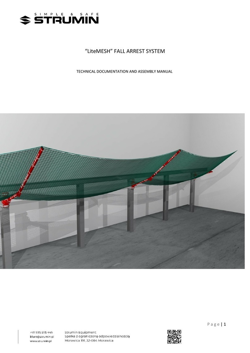
STRUMIN LiteMESH User manual

HOME
P a g e | 2
ATTENTION !
TECHNICAL DOCUMENTATION
BEFORE EVERY USE OF THE “LiteMESH” SYSTEM, THE USER SHALL READ THIS TECHNICAL
DOCUMENTATION AND ALWAYS STRICTLY FOLLOW THE RULES DESCRIBED HEREIN. THESE
INSTRUCTIONS WERE PREPARED FOR ALL WORKERS AND PEOPLE THAT WILL WORK ON
TRANSPORTING, UNLOADING, ASSEMBLING, DISASSEMBLING, STORING, CHECKING AND ANY
OTHER WORKS CONNECTED TO THE SYSTEM.
EVERY USER IS OBLIGED TO READ AND GET FAMILIAR WITH THE SYSTEM’S TECHNICAL DOCUMENTATION!
CONTENTS:
INTRODUCTION
1.0 MANUFACTURING BASIS
2.0
USER MANUAL
2.1
TERMINOLOGY AND DEFINITIONS
2.2
PURPOSE AND SCOPE OF USAGE
2.3
WORKING PARAMETERS
2.4
RULES FOR SAFE OPERATION
2.5
TECHNICAL INSPECTION
2.6
MAINTENANCE
2.7
QUALIFICATIONS OF THE PEOPLE USING THE SYSTEM.
2.8
CONNECTING THE SYSTEM WITH A SLING.
2.9
INSTALATION OF THE SYSTEM.
2.10
DISASSEMBLING AND MOVING THE DEVICE BETWEEN WORKPLACES.
2.11
USE OF THE SYSTEM.
3.0 DEVICE’S REGISTER
4.0 RATING PLATE
5.0 TABLE: DANGER RISK PROTECTION
6.0 DESIGNER’S STATEMENT EU
DECLARATION OF CONFORMITY

HOME
P a g e | 3
INTRODUCTION
INTRODUCTION This technical documentation contains the guidelines concerning the proper use of
THE SYSTEM. Workers and other people using the system shall always observe the guidelines
contained herein. In case of any events not described in this document, the occupational safety and
health regulations and other regulations, appropriate to the specific situation, shall be observed.
It is forbidden to modify the system in any other way than described in the Technical
Documentation. The manufacturer is not liable for any modifications in the system in a
way that is not described in the technical documentation.
1. MANUFACTURING BASIS
The LiteMESH system is aimed at increasing the safety of works performed at heights.
The design of the LiteMESH system was drawn in accordance with the
applicable laws and technical norms:
EN-1263-1_2015-02E – Temporary constructions used at a working site.
Safety nets,
EN 1090-2..2012,
EN ISO 13920:2000.

HOME
P a g e | 4
2.0
USER MANUAL
2.1
TERMINOLOGY AND DEFINITIONS
Module:
The main part of the system that consists of a console to which the safety net is
assembled.
Console:
An element through which the net is assembled and formed. The console consists of
a universal assembly holder and a moveable arm.
Console's arm:
A moveable element consisting of two arms joined with a swivel joint. It allows to form
the shape of the safety net. The net and its edge line is assembled to the movable arms
and its edge line.
The universal assembly holder:
A holder used to assemble the moveable arm to the floor or the wall. It is also used in
case of the console's assembly adapters – “H” adapter. The holder allows to assemble
the moveable arm in lower configurations (see the Assembly Manual).
Stretching holder:
An additional holder used while attaching the net’s edge to the floor or wall –
depending on a given situation. That holder is used also during the assembly of the
stretches of the extreme consoles.
Assembly adapter “H”:
A device used to assemble the console to the elements of the construction. i.e. balks,
poles etc. in situations when there is no possibility to drill and perform other actions
that would interfere with the building's structure.
Net:
The net consists of two integrated nets of which one is used to catch large objects and the
other one (mosquito net) catches smaller elements. The net used in the system was designed
in accordance with the EN-1263- 1_2015-02E standard:
TYPE S, A2 Q100. It means that it is an A2-class net that absorbs min. 2300 J of
energy. The allowed maximum fall height for objects is below 2 m.
The net consists also of the edge line that works as an intermediate element carrying the
loads from the net to its outer edge and the carrying elements of the system.
Edge line:
Along the edge of the net there is an integrated polypropylene line (Ø12 and
the strength of 30 kN).
Stretching line (lace up):
A Ø8 polypropylene line for connecting the nets (lace up – see the assembly manual).
It is also used for adjusting the tension of the most extreme consoles.

HOME
P a g e | 5
2.2
PURPOSE AND SCOPE OF USAGE
The LiteMESH system is aimed at securing the outer edges of buildings and used as a
protection measure while performing works on lower levels and to secure
communication strings.
The net catches falling objects and protects people standing below.
The LiteMESH system is a connection of two nets with wide and small meshes. It catches both big
and small objects, and even semi-liquid elements. The system is characterised by an easy, universal
and quick assembly to the front and the upper part of a floor, as well as to a wall. Thanks to the
lightness and flexibility of the system, it is possible to adjust it to all building conditions.
The LiteMESH net is a quick and an affordable way to secure construction sites
and works which demand increasing the level of safety.
The use of the LiteMESH system is allowed only on condition that the user adheres to this
Technical Documentation, as well as the proper occupational safety and health regulations.
2.3
ALLOWED WORKING PARAMETERS
The LiteMESH system is a set of elements working together to protect users from falling. For
that reason and in order to use it in a safe manner, it is necessary to get familiar with the rules
of the system's operation and its limitations.
The maximum offset between the consoles: 6 m,
the maximum catching height 2 m,
the maximum distance between the edge line's holders: 3 m,
the nominal value of the energy absorbed by the net: 2,3 kJ.

HOME
P a g e | 6
During the operation of the SYSTEM, workers shall bear in mind the safety of the users,
any personnel or people that may be affected by the operation of the device.
2.4
RULES FOR SAFE OPERATION
The LiteMESH system shall be used only for the purposes described in this manual. Any use not in
compliance with this manual entails the risk of accidents and poses a threat to health and life.
Any use not in compliance with the Technical Documentation voids the guarantee.
The device is used to catch falling objects which may pose a threat for any people standing
below the working area. In case on an improper use of the system, it poses a risk for the user as
well as the other people near the user.
Before using the LiteMESH system, the worker shall read this manual.
During the use of the LiteMESH system, the workers shall meet all the requirements described in the
Technical Documentation and in any laws and regulations that apply.
Any works connected to the assembly, elements installation
and anchoring to the floor lie within the responsibility of the site manager.
The whole scope of works connected to the everyday use of the product lies within the responsibility
of the site manager.
Such actions like a daily and weekly inspection of the system shall be
entered into a system's control card.
After an accident that resulted in damaging any elements of the system, it should be
immediately withdrawn from further use. The damaged elements shall be replaced with new
elements.
Before using the FALL ARREST SYSTEM , the users shall read the technical documentation
of the system.
-
Shall not stand within the range of the DEVICE
during transport.
-
Shall remove any elements not connected to the given work which may pose a threat (cables,
hoses, unnecessary material).
-
The device shall not be used as a provisional platform, as it was not designed to carry
continuous loads or storing objects.
-
The place where the LiteMESH system is used shall have a rescue plan implemented, in
case of an event that led to securing from a fall.
-
Elements not delivered with the complete device shall not be attached to the system. It may
have a negative impact on mechanical parameters and affect the operational safety.

HOME
P a g e | 7
-
The LiteMESH system was designed to catch falling people and objects. The dynamic
strength of the system provides its proper functioning for loads of maximum 100 [kg], falling
from 2 [m]. Exceeding the allowed height and weight leads to uncontrolled and
unpredictable deformations and damages to the parts of the system.
-
During the transport, workers shall act carefully in order to avoid possible impact to the
constructional elements. In case of damaging any elements of the device, it shall be
immediately withdrawn from further operation.
-
The assembly shall be performed with due care. In case of damaging any elements the device, it
shall be immediately withdrawn from further operation or checked by a trained person.
-
The place where the system is used shall have a rescue plan implemented, in case of an
event that led to securing from a fall.
-
If the device is transported with a crane, workers shall pay special attention to any
movements of a crane and keep safe distance from it.
-
Introducing any changes and complementing the equipment/system demands a written
consent from the manufacturer. Any repairs of the system’s elements must be performed in
accordance with the procedures declared by the system's manufacturer.
-
During the assembly of the console's holders, the minimum strength of the anchoring point
shall be 10 kN. Detailed information concerning this topic can be found in the Assembly
Manual.
-
In case of selling the system abroad (to a different country than the country where it was
intended to be used in), the seller shall provide the operation, maintenance and periodical
inspection instructions in the language of a country where the equipment is to be used.

HOME
P a g e | 8
2.5
SYSTEM'S CHECK
QUICK CHECK
Before each use of the system, its technical condition shall be checked
in terms of:
-
completeness of the system’s elements,
-
completeness of screws, connectors,
-
no damages to any welds,
-
no damages to the net, edge line and mosquito net,
-
any bent, broken, cut or otherwise damaged elements,
-
check if all assembly holes are unobstructed and do not
hamper the proper assembly,
-
check the product's markings, its readability, lack of damages
(i.e. they are not wiped, broken etc.).
If any of these requirements are not met, the user shall stop using the system and
inform the manufacturer about the need to perform a detailed inspection.
DETAILED CHECK
The detailed check of the fall arrest system shall be performed by the manufacturer or
any appropriate entity:
-
always before delivering the system to a construction site,
-
after 12 months of using the system,
-
always when the system has not been used for longer than 3 months,
-
after every information from the user about the need to perform the detailed check.
For the detailed check, performed at the request of the user, shall be charged a fee.
PERIODICAL CHECK, CHECK
AFTER A FALL
In order to provide proper operation and safety of the system, the periodical check of the
system shall be performed at least once every 12 months (each element that is included in the
system).
The check must be performed by a competent person holding proper
authorizations.
In any situation when the SYSTEM was used – i.e. in case of a fall of an object – the used
elements of the system shall be immediately withdrawn from further operation and handed
over for a check.
The check shall be performed by the manufacturer or a person who was trained by
STRUMIN.

HOME
P a g e | 9
PERIODICAL CHECK EXPIRATION DATE
The periodical check expiration date is clearly marked on the outer edge of the check label
[term (year and month) of the next check]
2.6
MAINTENANCE
The elements of the FALL ARREST SYSTEM are protected with
lacquer.
While cleaning and performing the maintenance of the elements there shall always be used
substances that do not react with lacquer.
In case of any chips, they shall be filled with proper lacquer coating.
2.7
QUALIFICATIONS OF THE SYSTEM’S USERS. Workers operating the system
should:
-read the complete TECHNICAL DOCUMENTATION OF THE FALL ARREST SYSTEM – the training shall be
confirmed in writing,
-finish a training on the occupational safety and health,
-undergo a training about using
the personal and collective protective equipment.

HOME
P a g e | 10
2.8
CONNECTING THE FALL ARREST SYSTEM WITH A SLING
-Connection of the SYSTEM with a crane's sling shall be performed only by a person holding
qualifications described in 2.7 and the permissions for a hook operator.
-The crane's sling can be attached only in places that allow for the safe transport and firm
assembly of the load (what means an assembly that protects the elements of the system from
sliding out, breaking etc.).
The workers shall check if:
-the slings are certified, do not contain any visible defects and are proper for transporting the
system's elements,
-flexible connectors are not twisted or tied up,
-the bond between the slings and a transport bracket is firm,
-the crane’s hook is complete.
2.9
INSTALATION OF THE FALL ARREST SYSTEM
The assembly of the SYSTEM can only be performed by a person who has read the technical
documentation. The site manager or another authorized person is responsible for the deployment
and the choice of working places.
Before the assembly, it shall be checked if the system is complete and
has no visible signs of damages.
The assembly of the system shall be performed with caution. In case of damaging any elements
of the system, it shall be immediately replaced or checked by a trained person.
The vertical transport shall be performed with a crane, in accordance with the guidelines
described in 2.8.
2.10
DISASSEMBLING AND MOVING THE DEVICE BETWEEN WORKPLACES
During the disassembly of the SYSTEM workers shall keep all security measures and
comply with the same regulations as during the assembly process.
During the disassembly of the SYSTEM the user shall unfix all elements not belonging to the
system.
2.11
USE OF THE SYSTEM
During the use of the system, the workers shall meet all the requirements described in the
Technical Documentation and in any laws and regulations that apply.

HOME
P a g e | 11
3.0 DEVICE’S REGISTER
DEVICE’S REGISTER
Name of the product:
Model and type / identification:
Trade name:
ID No.:
Producer:
Address:
Phone No., e-mail,
web page:
Date of production / Date of expiry
Date of purchase:
The date of the first
use:
Other important information (e.g. document No.):
PERIODICAL CHECKS AND THE HISTORY OF REPAIRS
Date:
Reason (periodical check or
repair):
Defects found, repairs
performed and other
relevant
information:
Name and signature of a
competent person:
Periodical check –
next term:

HOME
P a g e | 13
THE SYSTEM
Name / Type: LiteMESH system
Serial number: 025
Year of production: 2022
Weight:
EN-1263-1_2015-02E
P.P.H.U STRUMIN
32-084 MORAWICA 191
The maximum height
of catching 2 m
The nominal value of the
absorbed energy
Read the safety instruction / User
manual
Use personal protective equipment
(PPE)
•
The information contained on a
rating plate allow to precisely
identify each device based on its
ID/Serial number.
•
All documents attached to the
device, such as the device's
register after check or the user
manual, are related to the ID /
serial No. on the device in order to
avoid any mistakes.
•
The warning field on the rating
plate informs, with the use of text
and symbols about possible
dangers when the device is
working.
Dangers
•
Act accordingly to the safety
instructions and use personal
protective equipment (PPE)
4.0 RATING PLATE

HOME
P a g e | 14
5.0 TABLE: DANGER RISK PROTECTION
No.
DANGER
RISK
RISK ASSESSMENT
PROTECTION MEASURES
1
N
OT SUFFICIENT MECHANICAL
DURABILITY
Using of a damaged
floor foot.
Fall of the construction.
Danger to health and life.
Check, control and properly store
the elements of the system.
Using a damaged or
destroyed console's
arm.
Fall of the construction.
Danger to health and life.
Check, control and properly store
the elements of the system.
Damaging of destroying
of the net's edge
line due to
overloading.
Fall of the construction.
Danger to health and life.
Check, control and properly store
the elements of the system.
Do not allow the risk of heavy
objects falling from height to arise.
2
Smashing
,
Squashing
Placing a foot, hand or
other body part under
the holders while
twisting or tightening.
Smashing, cutting, injuring or
scraping any part of the body.
Danger to health and life.
Be careful while assembling and,
especially, while placing the
modules on the floor. The risk of
falling from height, use personal
protective equipment. Use gloves,
shoes and protective helmets with a
chin strap.
3
Hitting
The risk of being hit by
the system's elements
during transport and
moving.
Hitting the construction or other
working surface, especially the
balks of the net (length 6 m).
Danger to health and life.
Be careful while moving and avoid
carrying long elements by only one
worker.
Use a protective helmet with a chin strap.
Not securing the
skewed arm during the
assembly.
Hitting with head or any other part
of the body of people that are on
the bottom level.
Danger to health and life.
Be careful while assembling, take notice
of any protective measures of elements
and avoid uncontrolled movements, i.e.
turning, moving, slipping etc.
Not securing the upper
arm from sliding out.
Risk for people on the lower
levels of hitting with head or
any other part of the body.
Danger to health and life.
Be careful while assembling, take notice
of any protective measures of elements
and avoid uncontrolled movements, i.e.
turning, moving, slipping etc.
4
F
ALLING OR THROWN
AWAY OBJECTS
Improper securing
of the objects
around the
workspace.
Hitting, breaking, injuring
or burning any part of the
body.
Danger to health and
life.
Wear proper personal protective
equipment. Define the safe work’s
system.
Define a safety area during the
assembly and disassembly of the
system, which amounts to (horizontally)
1/10 height of the building, but no less
than 6 m.
5
Weather
CONDITIONS
Hitting by a lightning,
wind.
Electrocuting, burning. Danger
to health and life.
Avoid performing any works during storms
and working when the wind blows
with the strength over 10 m/s.

HOME
P a g e | 15
6.0
DESIGNER’S STATEMENT
According to art. 20(4) of the "Building Code" I hereby declare that
this project documentation
of the constructional part for the fall-arrest system
was drawn in accordance with the provisions of the code, rules and guidelines of technical
knowledge (art. 20 point 4 of the 16 April 2004 Act, amending the 7 July 1994 Act – "Building
Code" Journal of Laws no. 6, pos. 41/2004), binding technical and building provisions, as well
as Polish and European Standards, and was handed in full to serve its purpose.
designer's readable signature and seal

HOME
P a g e | 16
EU DECLARATION OF CONFORMITY NO.: …….
1. “LiteMESH” system (serial No.............................................................................................................................. ),
2. Name and address of the manufacturer:
PPHU STRUMIN, Kamil Strumiński, 32--084 MORAWICA Morawica
191, TIN: 944 21 77 757,
3. This declaration was issued for the sole responsibility of the manufacturer: PPHU STRUMIN, Kamil
Strumiński,
4. Object of the declaration: The “LiteMESH” system as described in the Technical Documentation in the
appendices no. 1 and 2 to this declaration:
„LITEMESH - operating manual - PL.pdf”
„LITEMESH - assembly manual - PL.pdf”
5. The object of this declaration described in 4 herein complies with the provisions of the EU's standards.
6. References to the standards describing the declared compliance:
The design of the LiteMESH system was drawn in accordance with
the applicable laws and technical norms:
EN-1263-1_2015-02E – Temporary constructions used at a working site.
Safety nets,
Part 1: Requirements concerning safety, research methods,
EN 1090--2:2008+A1:2011, Technical requirements for the execution of steel and aluminium structures,
Part 2: Technical requirements concerning the
steel constructions,
EN ISO 3834--2:2007; Quality requirements for the welding of
metal materials,
7. The object of this declaration, described in Point 4. Herein, complies with the type, in accordance with the
Company's production inspection system No. ZKP/STRUMIN/01 and the rules of the supervised product
inspections in random time intervals).
Signing on behalf of: Kamil Strumiński, PPHU STRUMIN
(place and date of issuing):
MORAWICA
21-03-2022
Other manuals for LiteMESH
1
Table of contents
Other STRUMIN Safety Equipment manuals
Popular Safety Equipment manuals by other brands

schmersal
schmersal AES 1235 operating instructions

Ferno
Ferno 430 Series quick start guide

EDELRID
EDELRID BICOLOR manual
WaterWarden
WaterWarden SmartPool Pool Safety Net Installation & maintenance manual
IKAR
IKAR ANCHORAGE SLINGS Instructions for the use and inspection records
EUCHNER
EUCHNER MGB-L B-PN Series operating instructions


